
Related Manuals for Rittal KEL 9401


Summary of Contents for Rittal KEL 9401
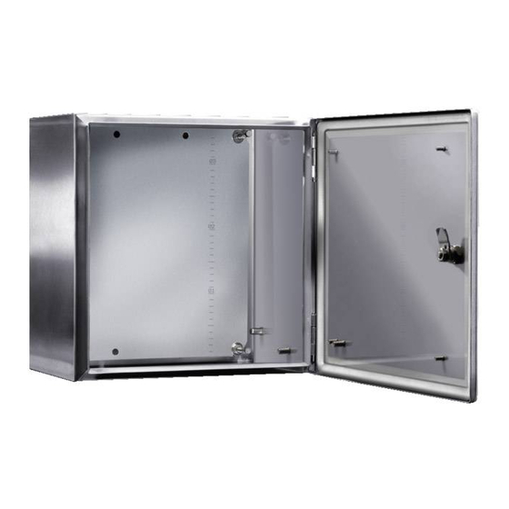
- Page 1 Leergehäuse/ Klemmengehäuse Empty Enclosure / Terminal Enclosure KEL 9401 - KEL 9416 KEL 9490 - KEL 9495 KE 9401 - KE 9416 KE 9490 - KE 9495 Montage- und Bedienungsanleitung Assembly and operating instructions...
-
Page 2: Table Of Contents
Zielgruppe: Audience: Erfahrene Elektrofachkräfte gemäß Betriebssicherheitverordnung Experienced electricians in accordance with the operational und unterwiesene Personen safety decree and instructed persons Inhalt: Table of Contents: 1. Verwendung ......3 1. -
Page 3: Verwendung
1. Verwendung 1. Use Die Leergehäuse/Klemmengehäuse aus Edelstahl sind zum The empty enclosures / terminal enclosures made of stainless Einbau von Ex-Bauteilen und Klemmen geeignet. steel are designed for installation of Ex components and termi- nals. 2. Zweck der Anleitung 2. -
Page 4: Technische Daten
5. Technische Daten 5. Technical data Kennzeichnung: Identification: Gasexplosionsgefährdete Bereiche Gas-explosion-endangered areas 0102 II 2 G Ex eb IIC 0102 II 2 G Ex eb IIC CE 0102 II 2 G Ex eb IIC T6, T5 CE 0102 II 2 G Ex eb IIC T6, T5 CE 0102 II 2 G Ex eb ia IIC T6, T5 CE 0102... -
Page 5: Installation
760 x 760 x 210 = 07 760 x 760 x 210 = 07 800 x 1000 x 300 = 08 800 x 1000 x 300 = 08 300 x 380 x 210 = 09 300 x 380 x 210 = 09 200 x 300 x 120 = 10... -
Page 6: Kabel Und Leitungseinführungen
7. Leitungseinführungen (KEL) 7. Cable and wire entries Es können Kabel- und Leitungseinführungen sowie Verschluss- Cable and wire entries as well as sealing plugs made of metal stopfen aus kälteschlagbeständigem Kunststoff oder aus Metall or cold impact resistant plastic can be used. All cable and wire eingesetzt werden. -
Page 7: Maximale Anzahl Der Kabel Und Leitungseinführungen
8. Max. Anzahl der Kabel- und Leitungseinführungen 8. Maximum number of cable and wire entries 8a) Gehäuse ohne Flanschplatten Die maximale Anzahl von Leitungseinführungen bei dem Gehäu- Die maximale Anzahl von Leitungseinführungen bei dem Gehäu- se KEL/KE 9401 beträgt / The maximum number of cable/wire se KEL/KE 9405 beträgt / The maximum number of cable/wire entries on the KEL/KE 9401 enclosure is as follows: entries on the KEL/KE 9405 enclosure is as follows:... - Page 8 Die maximale Anzahl von Leitungseinführungen bei dem Gehäu- Die maximale Anzahl von Leitungseinführungen bei dem Gehäu- se KEL/KE 9409 beträgt / The maximum number of cable/wire se KEL/KE 9413 beträgt / The maximum number of cable/wire entries on the KEL/KE 9409 enclosure is as follows: entries on the KEL/KE 9413 enclosure is as follows: Größe / Seite Größe / Seite...
- Page 9 8b) Gehäuse mit Flanschplatten Die maximale Anzahl von Leitungseinführungen bei dem Gehäu- Die maximale Anzahl von Leitungseinführungen bei dem Gehäu- se KEL/KE 9401 mit Flanschplatten beträgt / The maximum se KEL/KE 9405 mit Flanschplatten beträgt / The maximum number of cable/wire entries on the KEL/KE 9401 with enclo- number of cable/wire entries on the KEL/KE 9405 enclosure is sure is as follows: as follows:...
- Page 10 Die maximale Anzahl von Leitungseinführungen bei dem Gehäu- Die maximale Anzahl von Leitungseinführungen bei dem Gehäu- se KEL/KE 9411 mit Flanschplatten beträgt / The maximum se KEL/KE 9414 mit Flanschplatten beträgt / The maximum number of cable/wire entries on the KEL/KE 9411 enclosure is number of cable/wire entries on the KEL/KE 9414 enclosure is as follows: as follows:...
-
Page 11: Gehäusebefestigung
9. Gehäusebefestigung 9. Enclosure attachment Maßskizze Dimension sketch 9401 9402 9403 9404 9405 9406 9407 9408 9409 9410 9411 9412 9413 9414 9415 9416 9490 9491 9492 9493 9494 9495 1300 1100 1000 1200 1330 1130 Anzahl der Vorreiber/ 10. Schutzleiteranschluss / 10. - Page 12 Die Anschlusspunkte für Schutzleiter und Potentialausgleichs- The terminals for the protective earth and equipotential bonding leiter ermöglichen den Anschluss mindestens eines Leiters und conductor are designed to accept at least one conductor. The sind wie folgt querschnittsmäßig zu bemessen: cross-sections must be selected as follows: Querschnitt des Phasen- Mindestquerschnitt des zuge- Cross-section of the phase wire...
-
Page 13: Bestückung, Einbauten - Nichteigensichere Stromkreise
11. Bestückung, Einbauten – nichteigen- 11. Configuration and internal components sicherer Stromkreise – non-intrinsically safe circuits Zur Klemmenbestückung sind Ex-Reihenklemmen nach EN Use Ex terminal blocks that comply with EN 60079-7 Section 60079-7 Abschnitt 13 zu verwenden. Diese Ex-Bauteile sind Teil eines Ex-Betriebsmittels und dürfen These Ex components are part of an Ex apparatus, and as such als solche nur in Verbindung mit einem teilbescheinigten Ge- they may only be used together with a partially certified enclo-... -
Page 14: Bestückung, Einbauten - Eigensichere Stromkreise
13. Bestückung, Einbauten - 13. Configuration and internal components eigensicherer Stromkreise – intrinsically safe circuits Anschlussklemmen für eigensichere Stromkreise müssen von Terminals for intrinsically safe circuits must be separated from denen für nicht eigensichere Stromkreise getrennt werden. Die non-intrinsically safe circuits. You can achieve separation Trennung durch Abstand wird erzielt, durch ein Abstandsmaß... -
Page 15: Bestückung Der Klemmengehäuse Serie Ke 94Xx
14. Bestückung der Klemmengehäuse Serie KE 94xx. 14. Configuration of series KE 94xx terminal enclosures Maximale Anzahl der Leiter in Abhängigkeit von Querschnitt und Maximale Anzahl der Leiter in Abhängigkeit von Querschnitt und dem zulässigen Dauerstrom für Gehäusegröße KE 9401. dem zulässigen Dauerstrom für Gehäusegröße KE 9404. - Page 16 Maximale Anzahl der Leiter in Abhängigkeit von Querschnitt und Maximale Anzahl der Leiter in Abhängigkeit von Querschnitt und dem zulässigen Dauerstrom für Gehäusegröße KE 9407. dem zulässigen Dauerstrom für Gehäusegröße KE 9410. Maximum number of conductors depending on the cross-section Maximum number of conductors depending on the cross-section and the allowable constant current for enclosure size KE 9407.
- Page 17 Maximale Anzahl der Leiter in Abhängigkeit von Querschnitt und Maximale Anzahl der Leiter in Abhängigkeit von Querschnitt und dem zulässigen Dauerstrom für Gehäusegröße KE 9413. dem zulässigen Dauerstrom für Gehäusegröße KE 9416. Maximum number of conductors depending on the cross-section Maximum number of conductors depending on the cross-section and the allowable constant current for enclosure size KE 9413.
- Page 18 Die Berechnung der max. Klemmenbestückung und die Er- Rittal can calculate the maximum number of terminals and gene- stellung der zugehörigen Beiblätter für Sondergehäuseabmes- rate insert sheets for special sizes as part of prototype testing sungen im Rahmen der Baumusterprüfbescheinigung kann...
-
Page 19: Installation- Und Bestückungshinweise
15. Installations- und Bestückungshinweise 15. Installation and configuration information Nach EN 60079-0 und EN 60079-7 wird zur Einhaltung der The maximum number of conductors *) depending on the cross- Temperaturparameter die maximale Anzahl der Leiter *) in Ab- section and the allowable constant current is used as the basis hängigkeit von Querschnitts und zulässigem Dauerstromes for determining conformance to the temperature parameters as zugrunde gelegt. -
Page 20: Mindestabstände Für Leitungsführung
16. Mindestabstände für Leitungsführung 16. Minimum Cable Routing Spacing Um eine übersichtliche Leitungsführung und einen sicheren An- To ensure that cable routing is orderly and the conductors are schluß der Leitungen an die Reihenklemmen zu gewährleisten, securely fastened to the terminal blocks, sufficient spacing must ist zwischen der Gehäusewand und den Reihenklemmen bzw. -
Page 21: Inbetriebnahme
19. Zubehör und Ersatzteile 19. Accessories and spare parts ES DÜRFEN NUR ORGINAL ZUBEHÖR UND ONLY GENUINE ACCESSORIES AND SPARE ORGINAL ERSATZTEILE DER FIRMA RITTAL-WERK PARTS MADE BY RITTAL D-35745 HERBORN D-35745 HERBORN VERWENDET WERDEN. MAY BE USED 20. Entsorgung 20. Disposal Es sind die nationalen Abfallbeseitigungsvorschriften zu beachten. - Page 28 Power Distribution Climate Control IT Infrastructure Software & Services You can find the contact details of all Rittal companies throughout the world here. www.rittal.com/contact RITTAL GmbH & Co. KG Postfach 1662 · D-35726 Herborn Phone +49(0)2772 505-0 · Fax +49(0)2772 505-2319...
Need help?
Do you have a question about the KEL 9401 and is the answer not in the manual?
Questions and answers