Sign In
Upload
Download
Table of Contents
Contents
Add to my manuals
Delete from my manuals
Share
URL of this page:
HTML Link:
Bookmark this page
Add
Manual will be automatically added to "My Manuals"
Print this page
×
Bookmark added
×
Added to my manuals
Manuals
Brands
Frontier Manuals
Farm Equipment
DH1276
Operator's manual
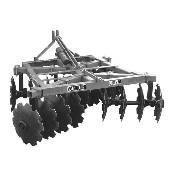
Frontier DH1276 Operator's Manual
Disc harrows
Hide thumbs
1
2
Table Of Contents
3
4
5
6
7
8
9
10
11
12
13
14
15
16
17
18
19
20
21
22
23
24
25
26
page
of
26
Go
/
26
Contents
Table of Contents
Troubleshooting
Bookmarks
Table of Contents
Introduction II
Table of Contents
Specifications / General Information
Safety Decals 2
Safety Rules 6
Dealer Instructions 7
Operation 8
Trouble Shooting 10
Owner Service 11
Parts Catalog 12
Optional Equipment 15
Bolt Size and Bolt Torque Chart 19
Warranty 20
Warranty for Parts 21
Notes 22
Advertisement
Quick Links
1
Introduction II
2
Specifications / General Information
3
Operation 8
4
Owner Service 11
5
Parts Catalog 12
Download this manual
DH12_TL15192_10/06
Table of
Contents
Previous
Page
Next
Page
1
2
3
4
5
Advertisement
Table of Contents
Need help?
Do you have a question about the DH1276 and is the answer not in the manual?
Ask a question
Questions and answers
Related Manuals for Frontier DH1276
Farm Equipment Frontier DH3499 Operating Manual
Offset disk harrows (24 pages)
Farm Equipment Frontier DH3409 Operating Manual
Offset disk harrows (24 pages)
Farm Equipment Frontier DH5410C Operator's Manual
Offset construction disks (50 pages)
Farm Equipment Frontier DH1380 Operator's Manual
Disk harrows (24 pages)
Farm Equipment Frontier DH1396 Series Operator's Manual
Disk harrows (24 pages)
Farm Equipment Frontier DH1376 Operator's Manual
Disk harrows (24 pages)
Farm Equipment Frontier DH1280 Operator's Manual
Disc harrows (26 pages)
Farm Equipment Frontier DH1296 Operator's Manual
Disc harrows (26 pages)
Farm Equipment Frontier DC1000 Operator's Manual
Disc/mower caddy (32 pages)
Farm Equipment Frontier RB1172 Operator's Manual
Rear blades (24 pages)
Farm Equipment Frontier AD11 Operator And Parts Manual
Bucket loader attachments (86 pages)
Farm Equipment Frontier RT 1142 Operator's Manual
Rotary tillers (74 pages)
Farm Equipment Frontier WR2214 Operator's Manual
High-capacity wheel rake (108 pages)
Farm Equipment Frontier WR0008 Operator's Manual
Carted wheel rake (6 pages)
Farm Equipment Frontier BB2272 Operator's Manual
Box blades (16 pages)
Farm Equipment Frontier BB5060 Operator's Manual
Box blades (20 pages)
This manual is also suitable for:
Dh1280
Dh1296
Dh1048
Dh1066
Table of Contents
Print
Rename the bookmark
Delete bookmark?
Delete from my manuals?
Login
Sign In
OR
Sign in with Facebook
Sign in with Google
Upload manual
Upload from disk
Upload from URL


Need help?
Do you have a question about the DH1276 and is the answer not in the manual?
Questions and answers