Table of Contents
Advertisement
Quick Links
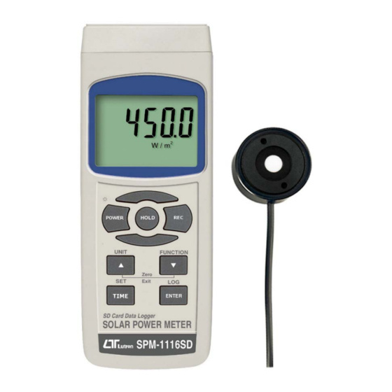
SD card real time Data Recorder
SOLAR POWER METER
Model : SPM-1116SD
OPERATION MANUAL
Your purchase of this
SOLAR POWER METER
with SD CARD DATA
RECORDER
marks
step forward for you
into
the
field
precision measurement.
A l t h o u g h
DATALOGGER
complex
and
instrument, its durable
structure
will
many years of use if
p r o p e r
o p e r a t i n g
t e c h n i q u e s
developed. Please read
t h e
f o l l o w i n g
instructions
carefully
and always keep this
manual
within
reach.
a
of
t h i s
is
a
delicate
allow
a r e
easy
Advertisement
Table of Contents

Related Manuals for Lutron Electronics SPM-1116SD


Summary of Contents for Lutron Electronics SPM-1116SD
- Page 1 SD card real time Data Recorder SOLAR POWER METER Model : SPM-1116SD Your purchase of this SOLAR POWER METER with SD CARD DATA RECORDER marks step forward for you into field precision measurement. A l t h o u g h...
- Page 2 TABLE OF CONTENTS 1. FEATURES................1 2. SPECIFICATIONS..............2 3. FRONT PANEL DESCRIPTION............. 5 3-1 Display................5 3-2 Power Button..............5 3-3 Hold Button ( Backlight Button )........... 5 3-4 REC Button ..............3-5 UNIT Button ( Button, Zero/Exit )........▲...
- Page 3 1. FEATURES * 3 functions : Solar power, Power integration, Transmission. * Wide spectral range. * Excellent long term stability. * Select either W/m^2 or Btu / (ft^2xh) power units. * Cosine corrected. * Application : Meteorology agriculture solar radiation measurement solar power research physics and optical laboratories solar transmission measurement identify high performance windows...
-
Page 4: Specifications
* SD card capacity : 1 GB to 16 GB. * LCD with green light backlight, easy reading. * Can default auto power off or manual power off. * Data hold, record max. and min. reading. * Microcomputer circuit, high accuracy. * Power by UM3/AA ( 1.5 V ) x 6 batteries or DC 9V adapter. - Page 5 Display LCD size : 52 mm x 38 mm LCD with green backlight ( ON/OFF ). Zero Adj. By push button. Datalogger Auto 1 second to 3600 seconds Sampling Time @ Sampling time can set to 1 second, Setting range but memory data may loss.
- Page 6 Power Supply Alkaline or heavy duty DC 1.5 V battery ( UM3, AA ) x 6 PCs, or equivalent. DC 9V adapter input. ( AC/DC power adapter is optional ). Power Current Normal operation ( w/o SD card save data and LCD Backlight is OFF) : Approx.
-
Page 7: Front Panel Description
3. FRONT PANEL DESCRIPTION 3-1 Display 3-2 Power Button ( Backlight Button ) 3-3 Hold Button 3-4 REC Button 3-5 UNIT Button ( Button, Zero/Exit ) ▲ 3-6 SET Button ( TIME Button ) 3-7 FUNCTION Button ( Button, Zero/Exit ) ▼... -
Page 8: Measuring Procedure
4. MEASURING PROCEDURE 4-1 Power on/off 1) Power on the meter by pressing the " Power button " ( 3-2, Fig. 1 ) > 1.5 SECONDS continuously. After already power on the meter, pressing the 2)" Power button " > 1.5 SECONDS continuously will turn off the meter. - Page 9 Pressing the " FUNCTION Button " ( 3-7, Fig. 1 ) > 1.5 SECONDS ( not release the button ), the Display will show the text " P, tr, P-I " in sequence : Display Function Text Solar power Transmission Solar power integration 2)Until the Display show the desired Function, just release the "...
- Page 10 4-5 Transmission measurement 1)Install the " Probe Plug " ( 3-18, Fig. 1 ) into the " Probe Input Socket " ( 3-9, Fig. 1 ). 2)a. Power on the meter. Function should select to " Transmission " ( tr ), refer to chapter 4-3.
- Page 11 3)There are two " Integration time " modes : Mode 1 : Integration from the " Zero second " Mode 2 : Integration from the " Existing time " Mode 1 : Integration from the " Zero second " a. Press the " TIME Button " ( 3-6, Fig. 1 ) once, the left lower Display will show "...
- Page 12 4-7 Data Hold During the measurement, press the " Hold Button " ( 3-3, Fig. 1 ) once will hold the measured value & the LCD will display a " HOLD " symbol. Press the " Hold Button " once again will release the data hold function.
-
Page 13: Data Logger
5. DATALOGGER 5-1 Preparation before execute datalogger function a. Insert the SD card Prepare a " SD memory card " ( 1 G to 16 G, optional ), insert the SD card into the " SD card socket " ( 3-10, Fig. 1). The front panel of the SD card should face against the the down case. - Page 14 5-2 Auto Datalogger ( Set sampling time 1 second ) ≧ a. Start the datalogger Press the " LOG Button ( 3-8, Fig. 1 ) > 1.5 SECONDS continuously, the lower LCD will show the text of " Log " then "...
- Page 15 5-3 Manual Datalogger ( Set sampling time = 0 second ) a. Set sampling time is to 0 second Press the " LOG Button ( 3-8, Fig. 1 ) > 3 second , the lower LCD will show the " Position no. " , then press the "...
- Page 16 5-5 SD Card Data structure 1)When the first time, the SD card is used into the meter, the SD card will generate a folder : SPM01 2)If the first time to execute the Datalogger, under the route SPM01\, will generate a new file name SPM01001.XLS.
- Page 17 6. Saving data from the SD card to the computer ( EXCEL software ) 1)After execute the Data Logger function, take away the SD card out from the " SD card socket " ( 3-10, Fig. 1 ). 2)Plug in the SD card into the Computer's SD card slot ( if your computer build in this installation ) or insert the SD card into the "...
-
Page 18: Advanced Setting
EXCEL graphic screen ( for example ) 7. ADVANCED SETTING Under do not execute the Datalogger function, press the " SET Button " ( 3-6, Fig. 1 ) continuously at least two seconds will enter the " Advanced Setting " mode. then press the "... -
Page 19: Set Clock Time ( Year/Month/Date, Hour/Minute/ Second )
Remark : During execute the " Advanced Setting " function, if press " SET Button " ( 3-6, Fig. 1 ) > 1.5 SECONDS will exit the " Advanced Setting " function, the LCD will return to normal screen. 7-1 Set clock time ( Year/Month/Date, Hour/Minute/ Second ) When the lower display show "... - Page 20 7-2 Set sampling time ( Seconds ) When the lower display show " SP-t " 1)Use the " Button " ( 3-5, Fig. 1 ) or " Button " ( ▲ ▼ 3-7, Fig. 1 ) to adjust the value ( 0, 1, 2, 5, 10, 30,60, 120, 300, 600, 1800,3600 seconds ).
- Page 21 yES - Meter's beep sound will be ON with default. no - Meter's beep sound will be OFF with default. is power ON. 2)After select the upper text to " yES " or " no ", press the " ENTER Button " ( 3-8, Fig. 1 ) will save the setting function with default.
-
Page 22: Power Supply From Dc Adapter
yES - Intend to format the SD memory card no - Not execute the SD memory card format 2)If select the upper to " yES ", press the " Enter Button " ( 3-8, Fig. 1 ) once again, the Display will show text "... -
Page 23: System Reset
10. SYSTEM RESET If the meter happen the troubles such as : CPU system is hold ( for example, the key button can not be operated... ). Then make the system RESET will fix the problem. The system RESET procedures will be either following method : During the power on, use a pin to press the "... - Page 24 Meter (9W 'D" Connector) Center Pin......Pin 4 (3.5 mm jack plug) Ground/shield.......Pin 2 2.2 K resistor Pin 5 The 16 digits data stream will be displayed in the following format : D15 D14 D13 D12 D11 D10 D9 D8 D7 D6 D5 D4 D3 D2 D1 D0 Each digit indicates the following status : End Word D1 &...
- Page 25 RS232 FORMAT : 9600, N, 8, 1 Baud rate 9600 9600 Parity No parity Data bit no. 8 Data bits Stop bit 1 Stop bit 12. PATENT The meter ( SD card structure ) already get patent or patent pending in following countries : Germany Nr.
Need help?
Do you have a question about the SPM-1116SD and is the answer not in the manual?
Questions and answers