Deye SUN-3.6K-SG03LP1-EU User Manual
Hybrid inverter
Hide thumbs
Also See for SUN-3.6K-SG03LP1-EU:
- User manual (56 pages) ,
- User manual (51 pages) ,
- User manual (51 pages)
Table of Contents

Related Manuals for Deye SUN-3.6K-SG03LP1-EU


Summary of Contents for Deye SUN-3.6K-SG03LP1-EU
- Page 1 Hybrid Inverter SUN-3.6K-SG03LP1-EU SUN-5K-SG03LP1-EU User Manual Add: No.26-30, South Yongjiang Road, Beilun, 315806, Ningbo, China Tel: +86 (0) 574 8622 8957 Fax: +86 (0) 574 8622 8852 E-mail: wutz@deye.com.cn Web: www.deyeinverter.com...
-
Page 2: Table Of Contents
Contents Contents Contents ……………………………………………… 5.8 Grid Setup Menu ……………………………………………… 5.9 Generator Port Use Setup Menu 2.1 Product Overview 5.10 Advanced Function Setup Menu 2.2 Product Features 5.11 Device Info Setup Menu 2.3 Basic System Architecture …………………………………………………………………… …………………………………………………………… ………………………………… 3.1 Parts list …………………………………………………... -
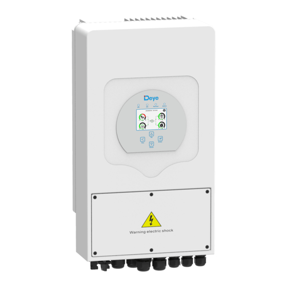
Page 3: Product Overview
1. Safety Introductions 2.1 Product Overview ・This chapter contains important safety and operating instructions. Read and keep this manual for future reference. ・Before using the inverter, please read the instructions and warning signs of the battery and corresponding sections in the instruction manual. ・Do not disassemble the inverter. -
Page 4: Product Features
2.2 Product Features AC cable DC cable WiFI ・ -220V Single phase Pure sine wave inverter. GPRS Cloud services phone ・ - Self-consumption and feed-in to the grid. ・ - Auto restart while AC is recovering. ・ - Programmable supply priority for battery or grid. Wind Solar Backup Load... -
Page 5: Mounting Instructions
・ The ambient temperature should be between -25~60℃ to ensure optimal operation. Current transformer (Optional) ・ Be sure to keep other objects and surfaces as shown in the diagram to guarantee Battery sensor sufficient heat dissipation and have enough space for removing wires. L-type Hexagon wrench ≥500mm Wall mounting bracket... -
Page 6: Battery Connection
All wiring must be performed by a professional person. Connecting the battery with a suitable cable is important for safe and efficient operation of the system. To reduce the risk of injury, refer to Chart 3-2 for recommended cables. Please follow below steps to implement battery connection: 1. -
Page 7: Ac Input/Output Connection
3.3.2 Battery temperature connection 3.4 AC Input/Output Connection ・ Before connecting to AC input power source,please install a separate AC breaker between inverter and AC input power source.This will ensure the inverter can be securely disconnected during maintenance and fully protected from over current of AC input.The recommended of AC breaker is 25A for 3.6kw and 32A for 5KW. -
Page 8: Pv Connection
Be sure that AC power source is disconnected before attempting to wire it to It is requested to use PV junction box with surge protection. Otherwise,it the unit. will cause damage on inverter when lightning occurs on PV modules. 3. Then,insert AC output wires according to polarities indicated on the terminal block and tighten terminal. -
Page 9: Ct Connection
3.9 Wiring System for Inverter 3.6 CT Connection Inverter White wire Black wire Grid 3.7 Earth Connection(mandatory) Ground cable shall be connected to ground plate on grid side this prevents electric shock. if the original protective conductor fails. 3.8 WIFI Connection For the configuration of Wi-Fi Plug,please refer to illustrations of the Wi-Fi Plug. -
Page 10: Single Phase Parallel Connection Diagram
3.10 Single phase parallel connection diagram 3.11Three phase Parallel Inverter Inverter No.3 (slave) DSM 485 DSM CAN DRMs Ground Parallel A Parallel B Inverter Inverter No.2 (slave) Inverter No.1 (master) Battery pack Grid Master inverter Slave Inverter Slave Inverter Advanced Function Advanced Function Advanced Function Parallel... -
Page 11: Power On/Off
4. OPERATION 5. LCD Display Icons 4.1 Power ON/OFF 5.1 Main Screen Once the unit has been properly installed and the batteries are connected well,simply press The LCD is touchscreen,below screen shows the overall information of the inverter. On/Off button(located on the left side of the case) to turn on the unit.When system without battery connected,but connect with either PV or grid,and ON/OFF button is switched off, 05/28/2019 15:34:40 LCD will still light up(Display will show OFF),In this condition,when switch on ON/OFF... -
Page 12: Main Screen
5.1.1 LCD operation flow chart 5.2 Solar Power Curve Solar This is Solar Panel detail page. Solar Panel Generation. Power: 1560W Today=8.0 KWH Solar Page Solar Graph Voltage,Current,Power for each MPPT. PV1-V: 286V PV2-V: 45V Total =12.00 KWH PV1-|: 5.5A PV2-|: 0.0A Solar Panel energy for Day and Total. -
Page 13: Curve Page-Solar & Load & Grid
Li-BMS 5.4 System Setup Menu Mean Voltage:50.34V Charging Voltage :53.2V Batt Total Current:55.00A Discharging Voltage :47.0V System Setup Data Mean Temp :23.5C Charging current :50A This is System Setup page. Stand-by Total SOC :38% Discharging current :25A Dump Energy:57Ah SOC: 36% Details System Work Mode Data... -
Page 14: System Work Mode Setup Menu
Battery Setting Lithium Mode--This is BMS protocol.Please reference the document(Approved Battery-Deye). Lithium Mode Time of use Shutdown 10%--It indicates the inverter will shutdown if Batt the SOC below this value. -
Page 15: Grid Setup Menu
5.8 Grid Setup Menu 5.9 Generator Port Use Setup Menu Grid Setting GEN PORT USE Generator Input:use Generator Please select the correct Grid Mode in your local area. If Grid Mode General Standard Mode you are not sure, please choose General Standard. SmartLoad Output: if the SOC is up than Generator Input Gen connect to Grid input... -
Page 16: Device Info Setup Menu
PassWord Factory restart: 9999 X--X--X--X Lock out all changes:7777 AC cable DC cable Wind Backup Load On-Grid Home Load CANCEL Grid 5.11 Device Info Setup Menu Battery Li-BMS Li-BMS Device Info. This page show Inverter ID, Inverter version Inverter ID: 1601012001 Charge Charge Volt... - Page 17 Error code Description Solutions Inverter work mode changed Working mode change 1. wait for a mintue and check; On-Grid+AC couple AC cable DC cable 2. Seek help from us, if can't go back to normal state. AC side over curent fault 1.
- Page 18 PV Input Voltage (V) 370V(100V~500V) to Ningbo Deye Inverter Technology Co., Ltd. Factory warranty does not include damage due to the following reasons: MPPT Range (V) 125~425V...
- Page 19 Power Factor 0.8 leading to 0.8 lagging Output Frequency and Voltage 50/60Hz; 220/230/240Vac(single phase) Grid type Single Phase Current harmonic distortion THD<3%(Linear load) <1.5% Max. Efficiency 97.60% Euro Efficiency 96.50% MPPT Efficiency 99.90% PV Input Lightning Protection Integrated Anti-islanding Protection Integrated Integrated PV String Input Reverse Polarity Protection...
Need help?
Do you have a question about the SUN-3.6K-SG03LP1-EU and is the answer not in the manual?
Questions and answers