
Related Manuals for Dru Maestro 75 Tunnel RCH


Summary of Contents for Dru Maestro 75 Tunnel RCH
- Page 1 Installation manual Maestro 75 Tunnel RCH Maestro 75 Tall Tunnel RCH G20/G25/G25.3 (Natural gas), G30 (Butane) and G31 (Propane) English Store this document in a safe place DRU-938433-EN-US-0720-2 959.113.03.EN...
-
Page 2: Table Of Contents
I nst allat io n m anual Content 1. Step-by-step installation plan 2. Introduction 3. CE declaration 4. Technical data 5. SAFETY 5.1 General 5.2 Regulations 5.3 Safety instructions 6. Preparation 6.1 Unpacking 6.2 Type of gas 6.2.1 Gas type conversion 6.3 Gas connection 6.3.1 Gas hose for gas connection 6.4 Electric connection... - Page 3 7.5 Placing the control hatch 8 Toestel 8.1 Glass panes 8.1.1.1 Opening the glass pane 8.1.1.2 Removing the glass pane (Maestro 75 Tunnel RCH) 8.1.2 Removing the glass pane (Maestro 75 Tall Tunnel RCH) 8.1.2 Placing the glass pane 8.2 Setting the appliance 8.2.1 Restrictor slide...
-
Page 4: Step-By-Step Installation Plan
I nst allat io n m anual 1. Step-by-step installation plan The major steps of the installation are described below, Perform these steps and tick them once they have been performed correctly. Carefully read the installation manual before installing the appliance. Check that the correct type of appliance has been delivered (see table 4-1). -
Page 5: Introduction
Fully and carefully read and use this installation manual, before installing the appliance. When using the DRU Powervent system or DRU CM system , the accompanying installation manual should also be read completely and carefully, before ®... -
Page 6: Technical Data
* This appliance is suitable for G25.3 with the composition according NTA 8837. ** System efficiency. *** To be used by means of home automation. **** Adjusting screw. *****Categories C12 and C32 only in combination with DRU PV-1 100/60 (PowerVent®). -
Page 7: Safety
- Only use the flue gas discharge / combustion air supply system (concentric system) supplied by DRU. When installing a free-standing appliance: place the appliance at the indicated minimum distance from the back wall, as indicated further down in the text. -
Page 8: Preparation
Check whether the appliance is suitable for the type of gas and the gas pressure used at the location. 6.2.1 Gas type conversion In order to convert this appliance to a different type of gas, please contact DRU's service department and ask for the possibilities. The conversion should be performed by a recognised gas installer. -
Page 9: Gas Hose For Gas Connection
I nst allat io n m anual 6.3.1 Gas hose for gas connection In many cases, an EN14800-compliant gas hose for a gas connection can be ordered together with the appliance. The gas hose is mounted to the appliance and has been checked for leak-tightness. This gas hose is available in different lengths. Take the following into account when installing the gas connection and the appliance (see fig. -
Page 10: Components Appliance Control
I nst allat io n m anual 6.5 Components appliance control This section states the components that are used to control the appliance (see fig. 6-2). G(in) Legend: A = Gas control; controls the gas to the burners B = Receiver; communicates with the transmitter C = Processor (ESYS);... -
Page 11: Installatie
I nst allat io n m anual 7 Installatie 7.1 Placing the appliance Separate sub-sections describe different ways of placing the appliance. The general description below for placing the appliance applies to all these sub-sections: Place the appliance where it will be installed and observe the following: - The construction dimensions of the appliance (see fig. - Page 12 I nst allat io n m anual 38C-2549/1 Maestro 75 Tunnel RCH...
- Page 13 I nst allat io n m anual 38C-2726/0 Maestro 75 Tall Tunnel RCH...
-
Page 14: Additional Installation Options Of The Construction Frame
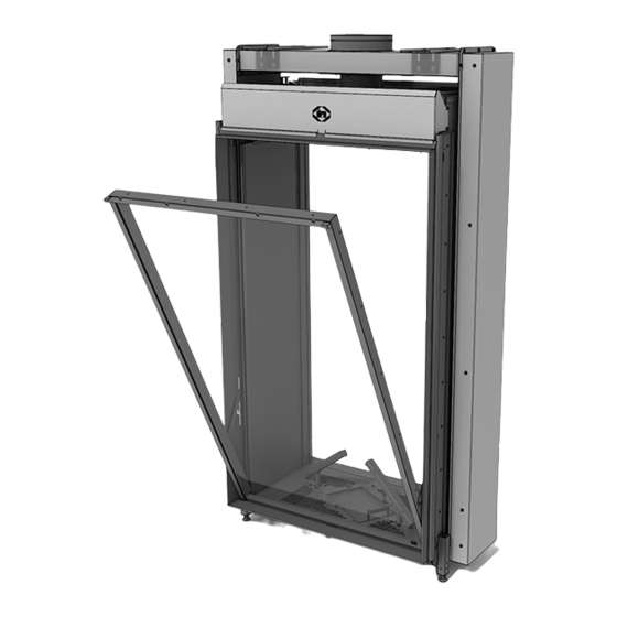
I nst allat io n m anual 7.2 Additional installation options of the construction frame The construction frame of this appliance can be adjusted from the “4S version” to the “3S version” (see fig. 7-3). The 3S version allows you to fit the glass pane against the floor or platform. When using the 3S construction frame, the platform or floor in front of and next to the appliance has to be made with inflammable material (see section 7.4) No other information can be provided, nor can responsibility be accepted for the way in which floor covering or other... -
Page 15: Concentric System
7.3 Concentric system 7.3.1 General The appliance is connected to a flue gas discharge / combustion air supply system delivered by DRU, hereafter referred to as the concentric system. DRU has different concentric systems in its range. In the case of a concentric system, the inner tube is used as flue gas discharge. The combustion air is supplied by the outer tube. - Page 16 Build the system up from (the flue spigot of) the appliance. Connect the concentric pipe pieces and, if necessary, the bend(s). Apply a clip binding with silicon sealing ring on each connection (does not apply to DRU LAS ES-E 200/150/100, here the sealing ring is inside the tube).
-
Page 17: Roof Terminal (C31)
I nst allat io n m anual 7.3.2 Roof terminal (C31) The roof terminal can end in a sloping and a flat roof. The roof terminal can be supplied with an adhesive plate for a flat roof or with a universally adjustable tile for a sloping roof. - Page 18 3 bends 4 bends 5 bends Situation is not permissible. There are many more possibilities in combination with the DRU PowerVent system (DRU PV-I 100/60) (see PowerVent installation manual). Table 7-4: Conditions for setting the appliance when using a roof terminal G20/G25/G25.3/G30/G31...
- Page 19 I nst allat io n m anual...
-
Page 20: Wall Terminal (C11)
I nst allat io n m anual 7.3.3 Wall terminal (C11) When using a wall terminal (C11), the following applies: The construction of the chosen system has to be allowed. Check that the vertical pipe length falls between the minimum and maximum lengths (see table 7-5). Check that the horizontal pipe length (wall terminal excluded) falls within the minimum and maximum length (see table 7-5). - Page 21 I nst allat io n m anual Tabel 7-5b Tabel 7-5c 1x90° 0 - 3m 1x90° 38C-744W 38C-744ZT Setting Maestro 75 Tunnel Apply Setting Maestro 75 Tunnel Apply Air inlet guide Air inlet guide Restrictor slide Restrictor slide - Only use 200/130 mm concentric system, including the - Only use 200/130 mm concentric system, including the 200/130 mm wall terminal.
- Page 22 Ins tal lati ehandleiding 0 - 8m 0 - 0.5m 1x90° 1x90° 38C-744ZF 38C-744ZZG Setting Maestro 75 Tall Tunnel Apply Setting Maestro 75 Tall Tunnel Apply Air inlet guide Air inlet guide Restrictor slide Restrictor slide -Install a connecting piece reducing the concentric system - Only use 200/130 mm concentric system, including the to 150/100 mm directly onto the appliance.
-
Page 23: Connection To An Existing Chimney
The appliance can be connected to an existing chimney (C91). A 100 mm diameter flexible SS pipe is placed in the chimney for discharging flue gases. The surrounding space is used as combustion air supply. Use the DRU spacer here. - Page 24 (prolonged application of painter's tape may cause damage). You should preferably apply the ventilation holes (outgoing) on both sides of the chimney breast. Use the DRU ventilation elements.
- Page 25 I nst allat io n m anual ≥1080 (*1) ≥15 ≤100 ≥ 402 V-Out ≥ 200cm² ≥ 420 1341** 2 mm ≥110 2 mm ≥410* ≥150 V-In ≥ 80cm² (LED: 2X ≥ 80cm²) 38C-2696 ≥150 7-13 * Taking into account the control hatch, placed as indicated. ** Maestro 75 Tall Tunnel RCH With LED appliances, an additional ventilation hole (V-in) must be installed.
-
Page 26: Placing The Control Hatch
7.5 Placing the control hatch A number of components are placed in the control hatch, such as data plate, gas control and, if applicable, components belonging to the DRU Powervent System ® The control hatch was designed in such a way, that all components as well as adjustment, measurement and regulating provisions are within optimum reach and the components work optimally. - Page 27 I nst allat io n m anual 180° 180° >15mm 180° 38c-2511-1 7-15...
-
Page 28: Toestel
The glass pane is now in the ‘parked position’. (see fig. 8-1 step 4). 8.1.1.2 Removing the glass pane (Maestro 75 Tunnel RCH) Remove the glass pane by lifting it from the 'parked position'. - Page 29 I nst allat io n m anual 180° 38C-2707 38C-2708...
-
Page 30: Placing The Glass Pane
I nst allat io n m anual 38C-2711 8.1.2 Placing the glass pane The glass pane is fitted by using the above procedure, in reverse order (see fig. 8-1, 8-2 and 8-3): Avoid/remove fingerprints on the glass pane, as they will burn into the glass. Lubricate rotating parts and glide planes with a heat-resistant lubricant, such as copper grease. -
Page 31: Setting The Appliance
I nst allat io n m anual 8.2 Setting the appliance The appliance has to be set in such a way that it works correctly in combination with the concentric system. For that purpose, a restrictor slide is possibly adjusted or removed and an air inlet guide is placed. The conditions for application with wall terminal and roof terminal are stated in tables 7-3 to 7-5. -
Page 32: Air Inlet Guide
I nst allat io n m anual 5.13.2 Air inlet guide The air inlet guide assembly consists of an air inlet guide (L1); it is located under the vermiculite plate on the left and right side, the second air inlet guide (L2) is supplied separately. When placing the air inlet guide (L2), proceed as follows (see fig. -
Page 33: Placing The Wood Set
I nst allat io n m anual 8.3 Placing the wood set The appliance is supplied with a wood set. The figures do not always show the correct colours. Observe the instructions below to prevent unsafe situations: - Only ever use the supplied wood set. - Place the wood set exactly as described. - Page 34 I nst allat io n m anual 38P-0759-0 38p-0022 38P-0608 8-10 8-11 38P-0609 38P-0028 /1 8-12 8-13...
- Page 35 I nst allat io n m anual 8-14 For appliances without LEDs, use all chips in the wood set. Fill the vermiculite plates with chips, spread the chips evenly, keep the sections marked in red free of chips (see fig. 8-18). For appliances with LEDs, use the glow rocks, coals and a portion of the chips.
- Page 36 I nst allat io n m anual 38P-0862 8-15...
- Page 37 I nst allat io n m anual 38P-0859 8-16 38P-0860 8-17...
- Page 38 I nst allat io n m anual 38P-0763 8-18 38P-0855 8-19...
- Page 39 I nst allat io n m anual 38P-0857 8-20...
- Page 40 I nst allat io n m anual 38P-0854 8-21 38P-0856 8-22...
- Page 41 38P-0858 8-23 38P-0861 8-24...
- Page 42 I nst allat io n m anual...
-
Page 43: Control/Operation
I nst allat io n m anual 9. Control/operation The appliance is supplied with a wireless black remote control for the user (see fig. 9-1 (B)). As an option, an orange remote control can be supplied for the installer (see fig. 9-1 (O)). Flame height, ignition and switching off are controlled by the black remote control controlling the receiver. -
Page 44: Principle Of Ignition Cycle
It is possible to operate one or more lamps (in case of several lamps, a maximum of 0,5A/250VAC/30VDC) via the remote control of the appliance. You could think of the lamps of Dru's lux elements. For this, you can use switch contact B on the receiver (see fig. -
Page 45: Connection Extra Power Supply (Max. 80W, 230Vac)
I nst allat io n m anual 9.3 Connection extra power supply (max. 80W, 230VAC) (if applicable) This connection is ideal for possible lighting or a ventilation system in the chimney breast and can be operated by means of the remote control (see Fig. 9-2 (C)). The power supply of this connection is identical to the mains voltage and it can be subjected to a maximum load of 80 Watts. -
Page 46: Wired
I nst allat io n m anual 9.5.1 Wired Wired connection of the home automation system to the receiver takes place via a 0-3VDC direct current (see fig. 9-2 (D)). A higher voltage than 3V will damage the receiver and is therefore not permitted. In case of home automation systems with an output voltage of 0-10V, you should switch the voltage back to 0-3VDC. -
Page 47: Wireless
9.5.2.2 Control via application Also when operating the appliance via a tablet provided with the DRU Control App (iOS or Android), you will need a communication module. This module can be ordered from DRU. In order to control the application via the DRU Control App, proceed as follows: Use the remote control to test whether the location where the communication module will be placed is within the reach of the receiver. -
Page 48: Final Inspection
I nst allat io n m anual 10. Final inspection For a good and safe operation of the appliance, the following checks must be performed prior to commissioning. 10.1 Gas tightness All connections must be gas tight. Check the connections for gas tightness. The gas control can be subjected to a maximum pressure of 50 mbar. -
Page 49: Procedure For Igniting The Main Burner
I nst allat io n m anual If the main burner DOES continue to burn: 11. Clean the glass pane before using it for the first time, as described in the user manual. Then mount the glass pane as described in chapter 8. 12. -
Page 50: Delivery
I nst allat io n m anual 11. Delivery Familiarise the user with the appliance. Provide the user with instructions on putting it into operation, the safety measures, the operation of the remote control and annual maintenance (see the User Manual). - Tell the user to close the gas tap immediately and contact the installer in case of malfunctions/poor operation. -
Page 51: Maintenance
I nst allat io n m anual 12. Maintenance Once per year, the appliance must be checked, cleaned and, if necessary, repaired by a competent installer in the field of gas heating and electricity. At least check that the appliance is working properly and safely. - Always close the gas tap during maintenance work. -
Page 52: Appendix 1: Malfunctions
I nst allat io n m anual Appendix 1: Malfunctions Malfunctions Error code Problem Possible cause Remedy Communication loss between Communication cable does Make sure the connectors receiver and burner device not make contact of the communication cable make proper contact Communication cable defective Replace communication cable Receiver overheated... - Page 53 I nst allat io n m anual Malfunctions Error code Problem Possible cause Remedy ESYS is not released ESYS is in hard-lock Wait half hour until ESYS resets itself F13/F14 (no ionisation). Flame Loss when only Ionisation pin short-circuited Remove chips, vermiculite or glow the main burner (F13) is on or material lying against the both burners (F14) are on...
- Page 55 I nst allat io n m anual...
- Page 56 I nst allat io n m anual DRU Verwarming B.V. The Netherlands Postbus 1021, NL-6920 BA Duiven Ratio 8, NL-6921 RW Duiven...
Need help?
Do you have a question about the Maestro 75 Tunnel RCH and is the answer not in the manual?
Questions and answers