Dru Maestro 75 RCH Installation Manual
Hide thumbs
Also See for Maestro 75 RCH:
- Installation manual (56 pages) ,
- Instruction manual (56 pages) ,
- Installation manual (56 pages)

Related Manuals for Dru Maestro 75 RCH


Summary of Contents for Dru Maestro 75 RCH
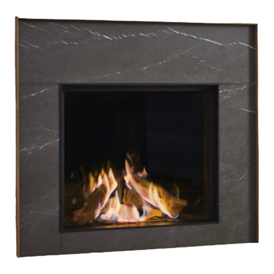
- Page 1 Maestro 75 RCH G20/G25/G25.3 (Natural gas) G31 (Propane) Installation manual Store this document in a safe place...
-
Page 2: Table Of Contents
I N S T A L LA T I O N M A N U A L Contents 1. Introduction 2. CE declaration 3. SAFETY 3.1 General 3.2 Regulations 3.3 Precautions / safety instructions at installation 3.4 Principle of ignition cycle 4. -
Page 3: Introduction
The figures are at the back of this installation manual, in the appendix. Fully and carefully read and use this installation manual, before installing the appliance. When using the DRU Powervent system® or DRU CM system®, the accompanying installation manual should also be read completely and carefully, before installation work is started. -
Page 4: Safety
This has to do with the temperature development in the chimney breast. Ø Only use the flue gas discharge / combustion air supply system supplied by DRU. Ø When installing a free-standing appliance: place the appliance away from the back wall by the minimum distance stated further down in the text. -
Page 5: Principle Of Ignition Cycle
IN S T A LLA TION M A NU A L 3.4 Principle of ignition cycle Below you will find a brief description of how this appliance is ignited. The receiver in the appliance will get a signal from the remote control to start the ignition process. The receiver will get the signal to start the ignition process. -
Page 6: Installation
It is possible to operate one or more lamps (in case of several lamps, a maximum of 8A/250VAC/30VDC) via the remote control of the appliance. You could think of the lamps of Dru's lux elements. For this, you can use switch contact B on the receiver (see appendix 3, fig 36). -
Page 7: Placing A Built-In Appliance
(if applicable) Not all built in DRU appliances are supplied with a control hatch. Built in appliances must be installed with the DRU control hatch. This is necessary to ensure a durable, safe and !Caution proper operation. The DRU control hatch can be ordered separately. Exceptions are: Appliances with supplied DRU guard cabinet. -
Page 8: Placing The Control Hatch
!Tip You should preferably apply the ventilation holes (outgoing) on both sides of the chimney breast. Use the DRU ventilation elements. Check the following issues, before the chimney breast is fully closed: •... - Page 9 IN S T A LLA TION M A NU A L Ø Attach the bracket with gas control to the inner frame (A). Proceed as follows: • Unwind the cables. This will, amongst other things, prevent a poor operation of the ignition. •...
-
Page 10: Concentric System
5.8 Concentric system 5.8.1 General The appliance is connected to a flue gas discharge / combustion air supply system delivered by DRU, hereafter referred to as the concentric system. The diameter for this connection is indicated in appendix 2, table 2. The passage to the outside can be created with a wall terminal (C11) or a roof terminal (C31). -
Page 11: Connection To An Existing Chimney (C91)
The following requirements apply when connecting to an existing chimney: • Only allowed when used in combination with the special DRU chimney set. The installation regulation is parat of the delivery. •... -
Page 12: Additional Instructions
I N S T A L LA T I O N M A N U A L 5.10 Additional instructions !Tip Extension legs are available for this appliance. Ø Attach the appliance to the wall using wall brackets (B) (see appendix 3, fig. 1). 5.10.1 Convection box For this appliance, it is possible to order an optional convection box. -
Page 13: Glass Pane
IN S T A LLA TION M A NU A L 5.12 Glass pane The glass pane is mounted in a steel frame. Only in case of a crack or break, it will be necessary to replace the glass pane in the steel frame. When the glass pane is referred to in this document, this will include the steel frame. !Caution •... -
Page 14: Setting The Appliance
I N S T A L LA T I O N M A N U A L 5.13 Setting the appliance The appliance has to be set in such a way that it works correctly in combination with the concentric system. For that purpose, a restrictor slide is placed and/or the air inlet guide is removed. -
Page 15: Placing The Wood Set
IN S T A LLA TION M A NU A L 5.14 Placing the wood set The appliance is supplied with a wood set. The figures do not always show the correct colours. !Caution Observe the instructions below to prevent unsafe situations: !Caution •... -
Page 16: Control
IN S TA LLA TION M A N U AL 6. Control The appliance is supplied with a wireless black remote control for the user (see appendix 3, fig. 35 (B)). As an option, an orange remote control can be supplied for the installer (see appendix 3, fig. 35 (O). Controlling the flame height, igniting and switching off take place through the black remote control controlling the receiver. - Page 17 6.2.2.2 Control via application Also when operating the appliance via a tablet provided with the DRU Control App (iOS or Android), you will need a communication module. This module can be ordered from DRU. In order to control the fire via an application, proceed as follows: Ø...
-
Page 18: Final Inspection
I N S T A L LA T I O N M A N U A L 7. Final inspection In order to check whether the appliance is working properly and safely, you must perform the following inspections before the appliance is put into operation. 7.1 Gastightness All connections must be gastight. -
Page 19: Flame Picture
Avoid/remove fingerprints on the glass pane(s), as they will burn into the glass. • Only clean glass pane(s) with DRU glass pane cleaner, as other agents may damage and/or deteriorate the glass pane(s). For more information, visit our website www.dru.nl or ask your dealer. -
Page 20: Parts
I N S T A L LA T I O N M A N U A L 8.1 Parts Components that have to be replaced are available at the supplier. Delivery You must explain to the user how to operate the appliance. You must give him/her instructions on putting it into operation, the safety measures, the operation of the remote control and the annual maintenance (see the User Manual). -
Page 21: Appendix 1 Malfunctions
IN S T A LLA TION M A NU A L Appendix 1 Malfunctions Error messages Error code Problem Possible cause Remedy Communication loss Communication cable does Make sure the connectors of between receiver and not make contact the communication cable burner device make proper contact Communication cable... - Page 22 I N S T A L LA T I ON M A N U A L Error messages Error code Problem Possible cause Remedy Ionization pin Replace the ionization (follow-up) defective (measure ionization current when 0) ESYS is not released ESYS is in hard-lock Wait half hour until ESYS resets itself.
-
Page 23: Appendix 2 Tables
IN S T A LLA TION M A NU A L Appendix 2 Tables Table 1: Parts included with the delivery Part Number Installation manual User manual Wood set Glow material Restrictor slide Remote control Mains lead Control hatch Back-up self-tapping screws for benefit of glass pane assembly Key bolts M8 Hexagonal nut M8 Washer M8... - Page 24 I N S T A L LA T I ON M A N U A L Table 2: Technical data Model identifier(s) Maestro 75 RCH Type of appliance Built-in Combustion Closed combustion Supply and discharge system Concentric 200/130 Flame protection version...
- Page 25 IN S T A LLA TION M A NU A L Table 3: Line-pressure when using G31 Country mbar NL / DK / FI / NO / SE / HU / BA / GR FR / BE / IT / PT / ES / GB / IE Permissibility and conditions concentric system with wall terminal Table 4: Conditions for setting the appliance G20/G25/G25.3/G31...
- Page 26 I N S T A L LA T I ON M A N U A L Table 5: Determining permissibility concentric system with roof terminal G20/G25/G25.3/ Total number of meters Total no. of meters vertical and/or sloping pipe length horiz. pipe length no bends 2 bends...
-
Page 27: Appendix 3 Figures
IN S T A LLA TION M A NU A L Appendix 3 Figures inbouwluik = 150+50+50 (diepte+bo 38C-2161/1 Maestro 75 RCH min. 15 max. 100 Tot.min. 200cm min. 230 (*1) PowerVent min. 280 (*1) - Page 28 at inbouwluik = 150+50+50 (diepte+b I N S T A L LA T I O N M A N U A L min. 15 max. 100 Tot.min. 200cm min. 250 min. 230 (*1) PowerVent min. 280 (*1) min 100cm 4x ø150mm 180C°...
- Page 29 IN S T A LLA TION M A NU A L 38C-1868 d /0 0 - 8m 1x90° 1x90° 0 - 6m 38C-744ZQ 38C-744ZM...
- Page 30 I N S T A L LA T I ON M A N U A L 0 - 1m 1x90° 1x90° 38C-744W 38C-744ZR 1x90° 38C-744ZS 38C-2164/0...
- Page 31 IN S T A LLA TION M A NU A L 38C-2165 /0...
- Page 32 I N S T A L LA T I ON M A N U A L...
- Page 33 IN S T A LLA TION M A NU A L...
- Page 34 I N S T A L LA T I ON M A N U A L 38P-0604 38p-0022 38P-0608 38P-0609 38P-0028 /1...
- Page 35 IN S T A LLA TION M A NU A L 38P-0605/0...
- Page 36 I N S T A L LA T I ON M A N U A L G20/G25/G25.3/G31 38P-0606/1...
- Page 37 IN S T A LLA TION M A NU A L G20/G25/G25.3/G31 38P-0621/0...
- Page 38 I N S T A L LA T I ON M A N U A L 38P-0611 38P-0610 38P-0607 0 – 3 V Modbus WiFi 38C-1871 /0 Router...
- Page 39 IN S T A LLA TION M A NU A L 38p-0320 /0 – 0 – 3V І І І І ...
- Page 40 I N S T A L LA T I ON M A N U A L (IN) 38p-0318 /3 Min. 0 mm Min. 0 mm 38C-2311/0 38C-2321/0 Min. 12,5 mm Min. 12,5 mm Min. 60 mm Min. 60 mm Min. 100 mm Min.
- Page 41 IN S T A LLA TION M A NU A L...
- Page 42 I N S T A L LA T I ON M A N U A L...
- Page 43 IN S T A LLA TION M A NU A L...
- Page 44 DRU Verwarming B.V. The Netherlands Postbus 1021, NL-6920 BA Duiven Ratio 8, NL-6921 RW Duiven...
Need help?
Do you have a question about the Maestro 75 RCH and is the answer not in the manual?
Questions and answers