Table of Contents

Advertisement

Quick Links

Combustion Management Systems
MK8 MM MANUAL
MK8 MM MANUAL
MM80001
MM80001
19.05.2020
19 MAY 2020

Advertisement

Table of Contents
loading
Need help?

Need help?

Do you have a question about the MK8 MM and is the answer not in the manual?

Questions and answers

Subscribe to Our Youtube Channel

Summary of Contents for AUTOFLAME MK8 MM

  • Page 1 Combustion Management Systems MK8 MM MANUAL MK8 MM MANUAL MM80001 MM80001 19.05.2020 19 MAY 2020...
  • Page 2 MM80001 19 MAY 2020 This manual and all the information contained herein is copyright of Autoflame Engineering Ltd. It may not be copied in the whole or part without the consent of the Managing Director. Autoflame Engineering Ltd’s policy is one of continuous improvement in both design and manufacture. We therefore reserve the right to amend specifications and/or data without prior notice.
  • Page 3 The sale of Autoflame’s systems and equipment referred to in this Manual assume that the dealer, purchaser and installer has the necessary skills at his disposal. i.e. A high degree of combustion engineering experience, and a thorough understanding of the local electrical codes of practice concerning boilers, burners and their ancillary systems and equipment.
  • Page 4: Table Of Contents

    1.3.4 MM Terminals Description ....................... 23 1.3.5 Expansion Board Terminals Description ................. 26 Connection Between Mk8 MM and Mk8 EGA EVO ................ 29 Connection Between Mk8 MM and Mk8 DTI ................... 30 Sequencing Connection Diagram ....................31 Standards............................32 OPTIONS AND PARAMETERS....................33 Options .............................
  • Page 5 Configuring Setpoint Schedule ....................103 FUEL OUTPUT MODES & CHANGEOVER OPTIONS ............106 Overview ............................106 Fuel Output Modes on the Mk8 MM ....................107 Single Fuel Output Mode (SFOM) ....................108 4.3.1 Fuel Configuration and Wiring in SFOM ................108 4.3.2...
  • Page 6 6.2.3 Wiring ............................. 126 6.2.4 Settings ..........................127 6.2.5 Commissioning ........................127 Flame Detection Using Flame Switch .................... 128 Continuous Pilot ..........................129 6.4.1 Continuous Pilot with Interrupted Pilot Sequence ..............130 6.4.2 Continuous Pilot with Intermittent Pilot Sequence ..............131 Load Sensor Value Calibration ......................
  • Page 7 WATER LEVEL CONTROL ....................... 157 10.1 Overview ............................157 10.1.1 Safety ............................. 157 10.1.2 Autoflame Water Level Control ....................157 10.1.3 Water Treatment ........................158 10.2 Water Level Control Expansion Options ..................159 10.3 Water Valves ..........................165 10.3.1 Specifications ......................... 165 10.3.2...
  • Page 8 11.3 TDS Valves ............................ 209 11.4 TDS Probe ............................. 210 11.4.1 Specification........................... 210 11.4.2 Dimensions ..........................211 11.4.3 Installation ..........................212 11.5 Configuration ..........................213 11.5.1 Wiring ............................. 213 11.5.2 Top Blowdown PID Controller ....................213 11.6 Ways of Controlling TDS Level ...................... 214 11.6.1 Continuous TDS Control ......................
  • Page 9 DIRECT MODBUS ........................253 14.1 Overview ............................253 14.2 Direct Modbus Expansion Options ....................254 14.3 Setup and Configuration ........................ 255 14.4 Modbus Addresses ........................256 FIRST OUTS..........................264 15.1 Overview of Firs Outs ........................264 15.2 First Outs Expansion Options ......................264 15.3 First Outs Configuration .........................
  • Page 10 17.4.2 Limitations ..........................304 17.4.3 Commissioning ........................305 17.5 Faults ............................. 308 OPERATION..........................309 18.1 Home Screen ..........................309 18.1.1 Home Screen Components ....................310 18.1.2 Faults ............................. 312 18.2 Status Screen ..........................313 18.2.1 Status ............................. 313 18.2.2 Status – History........................314 18.2.3 Status –...
  • Page 11 18.16.1 Draught Control – Status ....................345 18.16.2 Draught Control – History ....................346 18.17 First Outs ........................... 347 18.18 Fully Metered Combustion Control .................... 348 18.19 System Configuration Screen ....................349 18.19.1 Language Selection ......................350 18.19.2 Options ..........................351 18.19.3 Parameters ........................
  • Page 12 VERY IMPORTANT SAFETY NOTES Please fully read and understand the following notes before commencing with any work related to the Mk8 MM. Failing to do so can result in serious injury or even death, and can cause serious equipment and property damage.
  • Page 13: Mk8 Mm Overview, Specifications And Wiring

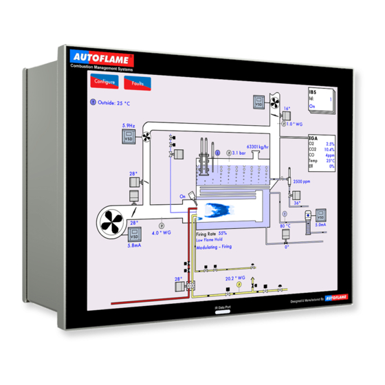
    The Mk8 MM Controller is a Micro-Modulating system that offers comprehensive control over industrial and commercial boiler/burners. With the Mk8 MM, it is possible to control all boiler processes from a single 12.1” multi-touch screen interface without any added module. It is ideal for steam and water boilers (watertube or firetube), kilns and steam generators.
  • Page 14: Mk8 Mm Main Features

    Mk8 MM Overview, Specifications and Wiring 1.1.1 Mk8 MM Main Features • Fuel/Air ratio control 12.1” Full colour touch screen • • 120V or 230V standard operation 50/60Hz Controls up to 5 servomotors and 2 variable speed drives (VSD/ VFD) •...
  • Page 15: Overview Of Micro-Modulation (Mm)

    The Micro-Modulation module is the basic building block of the Autoflame System. The Autoflame MM provides an easily programmable and flexible means of optimising combustion quality throughout the load requirement range of the burner/boiler unit whilst ensuring the temperature is accurate to within 1°C (°F) and...
  • Page 16: Fixing Holes And Dimensions

    Mk8 MM Overview, Specifications and Wiring 1.1.3 Fixing Holes and Dimensions Mk8 MM Manual Page | 16...
  • Page 17: Wiring Schematic

    Mk8 MM Overview, Specifications and Wiring Wiring Schematic 1.2.1 Main Board Mk8 MM Manual Page | 17...
  • Page 18: Expansion Board

    Mk8 MM Overview, Specifications and Wiring 1.2.2 Expansion Board If in doubt, Check with Autoflame Engineering Department Mk8 MM Manual Page | 18...
  • Page 19: Fuse Ratings

    Mk8 MM Overview, Specifications and Wiring 1.2.3 Fuse Ratings Fuse Rating Spare Part Number 6.3A (T) FU10026 Fuse 1 protects the mains input to the MM, including the mains output terminals 50 – 64. 2A (T) FU10034 Fuse 2 protects the power supply (terminal 69) for the servomotors, alarm and 2 port valve. If this fuse blows, error ‘Triac Power Supply Error (Check F2)’...
  • Page 20: Electrical Specifications

    4. Low voltage cables should be screened cable as specified in section 1.3.3. 5. The burner ‘High Limit Stat’ must be a manual reset type. 6. All external safety devices that require manual reset must be reset external to the Autoflame system and prior to completing the recycling interlock.
  • Page 21: Expansion Board Inputs And Outputs

    Mk8 MM Overview, Specifications and Wiring 1.3.2 Expansion Board Inputs and Outputs Outputs: 120/230 V All outputs with the exception of PF are switched neutrals 250mA Must be connected through contactor 250mA Must be connected through contactor 100mA (alarm indicator)
  • Page 22: Cable Specifications

    • • STC OS1P24 Samples are available upon request. Low voltage and data cable can be ordered directly from Autoflame Engineering, please contact Autoflame Sales. When using a VSD, please review the manufacturer’s guidelines on installations to prevent EMC including the recommendations for reactors and filters.
  • Page 23: Mm Terminals Description

    Digital communications connections to an Autoflame IR scanner 31, 32 Digital communications connections to an Autoflame air pressure sensor and/or Autoflame gas pressure sensor 0V supply to an Autoflame air pressure sensor and/or Autoflame gas pressure sensor Mk8 MM Manual Page | 23...
  • Page 24 Mk8 MM Overview, Specifications and Wiring +12V supply to an Autoflame air pressure sensor and/or Autoflame gas pressure sensor Signal inputs from Autoflame oil pressure sensor 0V supply to an Autoflame oil pressure sensor and/or Autoflame IR scanner +13.5V supply to an Autoflame oil pressure sensor and/or Autoflame IR scanner...
  • Page 25 Mk8 MM Overview, Specifications and Wiring Switched neutral – drives channel 1 servomotor clockwise Switched neutral – drives channel 1 servomotor counter clockwise Switched neutral – drives channel 2 servomotor clockwise Switched neutral – drives channel 2 servomotor counter clockwise Switched neutral –...
  • Page 26: Expansion Board Terminals Description

    Mk8 MM Overview, Specifications and Wiring 1.3.5 Expansion Board Terminals Description All terminals marked S are internally connected. They are provided for connections to the various screened cables. 0V supply to top blowdown and feed water servomotors Signal from feed water servomotor, indicating position...
  • Page 27 Mk8 MM Overview, Specifications and Wiring 0V supply to TDS probe 3T+, 3T- Digital communication connections from TDS probe +9V supply to capacitance probe 1 0V supply to capacitance probe 1 1T+, 1T- Digital communications connections from capacitance probe 1...
  • Page 28 Mk8 MM Overview, Specifications and Wiring Unused – do not connect Switched neutral – top blowdown contactor Switched neutral – drives top blowdown servomotor clockwise Switched neutral – 1 low water visual alarm Switched neutral – 1 low/ high water audible alarm Switched neutral –...
  • Page 29: Connection Between Mk8 Mm And Mk8 Ega Evo

    Mk8 MM Overview, Specifications and Wiring Connection Between Mk8 MM and Mk8 EGA EVO Mk8 MM Manual Page | 29...
  • Page 30: Connection Between Mk8 Mm And Mk8 Dti

    Mk8 MM Overview, Specifications and Wiring Connection Between Mk8 MM and Mk8 DTI Mk8 MM Manual Page | 30...
  • Page 31: Sequencing Connection Diagram

    Mk8 MM Overview, Specifications and Wiring Sequencing Connection Diagram Mk8 MM Manual Page | 31...
  • Page 32: Standards

    AS 4630–2005 • • FM 7610 FM 7710 • The Mk8 MM has been manufactured in conformance with the applicable design, manufacturing and inspection requirements of EU Regulation (EU) 2016/426 and ISO 9001:2015 quality system. Mk8 MM Manual Page | 32...
  • Page 33: Options And Parameters

    The Options, Parameters and Expansion Options must only be changed by factory trained and certified technicians who have a thorough appreciation of the Autoflame combustion systems and the combustion process in general. Any person changing these settings without the correct factory training and understanding of the boiler plant may place themselves and others in a potentially dangerous situation.
  • Page 34 “Enter Commissioning Password” is displayed. Use the keypad to enter the password, then press . Press on to change the value of an incorrect entry. Note: The commissioning password should not be distributed to anyone who is not a factory trained and a certified engineer. Mk8 MM Manual Page | 34...
  • Page 35 View fault logs, system log and diagnostics • • View fuel commission data Note: The Times Commissioned is for the total system and will increment with every fuel commission, single point change and commission data upload. Mk8 MM Manual Page | 35...
  • Page 36 To set all the options, parameters and expansion options to the default values and erase the commissioning data, set option/ parameter 160 to 5. The MM will then automatically restart and go into Commission mode. Mk8 MM Manual Page | 36...
  • Page 37 The value of ‘n’ is the number of seconds set in this option; if set to 0, there will be no integral control. Disabled 1 – 250 Seconds Mk8 MM Manual Page | 37...
  • Page 38 2 or 3 in online changes, going through single point change, and added trim data for each fuel-air position. Not optioned Monitoring only Applies trim Applies trim, combustion limits tested Mk8 MM Manual Page | 38...
  • Page 39 If the current CO value is above this offset limit from the commissioned value, an alarm/ warning (see option 13) will occur, for option 12 set to 3. Disabled 1 – 200 1 – 200 ppm CO Mk8 MM Manual Page | 39...
  • Page 40 MM. The MM will continue to fire to meet the previous required setpoint. 5 – 9990 F, PSI or 0.1 bar or 0.01 bar for low pressure sensor (depends on load detector set in option 1 and metric/imperial units set in parameter 40) Mk8 MM Manual Page | 40...
  • Page 41 Disabled 1 - 15 F, PSI or 0.1 bar or 0.01 bar for low pressure sensor (depends on load detector set in option 1 and metric/imperial units set in parameter 40) Unused Mk8 MM Manual Page | 41...
  • Page 42 9 should be set to 0. For setting 2, option 9 should be set to 1 or 2. Disabled Enabled, load sensor not shown Enabled, load sensor shown Firing Rate Limiter Mk8 MM Manual Page | 42...
  • Page 43 MMs is equal to or greater that this limit, the Master MM will stop modulating and wait for the slaves to catch up. When the difference reduces to less than or equal to 5%, the Master starts modulating again. Disabled 1 – 20 1% - 20% Mk8 MM Manual Page | 43...
  • Page 44 57 is set to 2. If the fuel flow exceeds this limit for 5 seconds, then a warning will appear. Disabled 1 – 500 0.1% - 50.0% of high-fire fuel flow Mk8 MM Manual Page | 44...
  • Page 45 MM: Continuous Pilot Shut Off Timer If continuous pilot is enabled (see option/ parameter 111), then after this timer has elapsed when in continuous pilot firing, the burner will go off. Disabled 1 – 1440 Minutes Mk8 MM Manual Page | 45...
  • Page 46 F, PSI or 0.1 bar or 0.01 bar for low pressure sensor (depends on load detector set in option 1 and metric/imperial units set in parameter 40) MM: Maximum Outside Temperature 0 – 145 Value 80 = 40 C or 40 F (see parameter 40) Mk8 MM Manual Page | 46...
  • Page 47 F, PSI or 0.1 bar or 0.01 bar for low pressure sensor (depends on load detector set in option 1 and metric/imperial units set in parameter 40) MM: Channel 1 Servo Control Method Autoflame Servo Motor, 0.1 degree control Autoflame Servo Motor, 0.5 degree control Industrial Servo Motor, 0.1 degree control Industrial Servo Motor, 0.5 degree control...
  • Page 48 MM: Input Units Displayed, VSD Channel 6 Selected input signal Hertz MM: Input Low Speed to MM from VSD Channel 6 0 – 200 Hertz MM: Input High Speed to MM from VSD Channel 6 0 – 200 Hertz Mk8 MM Manual Page | 48...
  • Page 49 If options 110 – 160 are not identical with parameters 110 – 160, then the MM will go straight to Commissioning Mode and an option/ parameter conflict message will appear. Mk8 MM Manual Page | 49...
  • Page 50 This is the time period after the second safety phase for interrupted pilot or after the pilot proving phase for intermittent pilot, where the flame is checked, before going to normal firing/modulation. 5 – 20 Seconds Mk8 MM Manual Page | 50...
  • Page 51 VSDs are moving to the purge position, then a lockout will occur after this timeout set in this option has elapsed. This does not apply to any requirements on purge timing such as any additional proving inputs. Disabled 1 – 3600 Seconds Mk8 MM Manual Page | 51...
  • Page 52 BC: Fuel Pressure Sensor Mode – Fuel 1 Gas: For setting 1, valve proving and pressure limits are checked by an Autoflame gas sensor. For setting 2, low pressure limit can be checked by external pressure switch. For setting 3, the system will wait for a mains voltage input on terminal 55 to confirm that the VPS test is completed.
  • Page 53 The NFPA post-purge will occur under any normal shutdown or lockout at any point in firing. Purge time in seconds Purge time in minutes NFPA post-purge in seconds NFPA post-purge in minutes Mk8 MM Manual Page | 53...
  • Page 54 This is the minimum air pressure that must be detected by the MM during purge, when using an Autoflame air pressure sensor. If this is set to 0, then MM will look for the minimum air pressure set in option/ parameter 149.
  • Page 55 This is the minimum air pressure that must be detected by the MM during normal firing and during purge when option/ parameter 141 is set to 0, when using an Autoflame air pressure sensor. See parameter 43 for air pressure display units.
  • Page 56 Clear all commissioning data, options and parameters Reset all options to default values Reset all parameters to default values Reset all safety options and parameters to default values Reset all expansion options to default values Mk8 MM Manual Page | 56...
  • Page 57: Parameters

    To set all the options, parameters and expansion options to the default values and erase the commissioning data, set option/ parameter 160 to 5. The MM will then automatically restart and go into Commission mode. Mk8 MM Manual Page | 57...
  • Page 58 2.0% - 7.5% EGA: Trim Reset Angular Rate This is the change time in the fuel valve angle per minute that will reset the trim correction. 0 – 900 0.0 – 90.0 degrees per minute Mk8 MM Manual Page | 58...
  • Page 59 Internal High Limit Setpoint is used to define an absolute shutdown setpoint that also operates in commission mode as well as normal running mode. Disabled 1 – 9990 F, PSI or 0.1 Bar or 0.01 Bar Mk8 MM Manual Page | 59...
  • Page 60 Code 2 MM: Display Units Metric units Imperial units MM: Gas Pressure Units This will set the units displayed for the Autoflame gas pressure sensor optioned. Note, PSI units are not available for sensor MM80006. mbar inWG MM: Oil Pressure Units This will set the units displayed for the Autoflame oil pressure sensor optioned.
  • Page 61 If a custom logo is stored on the data micro-SD card in the MM, then after this timer in standby mode, the custom logo will appear on the screen. Disabled 1 – 3600 Seconds Mk8 MM Manual Page | 61...
  • Page 62 If enabled, terminals 7, 8, and 9 are used for external required setpoint. The range and filtering of the input is set in parameters 69 and 70. The required setpoint range is set in options 30 and 31. Disabled Enabled Unused Unused Mk8 MM Manual Page | 62...
  • Page 63 Enabled MM: Bluetooth Module Enables/disables the on-board Bluetooth module for the purpose of connectivity with the Autoflame Download Manager software. See Autoflame PC Software Guide. To enable connectivity via the IR port, this option must be disabled, Bluetooth and IR cannot be used at the same time.
  • Page 64 Graceful shutdown cannot be used with assured low fire shut off in parameter 100. Cannot be used with DFOM or COF (option/parameter 131 setting 1 & 2). Disabled Enabled Mk8 MM Manual Page | 64...
  • Page 65 0 inWG (disabled) – 537.777 inWG 0 PSI (disabled) – 19.435 PSI MM: Online Changes Password Code 1 0 – 255 Code 1 MM: Online Changes Password Code 2 0 – 255 Code 2 Mk8 MM Manual Page | 65...
  • Page 66 If options 110 – 160 are not identical with the parameters 110 – 160, then the MM will go straight to Commissioning Mode and an option/ parameter conflict message will appear. Mk8 MM Manual Page | 66...
  • Page 67: Commissioning Procedure

    The commissioning procedure as described must be strictly adhered to. Anybody commissioning an MM must be trained in operating combustion equipment safely. The Autoflame products must only be installed, set up, commissioned and adjusted by an Autoflame certified technical engineer.
  • Page 68: Installation Checks

    The reliability of the equipment may be impaired if used in environments where strong electromagnetic fields exist e.g. if the equipment is installed in a boiler house where radio systems exist then additional EMC (Electro Magnetic Compatibility) measures may have to be considered. Please contact Autoflame for more information.
  • Page 69: Servomotors

    Commissioning Procedure Servomotors Autoflame supply three standard sizes of servomotors – small, large and industrial, which can be used for all channels. Autoflame fuel valves require small or large servomotors only. Both small and large servomotors can be configured to drive clockwise or counter clockwise to open a valve or damper. Servomotors can be installed in any orientation;...
  • Page 70: Servomotor Feedback Voltage

    0.21V DC when the reading on the display is 0 . The same can be done for when the servomotor is at 96.0 where the voltage will be 3.6V. 3.3.3 Servomotors – Direction Change Mk8 MM Manual Page | 70...
  • Page 71: Servomotors With Autoflame Valves

    Commissioning Procedure 3.3.4 Servomotors with Autoflame Valves On threaded valves, the pin on the top of the valve is 90 degrees opposite from the position of the butterfly valve. On flanged valves, the pin on the top of the valve is in line with the position of the butterfly valve.
  • Page 72: Commissioning Fuel And Air Positions

    Note: If a fault occurs, the boiler goes above the high limit stat or power is lost to the MM during commissioning, no data is stored. The points entered are only stored within the MM once the commission has been completed. Mk8 MM Manual Page | 72...
  • Page 73: Starting Commissioning

    Figure 3.4.1.i shows the Commissioning screen. In the Commissioning screen, the 7 channel positions will be shown, with the unused channels greyed out. Once the MM goes through its internal relay checks and VPS (if optioned), the message ‘Select Commissioning’ will display. Mk8 MM Manual Page | 73...
  • Page 74: Enter Closed Position

    Incorrect calibration can cause serious injury or death. Press to store the CLOSED position. The burner motor output T58 will energise at this point. A message will then be displayed ‘Enter OPEN Position.’ Mk8 MM Manual Page | 74...
  • Page 75: Enter Open Position

    OPEN position simultaneously. This is normally 90.0 for Autoflame gas butterfly valves and burner air dampers, but may be set to less than 90.0 if there are mechanical stops/limits on third party valves. Channels 5 and 6 cannot be adjusted at this stage, its calibration is dictated by the drive set-up and relevant options.
  • Page 76: Set Up Start Position

    START position, where a light off can take place. These fuel and air positions are not stored permanently as it is just a light-off position to put a flame in the boiler and begin the commissioning process. Mk8 MM Manual Page | 76...
  • Page 77: Phase Hold

    WARNING: IT IS THE RESPONSIBILITY OF THE FACTORY TRAINED TECHNICIAN TO ENSURE THAT USE OF THE PHASE HOLD FACILITY DOES NOT LEAD TO A HAZADOUS SITUATION. FAILURE TO DO SO WILL RESULT IN SERIOUS EQUIPMENT DAMAGE, CRITICAL INJURY OR DEATH. Mk8 MM Manual Page | 77...
  • Page 78: Add Trim Data During Commissioning

    GOLDEN START, FGR START and START positions, the trim data will also need to be saved for the fuel rich and air rich trim conditions. The message ‘Waiting for EGA readings’ will display. Figure 3.4.6.i Sampling Press on the EGA tab to display the EGA readings. Mk8 MM Manual Page | 78...
  • Page 79 Note: If the MM has not been enabled for trim during commissioning, this can be added later by setting option12 for trim, and going into Single Point Change to add trim to each point, see section 3.7. Mk8 MM Manual Page | 79...
  • Page 80: Commissioning Vsd

    The minimum feedback variation applies to both the upper and lower limits so the total commission must allow for the two combined. Mk8 MM Manual Page | 80...
  • Page 81: Set Golden Start Position

    Alternatively, to just add the Golden Start position and not go through the whole commissioning procedure, press on the home screen, and once the system has gone through its internal relay tests the Mk8 MM Manual Page | 81...
  • Page 82 Golden Start can be set in Option 29 to start from first ignition instead of after the main flame stabilisation phase has passed, this is particularly useful for briefly providing additional fuel when starting an oil flame with direct spark (no pilot mode – see option 111) Mk8 MM Manual Page | 82...
  • Page 83: Set Fgr Position

    FGR START position and continue with the full commissioning procedure in section 3.4.10. Alternatively, to just add the FGR Start position and not go through the whole commissioning procedure, press on the home screen, and once the system has gone through its internal relay tests the Mk8 MM Manual Page | 83...
  • Page 84 FGR can be set as a Timer, Offset or Temperature Threshold (see options 48, 49 and 50). Note: Golden start takes priority over FGR. Once the golden start timer has finished, the servomotors will go straight to the FGR start position. Mk8 MM Manual Page | 84...
  • Page 85: Set High Position

    0.5° up/down from the previous point initially, before entering the next point, the fuel. Press store this HIGH position. WARNING: IT IS THE RESPONSIBILITY OF THE COMMISSIONING ENGINEER TO ENSURE THAT THE FLAME IS SAFE AND THERE IS A GOOD COMBUSTION AT ALL TIMES DURING COMMISSIONING. Mk8 MM Manual Page | 85...
  • Page 86: Set Inter Position

    There must be a minimum of 3 INTER points entered on the fuel-air curve, and a maximum of 18. Points can be added/removed in Single Point Change mode (see section 3.6). Continue this process until all the required INTER points have been entered. Mk8 MM Manual Page | 86...
  • Page 87: Set Inter Or Start Position

    (and VSD) to the START/ LOW FIRE position, and then press to store this. Note: If Golden Start or FGR Start are in use, the Start position is only used for Low Fire. Mk8 MM Manual Page | 87...
  • Page 88: Save Commission

    Note: If commissioning a fuel for the first time the default required setpoint will be 2.0bar/20PSI/20 C/20 The burner will shut down at commission completion due to the low default required setpoint. Go to the Status screen to change the required setpoint. Mk8 MM Manual Page | 88...
  • Page 89: Fuel Flow Metering

    MW if metric of MMBTu/hr if imperial. On the Mk8 MM, fuel flow metering can be taken as the values entered in the fuel flow commissioning screen from the fuel flow meter or through a 4-20mA signal input on terminals EX- and EX+.
  • Page 90 Commissioning Procedure Figure 3.5.1.i System Configuration Screen On the System Configuration screen press . You will be prompted to enter the Online Change password. Press to access the Online Changes screen. Mk8 MM Manual Page | 90...
  • Page 91: Commissioning Fuel Flow Through 4-20Ma Feedback

    If fuel flow metering is enabled through using 4-20mA feedback on terminals EX- and EX+, the heat value will automatically get populated according to the analogue signal at that fuel valve position. After each heat value is displayed, press enter to go to the next fuel flow point. Mk8 MM Manual Page | 91...
  • Page 92: Calorific Fuel Data

    Volume correction factor per 0.00046 0.00046 0.00039 0.00039 0.00038 1°F Btu/U.S. gallon (US standard) 140,000 150,000 160,000 Lb/U.S. gallon (US standard) 7.01 7.01 % lighter than water 1 u.s. Gallon of oil / ft of air 1402 Mk8 MM Manual Page | 92...
  • Page 93: Conversion Factor For Imperial Gas Flow Meters

    (Pressure of gas at meter x 0.00228) + (0.948 – (height above sea level x 0.0001075)) Example: As above but 250 m above sea level: Correction factor = (58x0.00228) + (0.948 – (250 x 0.0001075)) = 1.05 Mk8 MM Manual Page | 93...
  • Page 94: Gas Volume Conversion Factors

    280.059 37.36 373.515 1.3951 5.777 4064 298.73 39.851 398.416 1.4201 6.138 4318 317.4 42.341 423.317 1.4452 6.499 4572 336.071 44.832 448.218 1.4703 6.86 4826 354.741 47.323 473.119 1.4953 7.221 5080 373.412 49.813 498.02 1.5204 Mk8 MM Manual Page | 94...
  • Page 95 6. For natural gas, the calorific value is typically 1000 Btu/ft3. To obtain the firing rate of the boiler at standard reference conditions multiply the volume at reference conditions by 1000. Represented as an equation: Firing rate = (Measured Volumetric flow per minute x 60 x Conversion factor x 1000) Btu/hr Mk8 MM Manual Page | 95...
  • Page 96: Gas/ Air Pressure Commission

    Note: For applications where VPS is required after burner shutdown only, the option/parameter 129 should be set to 0 when doing the first gas sensor commission on the system to store the valve proving gas pressure. During normal running, option/parameter 129 can be set to 1. Mk8 MM Manual Page | 96...
  • Page 97: Single Point Change

    Single Point Change mode. Select the point to be edited or added trim to by pressing to go up and down the fuel curve, then press The Status screen will display the message ‘Select change to make’. Mk8 MM Manual Page | 97...
  • Page 98 To delete a point on the curve, move to a point below that one to be deleted and press Press to confirm the change. Note: It is not possible to delete LOW or HIGH FIRE positions or have less than 3 INTER points. Mk8 MM Manual Page | 98...
  • Page 99 If a point is overwritten, the trim data is cleared and the trim data will need to be added. Press to remove the point; there must be a minimum of 3 INTER points. Mk8 MM Manual Page | 99...
  • Page 100 Commissioning Procedure To add trim data to a point press , see section 3.4.6. Figure 3.7.iv Single Point Change – Trim The MM will store the trim values for this position. Mk8 MM Manual Page | 100...
  • Page 101 The fuel flow commissioning must be entered (again) if the following changes are made in single point change HIGH or START position is changed. • EGA trim data has been added. • • Points have been added. Please see section 3.5 Fuel Flow Commissioning. Mk8 MM Manual Page | 101...
  • Page 102: Online Changes

    Reset fault logs • • Reset system log Reset bottom blowdown log • • Reset boiler configuration Reset run times • Reset steam flow metering • Restart MM if the burner is in standby • Mk8 MM Manual Page | 102...
  • Page 103: Setpoint Schedule

    MM screen in Online Changes mode once the MM has been commissioned Setpoint Schedule is an MM Expansion Feature that requires the purchase of an unlock code (part # MK8100), this must be uploaded to the MM via Autoflame Download Manager software, please see Autoflame Software Guide for more details.
  • Page 104 To set a variable or gradual setpoint for a specific period of time, tap on the red bar, its colour will change to blue, specify the start and end setpoints using the up and down arrows. After setting the setpoint, click to store the settings or click to exit without saving the changes. Mk8 MM Manual Page | 104...
  • Page 105 Commissioning Procedure Figure 3.9.2. iii: Different setpoints configured throughout the week using Setpoint Schedule Mk8 MM Manual Page | 105...
  • Page 106: Fuel Output Modes & Changeover Options

    FUEL OUTPUT MODES & CHANGEOVER OPTIONS Overview The Mk8 MM has the capability of controlling multi-fuel applications in various ways; it offers the possibility of commissioning up to 4 different fuels as well as offering 3 different ways of switching between fuels.
  • Page 107: Fuel Output Modes On The Mk8 Mm

    MM via IR Lead using Autoflame Download Manager software (version 8.13 and above). COF is available only on Revision 4 of the Mk8 MM, for more information please contact Autoflame.
  • Page 108: Single Fuel Output Mode (Sfom)

    Single Fuel Output Mode (SFOM) Single Fuel Output Mode (SFOM) is the standard (default) mode of operation for the Mk8 MM, it can be selected by setting Option/ Parameter 131 to 0. On this mode it is possible to configure and commission 4 fuels utilising the main set of fuel outputs on the MM using changeover relays.
  • Page 109: Dual Fuel Output Mode (Dfom)

    Valve proving may be used with or without a vent valve (Option 130 setting 2 or 3). If 2 liquid fuels are configured in DFOM, it is not possible to use pressure sensors for both fuels at the same time. Mk8 MM Manual Page | 109...
  • Page 110: Commissioning In Dfom

    If the current fuel is reselected while the burner is still firing the fuel change shutdown can be cancelled. Once the MM reaches the Recycle/Standby state, the fuel changeover takes place and the burner will restart on the newly selected fuel. Mk8 MM Manual Page | 110...
  • Page 111 Fuel Output Modes and Changeover Options Figure 4.4.4: Fuel Changeover Process in Dual Fuel Output Mode Mk8 MM Manual Page | 111...
  • Page 112: Fuel Change On The Fly (Cof)

    MM will operate as already described for Dual Fuel Output Mode, shutting down the burner for a fuel change. If COF is not enabled, the MM will change fuel in the same way as in Dual Fuel Output Mode, shutting down the burner and restarting on the newly selected fuel. Mk8 MM Manual Page | 112...
  • Page 113: Checks Before Cof Can Take Place

    VSD signal output on both fuels when commissioning the fuels in Dual Fuel Output Mode, this is to ensure that sufficient amount of air is present for both fuels to fire at the COF Changeover Position. Mk8 MM Manual Page | 113...
  • Page 114: Cof Fuel Changeover

    MM Phase: Fuel Changeover – COF 1 Safety • The new fuel main valves are opened starting its main flame. The two fuels fire together for the main flame proving time (Option 117). Mk8 MM Manual Page | 114...
  • Page 115: Checks After Cof Fuel Changeover

    This verifies that no leaks are present on the non-running fuel valves. Failure of valve proving will cause a lockout that stops the burner. Mk8 MM Manual Page | 115...
  • Page 116: Continuous Pilot With Cof

    When fuel selection is changed, the MM moves to the restart position of the selected fuel, inhibiting the burner from starting until the new position is reached. Please refer to section 5 for full details about Continuous Pilot. Mk8 MM Manual Page | 116...
  • Page 117 Fuel Output Modes and Changeover Options Figure 4.5.6: Fuel Changeover on the Fly Process Mk8 MM Manual Page | 117...
  • Page 118: Gas Pressure Sensors And Valve Proving In Dfom With Cof

    (Option 13 setting 0 or 3). Fuel pressure limits continue to be tested for the currently firing fuel as normal, including when other operations such as valve proving are taking place on the other fuel. Mk8 MM Manual Page | 118...
  • Page 119: Limitations Of Dfom And Cof

    Piggyback valve arrangement, separate servomotor is required for each fuel. Dual Fuel Output Mode and COF features will not be displayed on the Mk7 DTI, only Mk8 DTI is able • to display these features. Mk8 MM Manual Page | 119...
  • Page 120: Pid Control

    PID Control PID CONTROL The standard control algorithm used by the Mk8 MM to control the fuel/air ratio is PID control; Proportional- Integral-Derivative control. The control algorithm compares the actual measured temperature or pressure and compares it to the user specified setpoint temperature or pressure. Depending on the measured and setpoint values, the MM’s PID control will then either modulate the burner up or down.
  • Page 121: Integral Control

    “n” seconds, “n” is specified in option 7, the default is 60s. Figure 5.2.i Integral Control (Parameter 48 = 0.8, Integral operation band of P-Band) Mk8 MM Manual Page | 121...
  • Page 122: Derivative Control

    38, and the response sensitivity as a percentage of firing rate increase or decrease is defined in option 39. Figure 5.3.i Derivative Control NOTE: The derivative action occurs at all points outside of the deadband. This includes within the proportional band. Mk8 MM Manual Page | 122...
  • Page 123: Mm Features

    MM is in hand mode. Hand mode can only be activated when the burner is firing. The Mk8 MM will go into hand mode when a voltage is detected on Terminal 94 or when the hand mode button is pressed in the Status screen.
  • Page 124 MM Features Figure 6.1: Mk8 MM status screen Mk8 MM Manual Page | 124...
  • Page 125: Using 4-20Ma Servomotors

    The Mk8 MM channels which can be controlled using an external 4-20mA servomotor include channels 1, 2, 3, 4 and 7. Any or all of the 5 servomotor channels available on the Mk8 MM can be independently configured to use an externa 4-20mA servomotor or an Autoflame servomotor.
  • Page 126: Wiring

    MM Features 6.2.3 Wiring Mk8 MM Manual Page | 126...
  • Page 127: Settings

    It is possible to use a combination of external 4-20mA servomotors and Autoflame servomotor, for example, channel 1 can be set as an Autoflame servomotor and channel 2 can be set as an external 4-20mA servomotor. The degree of accuracy when using an external 4-20mA servomotor via a Universal IO module is 0.5°, in comparison to the accuracy level of 0.1°...
  • Page 128: Flame Detection Using Flame Switch

    MM Features Flame Detection Using Flame Switch The Mk8 MM can utilise an external flame switch for the purpose of flame detection. To configure operation with a flame switch, option/parameter 122 can be set to 1. The operation of Terminals 85 and 86 will be as follows: •...
  • Page 129: Continuous Pilot

    Continuous Pilot The Mk8 MM has a continuous pilot (pilot relight – return to pilot) feature. If continuous pilot is enabled, when the burner goes above its off differential of the required setpoint, the burner will continue to fire with only the pilot valves energised.
  • Page 130: Continuous Pilot With Interrupted Pilot Sequence

    Pilot Valves On Stat Circuit T53 Circuit Ignition Off Made? Made? Main Valves On Pilot Valves Off Firing Stat Circuit Main Valves Off Pilot Valves Off Made? T53 Circuit Made? Return to Start Post purge Mk8 MM Manual Page | 130...
  • Page 131: Continuous Pilot With Intermittent Pilot Sequence

    Pilot Valves On Stat Circuit T53 Circuit Ignition Off Made? Made? Main Valves On Firing Stat Circuit Main Valves & Pilot Valves Off Made? Pilot Valves Off T53 Circuit Made? Return to Start Post purge Mk8 MM Manual Page | 131...
  • Page 132: Load Sensor Value Calibration

    For example, if the actual temperature was showing as 91°C on the MM, but the true temperature was 79°C, change the value in parameter 29 until the correct temperature adjustment has been made. Figure 3.9.1.i shows the load sensor adjusted by 96.0% to display 79°C. Figure 6.5: Load Sensor Adjusted Mk8 MM Manual Page | 132...
  • Page 133: External Modulation

    MM uses the internal ‘Required’ setpoint value. When a line voltage input is provided on terminal 87, the MM uses the internal ‘Reduced’ setpoint value. A second setpoint input (T87) may be used to select the reduced setpoint. Mk8 MM Manual Page | 133...
  • Page 134: Start Position Interlock And Purge Position Interlock

    Figure 6.9: End Switch Wiring Schematic End Limit Switches are mounted on the end of bespoke valves (please contact Autoflame regarding bespoke valve manufacture) which are attached to the air and fuel valve and commissioned depending on the use of the End Limit Switches.
  • Page 135: Purge Pressure Proving/ Purge Hold

    Caution: When it is desired to end the continuous purge, it is necessary to disable the burner prior to turning the manual switch back to the normal position. Otherwise the burner will start up. Mk8 MM Manual Page | 135...
  • Page 136: No Pre-Purge

    Loss of power to the MM • • VPS checks have failed MM has been in standby for 24 hours or more • Note: Pre-purge is only available on fuels which are optioned as gaseous. Mk8 MM Manual Page | 136...
  • Page 137: Intelligent Boiler Sequencing

    Any MM interconnected may be selected as the lead boiler for the sequencing. The lead boiler is identified by: 1. Connecting a mains voltage onto Terminal 88 (only on the Mk8 MM) 2. Selecting Lead boiler in the IBS screen 3.
  • Page 138: Hot Water Example

    Intelligent Boiler Sequencing - IBS 7.1.1 Hot Water Example Mk8 MM Manual Page | 138...
  • Page 139: Single/ Multi-Burner Examples

    Intelligent Boiler Sequencing - IBS 7.1.2 Single/ Multi-Burner Examples Boiler 1 Boiler 2 Boiler 3 Mk8 MM Manual Page | 139...
  • Page 140: Ibs Communications

    Intelligent Boiler Sequencing - IBS 7.1.3 IBS Communications Mk8 MM Manual Page | 140...
  • Page 141: Sequencing Options And Parameters

    Sequence scan time set when unit goes offline Number of boilers initially on Modulation timeout Highest MM ID Hot water sequencing IBS change down threshold IBS change up threshold Shuffle sequencing Expansion Option Description Sequencing/DTI or Modbus function Mk8 MM Manual Page | 141...
  • Page 142: Hot Water Sequencing

    For hot water sequencing, a temperature detector must be fitted to all the MMs (only Master MMs in Multi- Burner operation if option 14 is set to 1 – Mk8 MM only) and option 1 must be set to 0 or 5.
  • Page 143: Two Port Valve Operation

    This facility ensures that boilers that are switched ‘offline’ do not contribute return temperature water to the flow header thereby diluting the flow temperature to the building. Mk8 MM Manual Page | 143...
  • Page 144: Steam Sequencing

    The burner can also be controlled by a (warming) thermostat fitted in the boiler shell, wired to terminal 82 (see option/ parameter 156). Off – the burner does not fire. • Mk8 MM Manual Page | 144...
  • Page 145: Low Pressure Steam Sequencing

    40 must be set to low pressure steam sequencing. For the Mk8 MM, a 230V/ 120V input on terminal 93 (see option 79) will initiate the warming for that lag boiler, and this will fire according to the warming interval timings in options 53 and 54.
  • Page 146: Troubleshooting - Sequencing

    • Testing Communications with an LED When having communications problems between Autoflame MMs, a simple test with a standard 5V LED can confirm if they are due to hardware or wiring problems. Take a standard 5V LED and wire it into terminals 27 and 28 of the MM ensuring correct polarity (black connected to the negative leg of the LED).
  • Page 147: Multi-Burner Operation

    9 Slave MMs can be used to control up to 10 burners in total. Note: All MMs in a multi-burner operation must have identical version of the software (MM, BC & DI). • Fuel Change on the Fly (COF) feature cannot be used with Multi-Burner operation. • Mk8 MM Manual Page | 147...
  • Page 148: Configuring Multi-Burner Operation

    8.2.1 Wiring Terminals 23 and 24 on the Mk8 MM are used for Multi-Burner communications, a screen must be connected at one end. The connection must be made as per the diagram below: Mk8 MM – ID 1 (Master MM) Mk8 MM –...
  • Page 149: Options And Parameters

    Multi Burner Operation 8.2.2 Options and Parameters The following table shows the Mk8 MM options relevant to implement Multi-Burner operation. Option Description Multi-Burner Function Multi-Burner ID Multi-Burner Highest Slave ID 8.2.3 Commissioning in Multi-Burner Operation In Multi-Burner operation, the MMs can be commissioned simultaneously or individually.
  • Page 150: Multi-Burner Operation Options

    If there is a loss of communications between the MMs, all of them will open their internal stat and a ‘multi- burner communications fault’ alarm will occur. They will all shut down and only start once all are communicating via the multi-burner link. Mk8 MM Manual Page | 150...
  • Page 151: Independent On Fault

    Master MM. When multi-burner MMs are setup as independent, each individual MM will go into hand or low flame hold if the input is active on its terminals 94 and 95, respectively. Mk8 MM Manual Page | 151...
  • Page 152: Multi-Burner With Water Level Control

    In order to meet BS EN 12953, the minimum requirements for safe water level control are to have an independent high integrity self-monitoring low water cut off, in addition to the water level control. When using the Autoflame water level control, an auxiliary 2nd low probe must be fitted to meet these requirements in the Mk8 MM Manual...
  • Page 153: Multi-Burner With Ega

    In critical situations where one of the MMs is in fault condition, single burner firing can be used. However, it is recommended that the EGA is optioned to monitor only (Mk8 MM option 12 set to 1) or completely disabled to ensure reliability.
  • Page 154: Multi-Burner With Individual Egas

    EGA option 13, the effect on other multi-burner systems is dependent on option 43 setting. Please refer to the EGA Setup Guide for more information on setting up combustion limits. Mk8 MM Manual Page | 154...
  • Page 155: Multi-Burner External Modulation

    If the MMs are switched on for external modulation and a Slave MM has a lockout, the Master MM will continue to fire with external modulation. Once the fault has been reset, they will sync when the Slave MM reaches firing status and continue with external modulation. Mk8 MM Manual Page | 155...
  • Page 156: Expansion Features

    Expansion Features EXPANSION FEATURES The Mk8 MM Expansion Features allow additional boiler operations to be controlled using the Mk8 MM. Most operations related to the boiler can be controlled using the Mk8 MM Expansion Features. The following expansion features are available on the Mk8 MM:...
  • Page 157: Water Level Control

    10.1.2 Autoflame Water Level Control Autoflame Water Level control in the Mk8 MM focuses on safety and accuracy in controlling the water level in a steam boiler. The intelligent water level control includes high water alarms, 1 low and 2 low alarms.
  • Page 158: Water Treatment

    The boiler manufacturer will specify the required TDS level in the water for that boiler. The Mk8 MM has an expansion feature which allows the system to control the TDS level in the boiler via top blowdown control, please see section 4 for top blowdown control.
  • Page 159: Water Level Control Expansion Options

    Water Level Control 10.2 Water Level Control Expansion Options The table below shows the Expansion Options used for configuring Autoflame Water Level Control as well as Analogue Water Level Control. Default Range Description WLC: Water Level Control Function For setting 1, there must be a minimum of two-level sensing elements or a conflict will appear.
  • Page 160 WLC: Second Low Probe For setting 0, it is recommended that an auxiliary second low mains input is wired to terminals 2AI. For setting 1, the Autoflame conductive second low probe is wired to terminals 4P-, 4P+, 6T- and 6T-. Please see local codes/ regulations for second low probe and auxiliary second low alarm setup.
  • Page 161 As default the servomotor is set as fully open, however this setting can be decreased to shorten the operational movement range of the servomotor. 100 – 900 10.0 – 90.0 Mk8 MM Manual Page | 161...
  • Page 162 If water does not drop to the first low level in this time period, then MM will revert back to normal run mode and cancel the shunt switch test. 30 – 600 Seconds Mk8 MM Manual Page | 162...
  • Page 163 The filter time is the rolling time period over which the capacitance probes take the water level reading. When a moving water level is detected this time period reduces in proportion linearly to the movement. 1 – 30 Seconds Mk8 MM Manual Page | 163...
  • Page 164 (at the pressure set in Exp Option 35) 0 – 2000 0 – 2000 mm WLC: Audible Alarm Timeout Period Sets the time counter for water level alarm or warning. 0 - 3600 Seconds Mk8 MM Manual Page | 164...
  • Page 165: Water Valves

    Maximum operating temperature: 235°C (455°F) Note: Autoflame water level probes are rated at maximum 16 Bar (232 PSI) and 200°C (392°F). Note: Please check Autoflame Valves and Servomotors Guide for water level valves dimensions, specifications, drawings and information on service and maintenance.
  • Page 166: Feed Water Valve Sizing

    70008 31822 21.28 1.38 8200 136.6 82011 37278 Autoflame Part No. WLCV040 – 1 ½” feed water valve water flow calculations @20°C Water Velocity Pressure Drop Across Valve Water Flow Rate Steam Flow Rate Ft/sec M/sec ∆P PSI ∆P Bar...
  • Page 167: Feed Water Control

    The feed water servomotor closed position is set by zeroing the potentiometer in Commissioning mode, however the open position is set in expansion option 16. Mk8 MM Manual Page | 167...
  • Page 168: Ways Of Level Sensing

    The MM will show the capacitance probe reading(s), the external level sensor reading, and a combined reading of the optioned analogue sensing devices, as well as the 2 low probe and auxiliary alarm inputs status. Figure 10.4.1.i Water Level Status – Combined Level Sensing Mk8 MM Manual Page | 168...
  • Page 169: Configuration

    Water Level Control 10.4.2 Configuration The following tables show the expansion options which need to be set on the Mk8 MM for the different ways of water level detection. Expansion Option Description Setting 1. One capacitance probe, external level sensor...
  • Page 170 External level sensor Probe mismatch threshold As required Capacitance probe still water threshold As required Capacitance probe filter time As required External level sensor scaling As required External level sensor filter time As required Mk8 MM Manual Page | 170...
  • Page 171 Water level control function Auxiliary alarm inputs Second low probe 18. External level sensor, 2 low probe Water level control function External level sensor External level sensor scaling As required External level sensor filter time As required Mk8 MM Manual Page | 171...
  • Page 172: Capacitance Probes

    10.5.1 Overview The Autoflame capacitance probes can be used in conjunction with the Mk8 MM to detect the water level in the boiler. The system safety is guaranteed as the level measurement is managed by two identical capacitance probes both of which measure and control to the level switching points entered at the time of commissioning.
  • Page 173: Operation

    Note: The probes must not be cut. If the probes are cut this will act as a short between the positive and negative plates of the capacitor and will stop the probes from working. Mk8 MM Manual Page | 173...
  • Page 174 Water Level Control Figure 10.5.3.ii Capacitance Probe Dimensions and Photos Mk8 MM Manual Page | 174...
  • Page 175: Installation Safety Guidelines

    Under all boiler operation codes that Autoflame is aware of, it is not permitted to install only two capacitance probes without an additional water level detection device. When the capacitance probes are installed on a boiler application in this way, the boiler must be protected using a separate auxiliary low water cut-off device.
  • Page 176 Water Level Control Figure 10.5.4.A: Capacitance Probe – Externally Mounted Pots Mk8 MM Manual Page | 176...
  • Page 177 Water Level Control Figure 10.5.4.B: Capacitance Probe – Internally Mounted Pots Mk8 MM Manual Page | 177...
  • Page 178 Water Level Control Figure 10.5.4.C: Capacitance Probe – Installation for a Water Tube Boiler Mk8 MM Manual Page | 178...
  • Page 179 Water Level Control Figure 10.5.4.D: External Probe Chamber – Recommended Dimensions Mk8 MM Manual Page | 179...
  • Page 180: Configuration

    It is recommended that the probes are not installed too close to the steam off- take and safety valve connection, but also not too close to the boiler end plates. If possible, they should be installed near the sight gauge glass. Mk8 MM Manual Page | 180...
  • Page 181: Nd Low Probe

    When used with an MM, the 2 low water alarm requires a manual reset. 10.6.3 Specifications Specifications Metric Imperial Part number SLP70001 Compatible with Mk8 MM and Mk7 MM Standalone usage Internal relay Self-checking Technology Conductivity Material Stainless Steel Coating PTFE coated...
  • Page 182 Purple If using the 2 low probe for standalone operation, then the volt-free connections must be used; the volt-free connection will be closed when water is detected and there is no system fault. Dimensions Mk8 MM Manual Page | 182...
  • Page 183: Installation And Safety Guidelines

    3.5.4, the 2 low probe can also be installed in an internally mounted pot directly into the boiler. Figure 10.6.4.i Capacitance Probes and 2 Low Probe displayed on the main Mk8 MM screen Mk8 MM Manual Page | 183...
  • Page 184: Configuration

    Water Level Control 10.6.5 Configuration The table below shows the Mk8 MM terminals allocated for the 2 low safety probe. Terminal Description Digital communication connections from 2 low resistance probe Digital communication connections from 2 low resistance probe +12V supply to 2...
  • Page 185: Analogue Water Level

    Analogue Water Level An external level sensor (4-20mA input) can be used for water level detection on the Mk8 MM. This sensor will give an analogue signal to the MM to indicate level across a 4-20mA input range. The water levels...
  • Page 186: Auxiliary Alarm Inputs

    Note: Auxiliary alarm inputs can only be used in conjunction with an analogue sensing device such as two capacitance probes or one capacitance and an external level sensor at minimum. please see section 3.4 for Ways of Level Sensing for more information. Mk8 MM Manual Page | 186...
  • Page 187: Commissioning Procedure

    Once the burner is commissioned with the Mk8 MM, the water level probes will need to be recommissioned once the boiler is up to pressure, and water in the boiler is hot enough.
  • Page 188: Setting End Of Probe Level

    VSD output if enabled in expansion option 2. Press to turn the pump off. As the water level exceeds the end of the probe, the displayed probe values will begin to change. To leave the water level commissioning process, press Mk8 MM Manual Page | 188...
  • Page 189 Allow some time for the readings to settle and then press to store these readings. Once the level has been entered, it is possible to update the commissioned readings by adjusting the water level and pressing Mk8 MM Manual Page | 189...
  • Page 190: Setting 2 Nd Low Level

    Let the readings settle and press If required, the 2 low level can be updated by adjusting the water level and pressing once the position has been stored. Mk8 MM Manual Page | 190...
  • Page 191: Setting 1 St Low Level

    Let the readings settle and press If required, the 1 low level can be updated by adjusting the water level and pressing once the position has been stored. Mk8 MM Manual Page | 191...
  • Page 192: Setting Control Point Level

    Once the water has risen to the required control point level, turn the pump off and close the valve. Let the readings settle and press If required, the control point level can be updated by then adjusting the water level and pressing once the position has been stored. Mk8 MM Manual Page | 192...
  • Page 193: Setting High Level

    Once the water has risen to the required high water level, turn the pump off and close the valve. Let the readings settle and press If required, the high water level can be updated by adjusting the water level and pressing once the position has been stored. Mk8 MM Manual Page | 193...
  • Page 194: Save Commissioning

    Water Level Control 10.9.8 Save Commissioning Figure 10.9.8.i Save Commissioning After storing or updating the high water level, press to save the commissioned water level readings. Mk8 MM Manual Page | 194...
  • Page 195 Once the water level has been commissioned, adjust the water level to reach the control point, and either press to commission the burner after the operational checks of the water level operation in section 10.9.9 has been carried out, or press to return to Commissioning Mode. Mk8 MM Manual Page | 195...
  • Page 196: Operational Checks

    Note: All local & national codes for safe operation of boiler plant must be adhered to. If in any doubt contact your local specialist authority. Mk8 MM Manual Page | 196...
  • Page 197: 10.9.10 Adjust Control Point

    The pump on/off percentages and pre-level alarms will change with the new control point. Once the control point has been adjusted, press to save, and then press to leave the Water Level Status screen. Mk8 MM Manual Page | 197...
  • Page 198: Water Level Control Functions

    For pump bypass on below switch point, the pump bypass will turn on at a percentage below the valve open range set as a switch point, and it will turn off at percentage above the switch point, set as the hysteresis from the switch point. Mk8 MM Manual Page | 198...
  • Page 199: 10.10.3 Test Outputs And Shunt Switch

    The alarm outputs and shunt switch can also be checked via the Water Level Status screen on the MM. Figure 10.10.3.i Trigger Shunt Switch Press to cycle the alarm outputs every 2 seconds. Press to check the water level alarms as described above. Mk8 MM Manual Page | 199...
  • Page 200: 10.10.4 Sudden Pressure Drop

    Without the sudden pressure drop function, the system will trigger a 1 low water level alarm as the feed water pump/servomotor would not react quick enough to maintain the water level in the boiler. Mk8 MM Manual Page | 200...
  • Page 201: Faults

    If using two capacitance probes, then two individual probes must be connected Check wiring on terminals 1P+, 1P-, 1T+, 1T-, 2P+, 2P-, 2T+ and 2T- • Alarm Aux WL Inputs Mismatch High water and 1 or 2 low auxiliary level Mk8 MM Manual Page | 201...
  • Page 202 Check wiring and screen on terminals 5T+, 5T-, 4P- and 4P+ • Alarm Second Low Probe Hardware Fault Internal check failed • Contact Autoflame approved local tech centre Alarm Permanent Test Input Input held on test terminal for more than 60 seconds Check input on terminal TST •...
  • Page 203 Warning Shunt Switch Time Expired Once shunt switch time expires, system goes to normally running If water drops after shunt switch time expires, system will generate 1 or 2 low as relevant • Mk8 MM Manual Page | 203...
  • Page 204: Top Blowdown

    It can be seen from the above that the Autoflame TDS system deals succinctly with three of the main problem areas that are encountered when designing an accurate TDS control solution.
  • Page 205: Tds, Conductivity And Temperature

    25°C (77°F) which would give a reading of 5000 micro-siemens. If the reading from the probe does not agree with this general CCC value, a correction multiplier or divider is entered into this specific probe’s memory. This is its own dedicated CCC value. Mk8 MM Manual Page | 205...
  • Page 206: Top Blowdown Expansion Options

    20 – 100 0.20 – 1.00ppm / (µS/cm) 1000 TBD: TDS Adjustment This value will automatically display the adjustment factor when the TDS probe is recalibrated during running. 10 – 999 0.010 – 9.999 Mk8 MM Manual Page | 206...
  • Page 207 100ppm below the target value, the solenoid valve or top blowdown servomotor will remain closed for the duration of the blowdown time. If the measure reading is higher than the target TDS value, the PID control will operate. 10 – 1200 Seconds Mk8 MM Manual Page | 207...
  • Page 208 100 – 900 10.0 – 90.0 ° ° TBD: TDS Alarm Level Disabled 1 – 5000 TBD: No Blowdown Idle Time Disabled 1 – 720 Minutes Mk8 MM Manual Page | 208...
  • Page 209: Tds Valves

    29 Bar (425 PSI) Maximum operating temperature: 235°C (455°F) Please check the Autoflame Valves & Servomotors guide for the full details on the bottom blowdown valve and servomotors including dimensions, drawings and information on service and maintenance. Figure 11.3.1.i TDS Valve installation example The table below shows the available TDS probe and valve assembly part numbers.
  • Page 210: Tds Probe

    Figure 11.4.1.i TDS Probe The TDS probe part number: TDS70003 • Timed pulsed top blowdown or continuous top blowdown operation selectable on the Mk8 MM. Self-cleaning design. Turbulence created during the blowdown sequence ensures that the probe • remains effectively free of scale or deposited solids that could be held in suspension.
  • Page 211: Dimensions

    Top Blowdown 11.4.2 Dimensions Mk8 MM Manual Page | 211...
  • Page 212: Installation

    11.4.3 Installation The diagram below shows the installation method for the TDS probe incorporating Autoflame’s sampling system, (all dotted components are to be supplied by the customer). Note: There must be a minimum of 3ft (0.9m) straight pipe installed from the valve, of the same diameter as the actual valve.
  • Page 213: Configuration

    Top Blowdown 11.5 Configuration 11.5.1 Wiring The table below indicates the terminals on the Mk8 MM allocated for Top Blowdown control. Terminal Description 0V supply to top blowdown and feed water servomotors Signal from top blowdown servomotor, indicating position +12V supply to top blowdown servomotors...
  • Page 214: Ways Of Controlling Tds Level

    2200ppm, the measured value would need to be 2100ppm or more for the valve to blowdown. At the end of the blowdown time, the valve will go to fully open for the sample time, to repeat the TDS control loop. Mk8 MM Manual Page | 214...
  • Page 215: Tds Timing Diagram

    For continuous TDS control the valve blows down at an angle calculated by the PI loop. For solenoid or servomotor 2-state TDS control the P band determines how long the valve remains open before closing during the blowdown time. Mk8 MM Manual Page | 215...
  • Page 216: Sample Routine

    At the start of each measurement cycle the sample is checked for polarization. This background voltage effect is taken into the conductivity calculations. Temperature and pressure are measured by the Autoflame system and this information is used to continually modify the calculated conductivity/TDS value from its calibrated point. Nominally for every 1°C increase or decrease, 2% is added or subtracted from the conductivity value.
  • Page 217: Water Hardness Monitoring

    A water hardness warning level can be set in Expansion Option 46 so that an MM alarm will be triggered if this threshold is reached. An alarm level can also be set in Expansion Option 56, this information will also be displayed in the water hardness screen. Figure 11.7 – Water Hardness Monitoring Screen Mk8 MM Manual Page | 217...
  • Page 218: Calibrating The Tds Probe

    The TDS target value is set in expansion option 42. Top blowdown control does not function when the pressure is below the offset pressure from the required setpoint which is set in expansion option 47. Figure 11.8A - Top Blowdown Screen Mk8 MM Manual Page | 218...
  • Page 219 TDS using the probe. Note: Top blowdown control does not operate when the TDS probe is being calibrated, when a fresh sample is taken or when the burner is not firing. Mk8 MM Manual Page | 219...
  • Page 220: Faults

    • • Check servomotor drives in correct direction • Check top blowdown valve is not stuck Warning Top Blowdown Reading High TDS value detected too high Check expansion option 46 and TDS value • Mk8 MM Manual Page | 220...
  • Page 221: Bottom Blowdown

    The purpose of Bottom blowdown is to remove solids which build up at the bottom of a steam boilers. In the Autoflame system, there are options to either manage the blowdowns through automatic timings, or to manually trigger them. The programmable electronic automatic blowdown ensures repeatable blowdown timings without the need of a compressed air supply.
  • Page 222: Bottom Blowdown Expansion Options

    Bottom Blowdown 12.2 Bottom Blowdown Expansion Options The table below shows the Expansion Options used for configuring Autoflame Bottom Blowdown. Default Range Description BBD: Bottom Blowdown Function To enable bottom blowdown, the bottom blowdown expansion feature must be unlocked. The bottom blowdown function can be set for up to 10 timed blowdowns over 24 hours.
  • Page 223: Bottom Blowdown Reduction

    Blowdown Energy Savings With a typical loss in steam generation of 3% from the conventional bottom blowdown management, Autoflame have developed a Bottom Blowdown Time Reduction feature to minimise these losses which occur when keeping the boiler heat transfer surfaces clean.
  • Page 224: Calculation For Bottom Blowdown Reduction

    Calculation for Bottom Blowdown Reduction For timed reduced bottom blowdown with Mk8 MM, the maximum steam production used to base how the bottom blowdown time is scaled down to is set through expansion option 64. The blowdown time is reduced according to the ratio of the actual steam production to the maximum steam production for that period.
  • Page 225 In this example the 4 blowdowns are configured with the total blowdown timings (Repeats x Duration) as: 00:00 06:00 14:00 18:00 For period 2, if the average steam flow rate for that period from the Mk8 MM steam flow metering is 12,000lb/ hour, then the calculated steam flow ratio is then: ⁄ �������� 12,000���� ���� ℎ����...
  • Page 226: Installation Guidance

    MMs in a sequencing loop, the MM with the lowest ID complete its blowdown first, followed by the rest of the MMs, sequentially. If Autoflame sequencing is not used for multi-boiler system requiring bottom blowdown in the UK, then valves must be interlocked; this ensures that only boiler can be blown down at one time.
  • Page 227: Bottom Blowdown Valve

    12.4.2 Bottom Blowdown Using Solenoid Valve Terminal BB (switched neutral) on the Mk8 MM expansion board can be used to energise a bottom blowdown solenoid valve through a contactor. Mk8 MM Manual...
  • Page 228: Bottom Blowdown Module

    12.5. If the bottom blowdown module is used as a standalone unit, please refer to the PC Software Guide for instructions on using the Bottom Blowdown Board Configurator software. Dimensions Mk8 MM Manual Page | 228...
  • Page 229 Common for terminals V or I 0V supply to servomotor from MM Signal from servomotor indicating position +5V supply to servomotor from MM Ground/Earth +24V supply to servomotor from battery +0V supply to servomotor from battery Mk8 MM Manual Page | 229...
  • Page 230: Set-Up

    When the bottom blowdown module is used as standalone, it must be configured using the bottom blowdown configurator PC software. Please see the Autoflame PC Software Guide for more information. The battery connectors on the bottom blowdown module must remain disconnected during the commissioning of bottom blowdown, these can be reconnected after the commissioning process is completed.
  • Page 231: Setting Servomotor

    Online Changes and enter the password. The screen will show the current Bottom Blowdown servomotor angle. If the servomotor is not at the closed position, the message ‘Servo in Other Position’ will appear. Mk8 MM Manual Page | 231...
  • Page 232 If the battery cannot drive the valve to the closed position, a Bottom Blowdown Servo Battery Drive Fault will be triggered. Mk8 MM Manual Page | 232...
  • Page 233 Bottom Blowdown Figure 12.5.2.iii Servo Open Press to drive the servomotor to the open 90.0° position. Mk8 MM Manual Page | 233...
  • Page 234 Press to drive the servomotor to the parked position. The parked position is set using the Bottom Blowdown Board Configurator software, please see the Autoflame PC Software Guide for more information. Now the Bottom Blowdown servomotor has been set for the closed and open position. Press leave the configuration screen.
  • Page 235: Bottom Blowdown Configuration

    Bottom Blowdown 12.6 Bottom Blowdown Configuration 12.6.1 Bottom Blowdown Schedule If a Bottom Blowdown Module is used, on Mk8 MM go to and press and enter the password to access the Bottom Blowdown Schedule screen. Bottom Blowdown Schedule Figure 12.6.i Bottom Blowdown Configuration Screen – None Set...
  • Page 236 Once the blowdown times have been set, press to save the blowdown times, and then press to leave the bottom blowdown configuration screen. Mk8 MM Manual Page | 236...
  • Page 237: Bottom Blowdown Log

    ‘missed’ If the bottom blowdown reduction has been enabled in expansion option 62, then the calculated reduced time will be displayed on the log. The bottom blowdown log can be cleared in Online Changes. Mk8 MM Manual Page | 237...
  • Page 238: Faults

    • Warning Bottom Blowdown Controller Software Internal check failed Fault • Contact Autoflame approved local tech centre Warning Bottom Blowdown Servo Closing Fault No movement detected when bottom blowdown valve goes to close Check wiring on terminals 5T+ and 5T- •...
  • Page 239: Draught Control

    • Reduce soot accumulation The Autoflame draught control stores the pressure conditions at the commissioning stage and modulates with the firing curve to maintain this, irrespective of changing firing rate and stack conditions. Normally there is a vertical main stack which has a horizontal cross connection from the boiler flue gas outlet; this is then connected into the main stack.
  • Page 240 Draught Control Figure 13.1.ii Autoflame Draught Control After commissioning is completed, every fuel and air position will have a stack damper position together with a stored draft pressure. The stack pressure is controlled by air pressure sensor, stack damper and PI loop.
  • Page 241: Parts Required For Draught Control

    Depending on the setup, Draught Control may require the following parts: • Air Pressure Sensor – please see Autoflame Sensors Guide. A siphon loop must be fitted on the flue for air sensor. Positioning Servomotor, this may also require a mounting kit if used with a third-party damper –...
  • Page 242: Draught Control Expansion Options

    82. Draught servo disabled Draught servo enabled DC: Draught Servo Control Method Autoflame servomotor, 0.1 degree control Autoflame servomotor, 0.5 degree control Industrial servomotor, 0.1 degree control Industrial servomotor, 0.5 degree control IO Unit 4-20mA servomotor, 0.5 degree control IO Unit 4-20mA servomotor, 1.0 degree control...
  • Page 243 2.00 – 100.00 mbar or 2.00 – 100.00 ”WG (see parameter 43) DC: Integral Time For a slower response to the changes in draught air pressure, increase the integral time. For a quicker response, decrease the integral time. 1 – 1000 Seconds Mk8 MM Manual Page | 243...
  • Page 244: Draught Control Operation

    13.3.1 Operation Overview The draught servomotor can be set on the Mk8 MM for servomotor movement only or draught control with a pressure sensor to maintain the stack pressure. The draught control trim functionality follows the same ideology to the EGA, where corrections are made to air damper to compensate for the changes in exhaust gas values from their commissioned values, caused by fluctuations in ambient conditions.
  • Page 245: Deactivation Window

    % will be carried forward. Figure 13.3.2.i Deactivation Window Mk8 MM Manual Page | 245...
  • Page 246: Draught Control Trim

    91 integral time. The maximum compensation set in expansion option 84 is the maximum percentage of the commissioned draught servomotor angle to which the stack damper will trim negative or positive. Figure 13.3.3.i Draught Control Trim Mk8 MM Manual Page | 246...
  • Page 247 Draught Control Figure 13.3.3.ii Draught Trim Figure 13.3.3.ii shows the draught trim operation to maintain the commissioned draught pressure. Mk8 MM Manual Page | 247...
  • Page 248: Draught Control Set-Up

    82, then a Mk8 air pressure sensor is also required, part number MM80005. For information on installing the draught servomotor and air pressure sensor, please see section 13.1. For dimensions and technical specification for the draught servomotor, please refer to Autoflame Valves and Servomotors manual.
  • Page 249: Ways Of Using Draught Servomotor

    The draught servomotor can be used for draught control trim with an air pressure sensor, or as a draught servomotor which drives to commissioned positions along the firing curve. Figure 13.4.2.i Draught Servomotor Figure 13.4.2.i shows the draught servomotor enabled without draught control trim. Mk8 MM Manual Page | 249...
  • Page 250: Commissioning Draught Control

    3. Commission bottom blowdown module if optioned. 4. Commission water level probes and external level sensor if optioned. 5. Set up servomotors. 6. Program fuel/air positions. On a previously commissioned system is it possible to omit steps 1 to 5. Mk8 MM Manual Page | 250...
  • Page 251: Commissioning Screen

    The draught servomotor cannot be set at a position lower than the minimum angle set in expansion option 83, all positions except for the closed which can be set lower. Mk8 MM Manual Page | 251...
  • Page 252: Faults

    Check wiring and screen on terminals DT+, DT-, DP- and DP+ • Alarm/Warning Draught Pressure Outside Tolerance Pressure is outside of set tolerance - option 88 Check expansion option 87 • Mk8 MM Manual Page | 252...
  • Page 253: Direct Modbus

    Through a Mk8 DTI connected to the Mk8 MM. • If Direct Modbus is used on the Mk8 MM (for example connecting the MM directly to a Building Management System - BMS), then neither Autoflame Intelligent Boiler Sequencing (IBS) nor the DTI can be used on that MM.
  • Page 254: Direct Modbus Expansion Options

    1 – 247 ID number Modbus: Modbus Data Format The binary format on the MM should be set the same as the baud rate used on the external Modbus communication program. Binary format ASCII format Mk8 MM Manual Page | 254...
  • Page 255: Setup And Configuration

    Up to 10 MMs can be linked together and connected to any Management System that supports Modbus protocol via terminals 27 and 28. Each Mk8 MM needs to be set with an individual Modbus Device ID in expansion option 104.
  • Page 256: Modbus Addresses

    1 = Burner disabled Returns state of enable/disable button on MM home screen and same value as address 00001 12001 Water Level Optioned 0 = Water level not optioned 1 = water level optioned Mk8 MM Manual Page | 256...
  • Page 257 1 = First Out 14 active (does not mean first out has been cleared) 12021 First Out 15 State 0 = First Out 15 not active 1 = First Out 15 active (does not mean first out has been cleared) 30101 Load Index Firing rate % Mk8 MM Manual Page | 257...
  • Page 258 Imperial: temperature °F, pressure PSI, low pressure PSI x 10 30131 Maximum Remote Setpoint Metric: temperature °C, pressure Bar x 10, low pressure mbar x 100 Imperial: temperature °F, pressure PSI, low pressure PSI x 10 Mk8 MM Manual Page | 258...
  • Page 259 Imperial: temperature x 10 °F 30146 EGA Commissioned Delta Metric: temperature x 10 °C Temperature Imperial: temperature x 10 °F 30147 UV Counts Returns value displayed on MM 30148 IR Counts Returns value displayed on MM Mk8 MM Manual Page | 259...
  • Page 260 “wg x 10 Parameter 43 value 30849 Current Gas Pressure mbar x 10 “wg x 10 PSI x 100 Parameter 41 value 32001 Capacitance Probe 1 Signal Hz reading 32002 Capacitance Probe 1 Reading Metric: mm Mk8 MM Manual Page | 260...
  • Page 261 Metric: Litres per second x 1000 Imperial: US gallons per minute x 1000 32051 External Level Sensor Reading Metric: mm Depth Imperial: inches x 10 32052 Second Low Probe Input 0 = No water is detected Mk8 MM Manual Page | 261...
  • Page 262 Volume Flow Thousands 33015 Fully Metered Current Fuel per hour Volume Flow Singles 33016 Fully Metered Fuel Flow Meter mA x 10 Current (4-20mA) Signal 33017 Fully Metered Fuel Metric: °C x10 Mk8 MM Manual Page | 262...
  • Page 263 Remote Firing Rate Percentage (%) 40131 must be set to 1 to change the firing rate remotely 40131 Remote Firing Rate Enable 0 = Remote firing rate disabled 1 = remote firing rate enabled Mk8 MM Manual Page | 263...
  • Page 264: First Outs

    With First Outs expansion feature it is possible to monitor up to 15 different inputs in a series control circuit on the Mk8 MM. Each input responds to a signal voltage of between 110V to 230Vac.
  • Page 265: First Outs Configuration

    Local codes may require the First Outs to be tied into the burner run circuit, and it is recommended that they are connected to terminal 53 on the Mk8 MM. A break in circuit will cause the burner to turn off but will not cause a lockout.
  • Page 266: Accessing First Outs

    Accessing First Outs First outs can be configured either in Commission mode or Online Changes. Press Commission mode or press in Online Changes to access the First outs screens. Figure 15.3.3 First Outs main screen Mk8 MM Manual Page | 266...
  • Page 267: First Out Function

    Burner continues firing, but the EGA stops sampling. Stops EGA Trimming Burner continues firing, but the EGA trim stops operating. External Stat Used if external stat is optioned. Figure 15.3.4 Configuring a First Out Mk8 MM Manual Page | 267...
  • Page 268: Edit First Out Label

    On the Configure First Out screen, press the First Out label highlighted in blue under Touch Label to Edit, use the on-screen keyboard to edit the name as required, once finished press to save the change. Figure 15.3.4 Editing First Out Label Mk8 MM Manual Page | 268...
  • Page 269: First Outs Interlock

    15.3.6 First Outs Interlock The First Outs can be directly and automatically connected to the stat circuit on the Mk8 MM without the need to physically connect the First Outs to terminal 53 on the MM. The table below shows the settings which must be set for First Out Interlock.
  • Page 270: Heat Flow

    Mk8 MM offers a simple, accurate and cost-effective steam/hot water flow metering solution integrated into the MM. Autoflame has been granted a worldwide patent on the Heat Flow Metering function on the Mk8 MM. Note: Fuel flow metering is required for steam/hot water flow metering.
  • Page 271: Expansion Options

    If the heat flow function is set for steam or hot water flow metering using default values, then this default feedwater temperature is used for the steam or hot water flow metering calculations. 0 – 300 C or F (see parameter 40) Mk8 MM Manual Page | 271...
  • Page 272 When this threshold is reached, the burner will shutdown and an alarm is triggered and the burner shuts down. The temperature has to drop below the threshold to allow the user to reset this alarm. Disabled 1 – 2000 Degree °C Mk8 MM Manual Page | 272...
  • Page 273: Wiring

    Boiler Load Detectors – Temperature: Probe Length Temp. Range Part No. 100mm MM10006/100 150mm MM10006/150 200mm 0 to 400°C MM10006/200 250mm MM10006/250 400mm MM10006/400 4” MM10006/100U 6” MM10006/150U 8” 0 to 752°F MM10006/200U 10” MM10006/250U 12” MM10006/400U Mk8 MM Manual Page | 273...
  • Page 274: Heat Flow Function

    A temperature sensor is used to measure the feed water temperature and the value is taken into the calculation for greater accuracy. Temperature sensors terminals configuration: Input Temperature (Feed Water) Not Used Spare Input (Temperature Expansion Feature) Mk8 MM Manual Page | 274...
  • Page 275 To be used in boilers with an economiser. The temperature of the water going in and out of the economiser is measured. Temperature sensors terminals configuration: Input Temperature (Economiser Output) Feedwater Temperature (Economiser Input) Spare Input (Temperature Expansion Feature) The Economiser screen can be accessed by pressing from the main MM screen. Mk8 MM Manual Page | 275...
  • Page 276 The MM Dearator screen displays the live values as well as a history graph for the dearator data. Temperature sensors and flowmeters terminals configuration: Make Up Temperature Feed Water Temperature Condensate Temperature Current input, 4-20mA for cold water make up flow meter Current input, 4-20mA for condensate return flow meter Mk8 MM Manual Page | 276...
  • Page 277 Not Used Hot Water Flow with Economiser Temperature sensors terminals configuration: Input Temperature (Economiser Output) Feed Water Temperature (Economiser Input) Not Used Hot Water Flow with Economiser on a vertical condenser hot water boiler Mk8 MM Manual Page | 277...
  • Page 278 11. Steam Flow from Feed Water Meter and Feed Sensor Temperature sensors terminals configuration: Input Temperature (Feed Water) Not Used Spare Input (Temperature Expansion Feature) 12. Spare Temperature Sensor Only Temperature sensors terminals configuration: Not Used Not Used Spare Input (Temperature Expansion Feature) Mk8 MM Manual Page | 278...
  • Page 279: Steam Flow Metering

    Therefore standing losses currently stand at 246,000 Btu/hr. �������������������� ���� ���� ���������������� = 19% × ���������������� ���� ���� ������������ �������������������� ���� ���� ���������������� = 19% × 24,600,000 ������������ ℎ���� ⁄ Therefore stack losses are currently 4,674,000 Btu/hr. Mk8 MM Manual Page | 279...
  • Page 280 Therefore the current boiler efficency is 79.0%, which is seen on the Steam Flow Status screen. Figure 16.4.1.i Steam Flow Status The Steam Flow status screen shows that the feed water temperature is currently at 180.0°F, with steam at a pressure of 51 PSI and 298.7 ° Mk8 MM Manual Page | 280...
  • Page 281 ���������������� �������������������� ���� �������� �������� ������������ ���� ���� ���������������������������� ���������������� �������������������� �������� �������������������� 19,434,000 ������������/ℎ���� �������������������� �������� ���� ���� ���������������� = 1032 ������������/���� ���� Therefore, the current steam flow rate is calculated to be 18,831 Btu/lb. Mk8 MM Manual Page | 281...
  • Page 282 16.7% (16.7 x (176 – 41)) Weighted Average = 176 − = 153.4°F To implement the above control, the above calculations have been imbedded in the MM to obtain the “Weighted Average Temperature” (T Mk8 MM Manual Page | 282...
  • Page 283: Steam Flow

    Heat Flow 16.5.2 Steam Flow Expansion option 120 set to 2 Mk8 MM Manual Page | 283...
  • Page 284: Steam Flow With Economiser

    Heat Flow 16.5.3 Steam Flow with Economiser Expansion option 120 set to 3 Mk8 MM Manual Page | 284...
  • Page 285: Steam Flow With Deaerator

    Heat Flow 16.5.4 Steam Flow with Deaerator Expansion option 120 set to 4 Mk8 MM Manual Page | 285...
  • Page 286: Steam Flow With Deaerator And Feed Sensor

    Heat Flow 16.5.5 Steam Flow with Deaerator and Feed Sensor Expansion option 120 set to 6. Mk8 MM Manual Page | 286...
  • Page 287: Hot Water Flow Metering

    Volume Flow in cu ft Hr = Density of Water at Return Temperature Since 1 cu ft Hr = 0.124676 US GPM Volume Flow in US G. P. M. = Volume Flow in cu ft Hr × 0.124676 Mk8 MM Manual Page | 287...
  • Page 288 A boiler firing at 75% firing rate has a heat input of 20,472,840 BTU/Hr (6MW). The temperature of the flow (MM temperature detector) is 185°F and the temperature of the return water (T1 temperature sensor) is 167°F. The combustion efficiency is 82% (given by the Mk8 MM). Radiation losses stand at 1% at Maximum Continuous Rating.
  • Page 289: Hot Water Flow

    Heat Flow 16.6.2 Hot Water Flow Expansion option 120 set to 8 Mk8 MM Manual Page | 289...
  • Page 290: Hot Water Flow With Economiser

    Heat Flow 16.6.3 Hot Water Flow with Economiser Expansion option 120 set to 9 Mk8 MM Manual Page | 290...
  • Page 291: Spare Temperature Sensor

    Steam Flow from Feed Water Meter Steam Flow from Feed Water Meter and Feed Sensor Spare Temperature Sensor Only A standard Autoflame temperature sensor can be used as a spare sensor, please refer to the Autoflame Sensors Manual. Mk8 MM Manual...
  • Page 292 Heat Flow Figure 16.7.A: Spare Temperature Sensor configured to measure coil temperature on a vertical coil-tube steam generator Figure 16.7.B: Spare Temperature Sensor configured to measure exhaust (stack) temperature on a vertical coil-tube steam generator Mk8 MM Manual Page | 292...
  • Page 293: Exhaust Temperature Shutdown Threshold

    Expansion option 131 allows a spare temperature shutdown threshold to be set. The burner will shutdown and an alarm will be triggered when this threshold temperature is reached. This alarm can only be reset when the spare temperature sensor reading drops below this threshold. Mk8 MM Manual Page | 293...
  • Page 294: Faults

    Check boiler’s coil temperature • Check expansion option 131. • Alarm Exhaust Temperature Shutdown Expansion option 131 threshold has been Threshold exceeded • Check the exhaust gas temperature Check expansion option 131. • Mk8 MM Manual Page | 294...
  • Page 295: Fully Metered Combustion Control

    0ppm of CO. The stoichiometric data in the lookup tables of the software is gives the excess air based on the fuel and air flow rates, and the calorific value of the fuel. Mk8 MM Manual Page | 295...
  • Page 296: Fully Metered Control Expansion Options

    FM: Air Flow Meter Scaling The air flow meter is scaled by setting the flow rate at 20mA feedback from the flow meter. 0 – 65535 0 – 65535 m /hr (0ft /hr) £ Mk8 MM Manual Page | 296...
  • Page 297 For setting 2, the MM generates a warning and disables the air adjustment and the air servomotor returns to the original commissioned curve. Generate alarm Generate warning Generate warning, disable air adjustment Mk8 MM Manual Page | 297...
  • Page 298 For setting 2, the MM generates a warning and disables the fuel adjustment and the fuel servomotor returns to the original commissioned curve. Generate Alarm Generate Warning Generate Warning, Disable Fuel Adjustment Mk8 MM Manual Page | 298...
  • Page 299 If there is excess fluctuation in the flow readings, increase the filter time. To improve the system’s response to changes in flow, decrease the filter time. 1 – 60 1s to 60s Mk8 MM Manual Page | 299...
  • Page 300: Fully Metered Combustion Control Operation

    The Mk8 MM continuously measures the fuel and air flows to compensate for any variations from stored values, in an effort to maintain the commissioned burner efficiency. To compensate for changes the MM will trim the air damper position to try to maintain the commissioned excess air.
  • Page 301: Control Process

    The air servomotor will trim to maintain the commissioned fuel-air ratio. The fuel servomotor will trim to maintain the commissioned firing rate. Both of these control function operate independently if fully metered combustion control is enabled. Mk8 MM Manual Page | 301...
  • Page 302: Mass Flow Meters

    Gas temperature correction not used (assumed 5 If additional Autoflame temperature and pressure sensors are used on either or both the gas and air, then the calculated mass flow rate displayed will be more accurate. In the event of a sensor failure, the temperature/pressure value of the failed sensor that was stored at commissioning of value is used to calculate the displayed mass flow rate allowing the system to continue to run.
  • Page 303: Set-Up

    As required Fuel 1 density Required for volume flow meter Fuel 2 density Required for volume flow meter Fuel 3 density Required for volume flow meter Fuel 4 density Required for volume flow meter Mk8 MM Manual Page | 303...
  • Page 304: Limitations

    The MM’s fully metered combustion control is capable of controlling the most common hydrocarbon fuels including methane, ethanol, ethane, butane, pentane, acetylene and 1-proponal. For FGR, oxy fuels, hydrogen and special fuels, please contact Autoflame prior to use; The fully metered combustion control will not work on oil combustion curves.
  • Page 305: Commissioning

    The commissioning procedure as described must be strictly adhered to. Anybody commissioning an MM must be trained in operating combustion equipment safely. The Autoflame products must only be installed, set up, commissioned and adjusted by an Autoflame certified technical engineer.
  • Page 306 The commissioned points can be changed/added/removed in single point change as normal, please see section 3.7 for more information. Note, if the sensors or the flow meters have a fault, then single point change feature is disabled. Mk8 MM Manual Page | 306...
  • Page 307 Current fuel and air pressures • • Current fuel and air correction % to maintain the fuel-air ratio at that firing rate Current equivalence ratio • Current excess air • Commissioned excess air • Mk8 MM Manual Page | 307...
  • Page 308: Faults

    Check for changes affecting combustion including fuel/air pressure, temperature etc. • • Warning if expansion option 151 is set to 1 Warning and air adjustment is disabled if expansion option 151 is set to 2 • Mk8 MM Manual Page | 308...
  • Page 309: Operation

    Pressing on components will display further information e.g. pressing on the servomotor image will show the servomotor position history. This boiler room setup can be configured to display what is actually on site, please see section 18.19.5 Boiler Room Configuration. Mk8 MM Manual Page | 309...
  • Page 310: Home Screen Components

    No gas flowing Oil flowing No oil flowing Combustion air Induced draught fan Gas flame Oil flame Capacitance probes conductivity probe External level Steam header sensor water level TDS probe Feed water pump Information Information Mk8 MM Manual Page | 310...
  • Page 311 Operation Water tube Two Pass Fire Tube Three Pass Four Pass Fire Fire Tube Tube Cast Sectional Horizontal Coil Tube Tube Vertical Coil Vertical Tube Condenser Kiln Mk8 MM Manual Page | 311...
  • Page 312: Faults

    Reset button or input on T56 Error Internal or hardware fault Power cycle Alarm Critical system fault Reset button or input Warning Non-critical fault Reset button First out Configurable fault Optional Reset button/ auto Mk8 MM Manual Page | 312...
  • Page 313: Status Screen

    (option 15), the DTI is controlling the setpoint (option 16), external setpoint is enabled (parameter 72), or OTC is enabled (option 80). Note: Use parameters 29 and 30 to adjust the load detector reading if required. Mk8 MM Manual Page | 313...
  • Page 314: Status - History

    This information is logged for 2 years on the DTI when connected with the MM. Note: Power cycling the MM or changing fuel will reset the 24-hour history data log on the MM. Mk8 MM Manual Page | 314...
  • Page 315: Status - Burner Enable/Disable

    Status – Burner Enable/Disable Figure 18.2.3.i Status – Burner Enable/Disable Press and hold for 3 seconds in the Status screen in Figure 18.2.1.i to disable the burner. Press and hold this same button to enable the burner. Mk8 MM Manual Page | 315...
  • Page 316: Status - Low Flame Hold

    Press and hold this button again to return to normal modulation. Alternatively, the Mk8 MM can also be put in low flame hold via an input on terminal 95. If low flame hold or hand mode is selected on the MM screen, this will override an input made on terminal 94 or 95.
  • Page 317: Status - Hand Mode

    Note: If low flame hold and hand mode are both selected, then hand mode takes priority. Note: If a firing rate limit is set (option 66), then the firing cannot be driven past this in hand mode. Mk8 MM Manual Page | 317...
  • Page 318: Fuel-Air Screen

    Figure 18.3.1.i Fuel-Air – Curve Press the flame in the Home screen in Figure 18.1.i to view the Fuel-Air screen, which shows current servomotor and VSD output positions, the trim status and the commission curve graph. Mk8 MM Manual Page | 318...
  • Page 319: Fuel-Air - Map

    The circle on the fuel-air map indicates the current position of the trim correction, and how far the current combustion values are from the commissioned values. Note: Option 12 must be set to 2 or 3 for the 3-parameter trim function to be activated. Mk8 MM Manual Page | 319...
  • Page 320: Fuel-Air - History

    This information is logged for 2 years on the DTI when connected with the MM. Note: Power cycling the MM or changing fuel will reset the 24 hour history data log on the MM. Mk8 MM Manual Page | 320...
  • Page 321: Flame Safeguard Screen

    • • Pilot fuel valve • Ignition Blower motor • Note: If a flame switch is used for flame detection, then flame switch show as either on (flame detected) or off (no flame detected). Mk8 MM Manual Page | 321...
  • Page 322: Flame Safeguard - History

    This information is logged for 2 years on the DTI when connected with the MM. Note: Power cycling the MM or changing fuel will reset the 24-hour history data log on the MM. Mk8 MM Manual Page | 322...
  • Page 323: Channels Screen

    This information is logged for 2 years on the DTI when connected with the MM. Note: Power cycling the MM or changing fuel will reset the 24-hour history data log on the MM. Mk8 MM Manual Page | 323...
  • Page 324: Vsd Channel

    This information is logged for 2 years on the DTI when connected with the MM. Note: Power cycling the MM or changing fuel will reset the 24-hour history data log on the MM. Mk8 MM Manual Page | 324...
  • Page 325: Gas Pressure Sensor Screen

    Commissioned gas pressure for the corresponding point on fuel-air curve • • Actual (current) gas pressure • Valve proving gas pressure Status of main gas and vent valves • • Upper/lower offset gas pressure limits for fuel-air curve Mk8 MM Manual Page | 325...
  • Page 326: Gas Sensor - History

    This information is logged for 2 years on the DTI when connected with the MM. Note: Power cycling the MM or changing fuel will reset the 24-hour history data log on the MM. Mk8 MM Manual Page | 326...
  • Page 327: Air Pressure Sensor Screen

    If commissioned with an EGA, the air pressure is stored during the commissioning the trim function and shown as the red line on the graph. Mk8 MM Manual Page | 327...
  • Page 328: Air Sensor - History

    This information is logged for 2 years on the DTI when connected with the MM. Note: Power cycling the MM or changing fuel will reset the 24-hour history data log on the MM. Mk8 MM Manual Page | 328...
  • Page 329: Fuel Flow Screen

    Current firing rate • • Current fuel flow • Totalised fuel flow Gross calorific value of fuel • • Totalised fuel used Note: If option 57 is disabled, then no fuel flow information will be displayed. Mk8 MM Manual Page | 329...
  • Page 330: Fuel Flow - History

    This information is logged for 2 years on the DTI when connected with the MM. Note: Power cycling the MM or changing fuel will reset the 24-hour history data log on the MM. Mk8 MM Manual Page | 330...
  • Page 331: Sequencing Screen

    Note: Any bars showing in pink indicate that the MM has dropped out of the sequencing loop, Note: Up to 10 boilers can be sequencing together. If multi-burner is used on a boiler, then it is the master MM which will communicate in the sequencing loop. Mk8 MM Manual Page | 331...
  • Page 332: Ibs - Lead Boiler

    3 seconds in the IBS Status screen in Figure 18.9.1.i. 2. An input on terminal 88. 3. If a DTI is enabled, then the lead boiler can be selected remotely either through Autoflame PC CEMS Audit Software, or via a Modbus address via the DTI.
  • Page 333: Ibs - History

    This information is logged for 2 years on the DTI when connected with the MM. Note: Power cycling the MM or changing fuel will reset the 24-hour history data log on the MM. Mk8 MM Manual Page | 333...
  • Page 334: Ega Screen

    Note: Power cycling the MM or changing fuel will reset the 24-hour history data log on the MM. Press to force the EGA into an air calibration when it is next in a safe condition (not trimming and span gas calibration). Mk8 MM Manual Page | 334...
  • Page 335: 18.10.2 Ega - Temperature

    Note: Power cycling the MM or changing fuel will reset the 24-hour history data log on the MM. Press to force the EGA into an air calibration when it is next in a safe condition (not trimming and span gas calibration). Mk8 MM Manual Page | 335...
  • Page 336: 18.10.3 Ega - Efficiency

    Note: Power cycling the MM or changing fuel will reset the 24-hour history data log on the MM. Press to force the EGA into an air calibration when it is next in a safe condition (not trimming and span gas calibration). Mk8 MM Manual Page | 336...
  • Page 337: Outside Temperature Compensation Screen

    This information is logged for 2 years on the DTI when connected with the MM. Note: Power cycling the MM or changing fuel will reset the 24-hour history data log on the MM. Mk8 MM Manual Page | 337...
  • Page 338: Water Level Screen

    The timer will display when doing these tests. After reaching 2 low, if the water level does not rise to control point within 10 minutes, alarms will occur. Mk8 MM Manual Page | 338...
  • Page 339: 18.12.2 Water Level - History

    This information is logged for 2 years on the DTI when connected with the MM. Note: Power cycling the MM or changing fuel will reset the 24-hour history data log on the MM. Mk8 MM Manual Page | 339...
  • Page 340: Top Blowdown Screen

    This information is logged for 2 years on the DTI when connected with the MM. Note: Power cycling the MM or changing fuel will reset the 24-hour history data log on the MM. Mk8 MM Manual Page | 340...
  • Page 341 TDS using the probe. Note: Top blowdown control does not operate when the TDS probe is being calibrated, when a fresh sample is taken or when the burner is not firing. Mk8 MM Manual Page | 341...
  • Page 342: Bottom Blowdown Screen

    ‘waiting trigger’ until this is pressed or a line voltage input is detected on terminal MB on the bottom blowdown module. If the blowdown is not triggered, the log will show the scheduled blowdown as being ‘missed.’ To set the bottom schedule, please refer to section 18.18.9. Mk8 MM Manual Page | 342...
  • Page 343: Steam Flow Screen

    • Make up water temperature Condensate water flow rate • Condensate water temperature • • Boiler efficiency Note: The information displayed will depend on the steam/ hot water flow metering configuration (expansion option 120). Mk8 MM Manual Page | 343...
  • Page 344: 18.15.2 Steam Flow - History

    This information is logged for 2 years on the DTI when connected with the MM. Note: Power cycling the MM or changing fuel will reset the 24-hour history data log on the MM. Mk8 MM Manual Page | 344...
  • Page 345: Draught Screen

    Actual draught servomotor angle • • Commissioned draught servomotor angle • Draught servomotor correction Actual draught pressure • • Commissioned draught pressure Difference between actual and commissioned draught servomotor • Mk8 MM Manual Page | 345...
  • Page 346: 18.16.2 Draught Control - History

    This information is logged for 2 years on the DTI when connected with the MM. Note: Power cycling the MM or changing fuel will reset the 24-hour history data log on the MM. Mk8 MM Manual Page | 346...
  • Page 347: First Outs

    Burner stops firing and restarts automatically when the input state changes. Stop EGA Sampling Burner continues firing, but the EGA stops sampling. Stops EGA Trimming Burner continues firing, but the EGA trim stops operating. Mk8 MM Manual Page | 347...
  • Page 348: Fully Metered Combustion Control

    Current fuel and air pressures • • Current fuel and air correction % to maintain the fuel-air ratio at that firing rate Current equivalence ratio • Current excess air • Commissioned excess air • Mk8 MM Manual Page | 348...
  • Page 349: System Configuration Screen

    • • View system log In the top left corner, the serial number and bootloader of the MM are shown, and in the top righ, the BC, MM and Display software versions are shown. Mk8 MM Manual Page | 349...
  • Page 350: 18.19.1 Language Selection

    Autoflame tech centre for this password. Note: The SD card must contain the language file to be able to select the language. If a language required is not available, please contact the Autoflame office. Mk8 MM Manual Page | 350...
  • Page 351: 18.19.2 Options

    Options highlighted in blue are ones which have been changed from the default values. Press on the MM, PID, EGA, DTI and BC tabs to group together options in those categories. Mk8 MM Manual Page | 351...
  • Page 352: 18.19.3 Parameters

    Parameters highlighted in blue are ones which have been changed from the default values. Press on the MM, PID, EGA, DTI and BC tabs to group together parameters in those categories. Mk8 MM Manual Page | 352...
  • Page 353: 18.19.4 Expansion Options

    Expansion options highlighted in blue are ones which have been changed from the default values. Press on the MM, PID, EGA, DTI and BC tabs to group together expansion options in those categories. Mk8 MM Manual Page | 353...
  • Page 354: 18.19.5 Boiler Room Configuration

    Configuration screen; you be will be prompted to enter the Online Changes password. Please contact your local approved Autoflame tech centre for this password. The boiler room configuration settings are used to customise the Home screen in Figure 18.1.i. Any settings which are highlighted in blue are ones which have been changed from the default value.
  • Page 355 FGR fan VSD Draught fan VSD Rotary cup primary air VSD Channel 6 Controls None Burner fan VSD FGR fan VSD Draught fan VSD Rotary cup primary air VSD Channel 7 Controls Draught air damper position Mk8 MM Manual Page | 355...
  • Page 356 T-Air ID fan FD fan Steam Blower Sleeve Head Inlet Outlet Water Draught Channel 2 Label Channel 2 Fuel P-Air S-Air T-Air ID fan FD fan Steam Blower Sleeve Head Inlet Outlet Water Draught Mk8 MM Manual Page | 356...
  • Page 357 T-Air ID fan FD fan Steam Blower Sleeve Head Inlet Outlet Water Draught Channel 4 Label Channel 4 Fuel P-Air S-Air T-Air ID fan FD fan Steam Blower Sleeve Head Inlet Outlet Water Draught Mk8 MM Manual Page | 357...
  • Page 358 T-Air ID fan FD fan Steam Blower Sleeve Head Inlet Outlet Water Draught Channel 6 Label Channel 6 Fuel P-Air S-Air T-Air ID fan FD fan Steam Blower Sleeve Head Inlet Outlet Water Draught Mk8 MM Manual Page | 358...
  • Page 359 Forced FGR with a motorised damper Forced FGR with VSD Forced FGR with motorised damper and VSD Induced Draught None Induced draught Induced draught with damper Induced draught with VSD Induced draught with motorised damper and VSD Mk8 MM Manual Page | 359...
  • Page 360 Fuel 1 Configuration Override None Disable FGR fan animation Fuel 2 Configuration Override None Disable FGR fan animation Fuel 3 Configuration Override None Disable FGR fan animation Fuel 4 Configuration Override None Disable FGR fan animation Mk8 MM Manual Page | 360...
  • Page 361: 18.19.6 Online Changes

    System Configuration screen in Figure 18.19.i to access the Online Changes screen; you be will be prompted to enter the Online Changes password. Please contact your local approved Autoflame tech centre for this password. The Online Changes feature allows the following: •...
  • Page 362: 18.19.7 Set Clock

    Note: If the MM is connected to a DTI, then then time and data will be set by the DTI and cannot be adjusted on the MM. Mk8 MM Manual Page | 362...
  • Page 363: 18.19.8 Run Times

    MM is scheduled to be on and firing to meet the required setpoint, on and firing to meet the reduced setpoint or off. The reduced setpoint is set in the Status screen in Figure 18.2.1.i. Mk8 MM Manual Page | 363...
  • Page 364 Run Time screen in Figure 18.19.8.i to enable Run Times. Press on the bar next to the day to set the run times for that day of the week. To disable the run times press Mk8 MM Manual Page | 364...
  • Page 365 , then press on the bar to change the intervals to ON, OFF or REDUCED. Up to 10 time intervals can be set per day. To remove an interval press on and drag upwards. Press and then press Mk8 MM Manual Page | 365...
  • Page 366: 18.19.9 Bottom Blowdown Schedule

    Once the blowdown times have been set, press to save the blowdown times, and then press to leave the bottom blowdown configuration screen. Mk8 MM Manual Page | 366...
  • Page 367: Manual

    System Configuration screen in Figure 18.19.i to view the Manual screen. Press on the section headings to navigate through the operating manual. Note: The SD card must contact the manual file to be able to view the operating manual on the MM screen. Mk8 MM Manual Page | 367...
  • Page 368: Commission Data

    Operation 18.19.11 Commission Data Figure 18.19.11.i Commission Data Press in the System Configuration screen in Figure 18.19.i to view the Commission Data screen. Mk8 MM Manual Page | 368...
  • Page 369: Diagnostics

    System Configuration screen in Figure 18.19.i to view the real-time diagnostics. This data is logged hourly on the SD card for up to 3 months. The minimum and maximum values are the lowest and highest values the MM as detected for this measurement. Mk8 MM Manual Page | 369...
  • Page 370: System Log

    System Configuration screen in Figure 18.19.i to view the System Log screen, which stores 1000 entries of the following information: • Stat on/ off Setting changes • • Commission/single point change • Fuel flow commission MM restart • • Setpoint changes Mk8 MM Manual Page | 370...
  • Page 371: Errors And Lockouts

    Channel 2 Movement Error Servomotor moves when not expected and vice versa Check wiring and voltages on terminals and 72 and 73 • • Check servomotors drive in correct direction and damper is not stuck Mk8 MM Manual Page | 371...
  • Page 372 Check for noise on the mains input, wiring and voltages on all terminals EEPROM Error Fault communicating with the on board EEPROM • Contact Autoflame approved local tech centre ADC Error Internal fault • Contact Autoflame approved local tech centre...
  • Page 373 Errors & Lockouts Error Message Description FAR Execution Speed Internal fault • Contact Autoflame approved local Tech Centre Software Error Internal fault • Contact Autoflame approved local Tech Centre Software Error Internal fault • Contact Autoflame approved local Tech Centre...
  • Page 374 Commissioned air zero pressure is more than 5mbar from sensor’s zero value • Check air pressure sensor value during VPS Software error Internal fault • Contact Autoflame approved local Tech Centre Software error Internal fault • Contact Autoflame approved local Tech Centre Software error Internal fault Contact Autoflame approved local Tech Centre •...
  • Page 375: Lockouts

    Check UV scanner type and check option/ parameter 110 is set accordingly • NO CPI Reset Proof of closure switch not made after valves closed • Check wiring on terminal 55 and check proof of closure switches Mk8 MM Manual Page | 375...
  • Page 376 Check option/parameter 136 VPS Air Zeroing Gas pressure sensor cannot be zeroed at VPS venting • Check gas pressure is within zero range (see Autoflame Sensors Guide) Check vent valve • Oil Pressure Too Low Oil pressure below offset lower limit during running Check option/parameter 139 •...
  • Page 377 Check wiring and voltages on terminals 85, 86 • Terminal 85/86 Fault Hardware fault on terminals 85/86 Check wiring and voltages on terminals 85, 86 and contact Autoflame • Proving Circuit Fail T52 Loss of input on terminal 52; MM must see input at all times from position to purge to post-purge •...
  • Page 378 Signal lost from gas pressure sensor • Check wiring and screen on terminals 31 – 34 Gas Sensor Type Internal fault • Contact Autoflame approved local tech centre Gas Sensor Fault Internal pressure sensor fault • Contact Autoflame approved local tech centre UV Pot Fault Internal UV scanner fault •...
  • Page 379 Message Description Gas Sensor 2 Fault Internal pressure sensor fault • Contact Autoflame approved local tech centre VPS Air Proving Fail (Fuel 2) Leak detected during ‘air proving’ part of VPS • Check fuel 2 valve 1 Call a certified Commissioning Engineer to investigate •...
  • Page 380: Alarms And Warnings

    Check exhaust gas readings and parameter 94 Exhaust Temperature Upper Exhaust temperature is above upper limit offset of commissioned Limit value* Alarm or warning depending on option 13 • Check exhaust gas readings and parameter 96 • Mk8 MM Manual Page | 380...
  • Page 381 Temperature corrected probe reference is not as expected Compensation Error Alarm • • Re-commission capacitance probes at temperature Cap Probe 2 Temp Temperature corrected probe reference is not as expected Compensation Error • Alarm Re-commission capacitance probes at temperature • Mk8 MM Manual Page | 381...
  • Page 382 Check water level readings for probes and sensor if optioned • • Re-commission probes/sensor Permanent Alarm Reset Input Input held on alarm reset terminal for more than 10 seconds • Alarm Check input on terminal M/R • Mk8 MM Manual Page | 382...
  • Page 383 Check wiring and screen on terminals 5T+, 5T-, 4P- and 4P+ • Second Low Probe Hardware Internal check failed Fault • Alarm Contact Autoflame approved local tech centre • Permanent Test Input Input held on test terminal for more than 60 seconds Alarm • Check input on terminal TST •...
  • Page 384 Check wiring and screen on terminals 5T+ and 5T- Bottom Blowdown Controller Internal check failed Software Fault Warning • • Contact Autoflame approved local tech centre Bottom Blowdown Servo No movement detected when bottom blowdown valve goes to Closing Fault close • Warning Check wiring on terminals 5T+ and 5T- •...
  • Page 385 Check wiring on terminals 23 and 24 • Multi-Burner Config (Multi- Multi-burner mode is not the same for all MMs in loop Burner Mode) Alarm • Check option 43 on all MMs in multi-burner loop • Mk8 MM Manual Page | 385...
  • Page 386 Warning and air adjustment is disabled if expansion option 151 is set to 2 • Servo Control I/O Unit Fault or no comms with the servo control IO module Communications Fault Alarm • • Check for wiring on terminals 6T+ and 6T- Mk8 MM Manual Page | 386...
  • Page 387 *When option 12 is set to 3 for trim and combustion limits, the combustion limits are evaluated once per trim cycle. A combustion limit error will occur if the current exhaust value has crossed the combustion limit for the number of trim cycles set in parameter 17 (the default value is 3 cycles). Mk8 MM Manual Page | 387...
  • Page 388: Settings Conflicts

    Differential Firing Rate Limit requires Fully- Linked Multi-Burner operation • • Check options 43 and 52 (43) (57) Fuel flow metering must be enabled for multi-burner • The multi-burner function requires fuel flow metering. Check options 43 and 57. • Mk8 MM Manual Page | 388...
  • Page 389 Check option/parameters 126 and 151 • (127) (152) Valve proving cannot be optioned when fuel type is oil (fuel 3) • Valve proving can only be used for gas Check option/parameters 127 and 152 • Mk8 MM Manual Page | 389...
  • Page 390 TDS warning level cannot be set lower than the TDS target value. • Check expansion options 42 and 46. • (E60) (1) Bottom blowdown requires a boiler pressure sensor. • Bottom blowdown cannot be used with a hot water boiler (load/external temperature detector). Mk8 MM Manual Page | 390...
  • Page 391 (E140) (152, E156) Fully metered requires gas fuel 3 to have non-zero density. Density must be set for gas in fully metered control. • Check option 152 and expansion options 150 and 156. • Mk8 MM Manual Page | 391...
  • Page 392 (E81) (E129) Servo channel 7 via I/O unit cannot be optioned with heatflow sensors via I/O unit. • Heat flow sensors from the I/O unit cannot be optioned with servo channel via I/O unit. Check expansion options 81 and 129. • Mk8 MM Manual Page | 392...
  • Page 393: Forced Commission Reasons

    Air pressure at one or more commissioned points is less than option/parameters 147 and/or 149. • IR Upload was completed successfully, check configuration then restart. Check data has uploaded successfully before restarting in run mode. • Mk8 MM Manual Page | 393...
  • Page 394 Fully metered control has been enabled but not commissioned. Fully metered configuration does not match commissioning. • One or more sensors used for fully metered control that were not present during commissioning are now enabled. Mk8 MM Manual Page | 394...
  • Page 395 MK8 MM MANUAL MM80001 19 MAY 2020 Autoflame Engineering Ltd. Unit 1-2 Concorde Business Centre Airport Industrial Estate, Wireless Road Biggin Hill, Kent TN16 3YN United Kingdom Tel: +44 (0)1959 578 820 Email: technicalsupport@autoflame.com Website: www.autoflame.com Combustion Management Systems...

This manual is also suitable for:

Mm80001

Table of Contents

Save PDF