
Subscribe to Our Youtube Channel
Related Manuals for AUTOFLAME MMM8002/FSG


Summary of Contents for AUTOFLAME MMM8002/FSG
- Page 1 Combustion Management Systems AUTOFLAME FLAME SAFEGUARD CONTROLLER MANUAL MMM8002/FSG 20 JAN 2023...
- Page 2 MMM8002/FSG 20 JAN 2023 This manual and all the information contained herein is copyright of Autoflame Engineering Ltd. It may not be copied in the whole or part without the consent of the Managing Director. Autoflame Engineering Ltd.’s policy is one of continuous improvement in both design and manufacture. We therefore reserve the right to amend specifications and/or data without prior notice.
- Page 3 The sale of Autoflame’s systems and equipment referred to in this manual assume that the dealer, purchaser and installer has the necessary skills at his disposal. i.e. A high degree of combustion engineering experience, and a thorough understanding of the local electrical codes of practice concerning boilers, burners and their ancillary systems and equipment.
-
Page 4: Table Of Contents
CONTENTS AUTOFLAME FLAME SAFEGUARD OVERVIEW, SPECIFICATIONS AND WIRING ....7 1.1. Autoflame Flame Safeguard Overview ....................7 1.1.1. Autoflame Flame Safeguard Main Features ..............8 1.1.2. Fixing Holes and Dimensions ..................9 1.2. Installation ............................10 1.2.1. Humidity ........................10 1.2.2. - Page 5 Proving ............................87 7.11. Firing ............................89 7.12. Post Purge ........................... 90 UNLOCKING THE AUTOFLAME FLAME SAFEGUARD UNIT TO A MINI MK8 ...... 91 8.1. Fully unlocking the Autoflame Flame Safeguard Controller ............91 ERRORS AND LOCKOUTS ......................93 9.1.
- Page 6 Replace all limits and interlocks not operating properly. Do not bypass limits and interlocks. Modification to the Autoflame system settings should only ever be carried out by a qualified combustion engineer. Changes to the Autoflame control system setup has the potential to make the controller operate in an unstable and potentially unsafe manner.
-
Page 7: Autoflame Flame Safeguard Overview, Specifications And Wiring
SPECIFICATIONS AND WIRING 1.1. Autoflame Flame Safeguard Overview The Autoflame Flame Safeguard unit or MMM8002/FSG is a version of the Micro-Modulating system that provides an easily programmable and flexible means of providing the flame safeguard aspects of controlling a boiler/burner. -
Page 8: Autoflame Flame Safeguard Main Features
• • Fully adjustable user options within the system to tailor operation to the application. Download all commissioning data from an Autoflame Flame Safeguard unit to a PC via Download • Manager. Upload commissioning data from a PC to an Autoflame Flame Safeguard unit via Download Manager. -
Page 9: Fixing Holes And Dimensions
Autoflame Flame Safeguard Overview, Specifications and Wiring 1.1.2. Fixing Holes and Dimensions Flame Safeguard Manual Page | 9... -
Page 10: Installation
This digital apparatus does not exceed the Class B limits for radio noise of digital apparatus set out in the Radio Interference Regulations of the Canadian Department of Communications. 1.2.1. Humidity The Autoflame Flame Safeguard controller is designed to operate in a maximum 90 percent relative humidity, continuous, noncondensing moisture environment. Condensing moisture can cause a shutdown. 1.2.2. -
Page 11: Environmental Classification
Autoflame Flame Safeguard Overview, Specifications and Wiring 1.2.4. Environmental Classification The Flame Safeguard Controller meets the following climate specification: Climate: Min. Temperature 0°C (32°F) Recommended Temperature Less than 40°C (104°F) Max. Temperature 60°C (140°F) Humidity 0 to 90% non-condensing Storage: Temperature -20 to 85°C (-4 to 185°F) -
Page 12: Wiring
Autoflame Flame Safeguard Overview, Specifications and Wiring 1.3. Wiring 1. For the internal block diagram of the Autoflame Flame Safeguard controller, see section 1.3.1 & 1.3.2. 2. Disconnect the power supply before beginning installation to prevent electrical shock and equipment damage. More than one power disconnect may be involved. -
Page 13: Servo Motor Control Schematic
Autoflame Flame Safeguard Overview, Specifications and Wiring 1.3.1. Servo Motor Control Schematic ALL LOW VOLTAGE WIRING TO THE CONTROL IS TO BE WIRED AS PART OF A CLASS 1 CIRCUIT WWW.AUTOFLAME.COM IF IN DOUBT ASK AUTOFLAME MK8 FLAME SAFEGUARD SCHEMATIC CONNECTION DIAGRAM FOR SUPPLY CONNECTIONS USE WIRES SUITABLE FOR AT LEAST 75°C /167°F... -
Page 14: On/Off Burner Control Schematic
Autoflame Flame Safeguard Overview, Specifications and Wiring 1.3.2. On/Off Burner Control Schematic BLUE 5A FUSED SUPPLY BURNER ON/OFF * LIMIT STAT AIR PROVING SWITCH GAS VALVES C.P.I./POC CALL FOR HEAT *NOTE: BURNER MOTOR HIGH LIMIT STAT MUST PILOT VALVE BE MANUAL RESET TYPE (SSOV) VALVE 1 IGNITION TRANS. -
Page 15: Electrical Specifications
Autoflame Flame Safeguard Overview, Specifications and Wiring 1.4. Electrical Specifications 1.4.1. Classifications Classification according to EN298 Mains Supply: 230V, +10%/-15%} 47-63 Hz, unit max. consumption 140W 120V, +10%/-15%} 1.4.2. Inputs and Outputs Outputs Terminal Rating (230V) Rating (120V) Notes 250mA... -
Page 16: Cable Specifications
• Belden 9502 for 4-core shielded cable (2 twisted pairs). • STC OS1P24. • Samples are available upon request. Low voltage and data cable can be ordered directly from Autoflame Engineering, please contact Autoflame. Flame Safeguard Manual Page | 16... -
Page 17: Terminals Description
Note that outputs T70 and T71 are switched neutrals and must be connected to the motor through relays. Autoflame provide the relay box (SP80065) to facilitate this. Alternatively, relays may be wired in as per the wiring schematic in section 1.3.1. -
Page 18: Relay Box
Autoflame Flame Safeguard Overview, Specifications and Wiring 1.5. Relay Box The relay box (SP80065) provides all the connections shown in section 1.3.1 for wiring between a servo motor with high and low limit switches and the Flame Safeguard controller. It also provides for the switchover of control to a load sensor allowing the burner to modulate once the flame has been established. -
Page 19: Standards
Autoflame Flame Safeguard Overview, Specifications and Wiring 1.6. Standards The Autoflame Flame Safeguard unit has been tested and approved to the following standards: UL 372, 5 Edition • • C22.2 No. 199-M89 • BS EN 298:2012 BS EN 12067-2:2004 •... -
Page 20: Options And Parameters
Options and Parameters OPTIONS AND PARAMETERS 2.1. Options The options and parameters are all viewable while the Flame Safeguard controller is in run mode and the burner is firing. All Burner Control (BC) options/parameters can only be changed in Commissioning mode. Through Commissioning Mode, all the options and parameters can be adjusted according to the application. - Page 21 Options and Parameters Figure 2.1.ii Commission Mode The “Commission Mode” screen gives information on which fuel is selected, how many times the unit has been commissioned, serial number, bootloader, and BC, MM and Display software. In the Commission Mode screen, all the options/ parameters can be adjusted, the commissioned IR data can be uploaded, the fault logs and system diagnostics can be viewed.
- Page 22 Options and Parameters Figure 2.1.iii Options Any number of options and parameters can be changed at one time. By pressing MM, PID, EGA, DTI or BC at the bottom of the screen, the options/ parameters can be grouped together by feature. When the changes have been made to suit the application’s needs, press Exit to go back to the Commission Mode screen.
- Page 23 Options and Parameters Opt. # Default Range Description MM: Boiler Temperature/Pressure Sensor Type Terminals 37, 38, and 39 are used for the load detector. Temperature MM10006 0 – 400 C (0 – 752 Low pressure MM10010 0.0 – 3.4 Bar (0.0 – 50.0 PSI) Medium pressure MM10008 0 –...
- Page 24 Options and Parameters Opt. # Default Range Description PID: Integral Time Every ‘n’ seconds, 10% of the present offset from the required setpoint is added or subtracted when below or above the setpoint, respectively, to the present proportional value. The value of ‘n’ is the number of seconds set in this option;...
- Page 25 Options and Parameters Opt. # Default Range Description EGA: EGA Functionality For settings 2 or 3, the E.G.A will trim on the channel 2 air damper, once trim data has been added. If option 12 is set to 0 or 1, then trim can be added at a later date by changing this to 2 or 3 in online changes, going through single point change, and added trim data for each fuel-air position.
- Page 26 Options and Parameters Opt. # Default Range Description EGA: CO Upper Limit Offset If the current CO value is above this offset limit from the commissioned value, an alarm/ warning will occur (see option 13), for option 12 set to 3. Disabled 1 –...
- Page 27 Options and Parameters Opt. # Default Range Description DTI: Minimum Remote Setpoint (DTI/ Modbus) If a required value command is received from the DTI or Modbus that is below this minimum remote setpoint value, then it will be ignored by the MM.
- Page 28 Options and Parameters Opt. # Default Range Description DTI: Warming Facility for Low Pressure Steam For sequencing applications where non-return valves are not installed, it is not possible to use a setpoint to keep the boilers in a standby condition. A thermostat (aquastat) can be installed into the boiler shell.
- Page 29 Options and Parameters Opt. # Default Range Description MM: Flue Gas Recirculation – Offset This is an offset from the required setpoint. The MM channels (servomotors/ VSDs) are held at the FGR start positions until the actual value reaches this offset value below the required setpoint.
- Page 30 Options and Parameters Opt. # Default Range Description MM: Display Units Metric Units Imperial Units MM: Firing Rate Limit This is the maximum firing rate that can be obtained by the system, imposed in auto and hand modes. Firing rate limit is should not be used with DTI load index control or sequencing.
- Page 31 Autoflame servomotor, 0.5 degree control Industrial servomotor, 0.1 degree control Industrial servomotor, 0.5 degree control Autoflame servomotor, 0.5 degree control, relaxed tolerance Industrial servomotor, 0.5 degree control, relaxed tolerance MM: Channel 2 Servo Control Method Autoflame servomotor, 0.1 degree control Autoflame servomotor, 0.5 degree control...
- Page 32 Options and Parameters Opt. # Default Range Description MM: Input Low Speed to MM from VSD Channel 4 0 – 200 Hertz MM: Input High Speed to MM from VSD Channel 4 0 – 200 Hertz MM: VSD Channel 4 Feedback Fault Tolerance This is used to check that the feedback varies from high to low fire.
- Page 33 Options and Parameters For safety reasons, options 110 – 160 must also be entered in as Parameters. It is the responsibility of the commissioning engineer to ensure that all settings are set in accordance with the appropriate standards, local codes and practices. If options 110 – 160 are not identical with the parameters 110 – 160, then the MM will go straight to Commissioning Mode and an option/ parameter conflict message will appear.
- Page 34 Options and Parameters Opt. # Default Range Description BC: Post-Purge Time If set, a post-purge will occur after a normal burner shutdown. The timer begins once all channels have gone to their post-purge positions. The flame is not checked during post-purge. See option/ parameter 135 for NFPA post- purge.
- Page 35 For setting 0, a low pressure switch is used for VPS and is wired to terminal 82 (set option/ parameter 156). For setting 1, the Autoflame gas pressure sensor is used for VPS. Please refer to the Autoflame Sensor Guide for setup information.
- Page 36 Options and Parameters Opt. # Default Range Description BC: Gas Valve Proving Time This is the time period for when both gas valves are closed to detect a change in air pressure for the ‘VPS air proving’ phase, or change in gas pressure for ‘VPS gas proving’...
- Page 37 This is the minimum air pressure that must be detected by the MM during purge, when using an Autoflame air pressure sensor. If this is set to 0, then MM will look for the minimum air pressure set in option/ parameter 149. See option/ parameter 146 for air pressure display units.
- Page 38 This is the minimum air pressure that must be detected by the MM during normal firing and during purge when option/ parameter 141 is set to 0, when using an Autoflame air pressure sensor. See option/ parameter 146 for air pressure display units. If post-purge is enabled in option/parameter 118 then the purge air threshold cannot be set higher than the running threshold in option 149.
- Page 39 Options and Parameters Opt. # Default Range Description BC: Terminal T81 Function For setting 1, terminal 81 acts as an input for a mechanical end stop. It must be made for the whole of the timed purge and post purge phases otherwise a lockout is generated.
-
Page 40: Parameters
Options and Parameters 2.2. Parameters Please refer to section 2.1 Options for instructions on accessing and changing parameters. Figure 2.2.i Parameters Figure 2.2.i shows the Parameters screen. As with the Options, the Parameters can be easily viewed by feature by pressing the tabs MM, PID, EGA, DTI and BC. A full list of parameters is detailed on the next pages. - Page 41 Options and Parameters Par. # Default Range Description DTI: Sequence Scan Time Set When Units Goes Offline If a sequenced MM drops out of the sequence loop, there is a time delay before the next scan time. 0 – 20 Minutes DTI: Number of Boilers Initially On This sets the number of boilers which when powered on after a shutdown,...
- Page 42 Options and Parameters Par. # Default Range Description EGA: Number of Trims Before Limits Errors Generated When the combustion limits have been exceeded, the MM will make trim corrections on the air damper. If the number of these trims reaches the value set in this parameter an error will be generated.
- Page 43 Options and Parameters Par. # Default Range Description MM: Vendor Details Line 1 Enter Vendor Name MM: Vendor Details Line 2 Enter Address Details (Street) MM: Vendor Details Line 3 Enter Address Details (Town / City / Zip) MM: Vendor Details Line 4 Enter Contact Details (Phone / Email Address) MM: Commissioning Password Code 1 0 –...
- Page 44 Options and Parameters Par. # Default Range Description DTI: Highest MM ID This sets the highest MM ID number for that sequence or DTI loop. 1 –10 Sequence ID EGA: (Mk7 Only) – Air Calibration on Start-up For the Mk8 EGA, the air calibration schedule is set on the EGA itself. Disabled Enabled MM: Logo Display Timer (Standby)
- Page 45 Options and Parameters Par. # Default Range Description MM: Distributed Return Temperature Restart Delta - T A user-defined differential temperature threshold may be configured that 0 - 500 determines when the burner may restart following a shutdown caused by the differential temperature shutdown threshold. MM: Distributed Return Temperature Turndown Delta - T A differential temperature threshold may be defined by the user to 0 - 500...
- Page 46 Options and Parameters Par. # Default Range Description EGA: NO Upper Limit Offset If the current NO value is above this offset limit from the commissioned value, an EGA error will occur, for option 12 set to 3. Disabled 1 – 200 1 –...
- Page 47 Options and Parameters Par. # Default Range Description MM: Gas Pressure Warning Upper Offset This is an offset upper limit from the commissioned gas pressure, see option/parameter 131 for the gas pressure display units. These limits are also tested during main flame proving. See option/ parameter 125 and 126 to enable the pressure limits.
-
Page 48: Language
Options and Parameters 2.3. Language Figure 2.3.i Language Press in the commission mode screen (Figure 2.2.ii) to view the Language screen in Figure 2.3.i. Select the language to be displayed and press Note: The SD card must contain the language file to view this. Flame Safeguard Manual Page | 48... -
Page 49: Set Clock
Options and Parameters 2.4. Set Clock Figure 2.4.i Set Clock Press in the commissioning mode screen (Figure 2.1.ii) to view the Set Clock screen in Figure 2.4.i. Change the time and date using the buttons. Press and then Flame Safeguard Manual Page | 49... -
Page 50: Configuring The Autoflame Flame Safeguard Unit
Make certain that: 1. The wiring connections are correct and all terminal screws are tight. 2. The flame detector(s) is clean, installed and correctly positioned. Consult the Autoflame Flame Scanner guide for instructions. 3. The burner is completely installed and ready to fire; consult equipment manufacturer instructions. -
Page 51: Single Servo Burner Set Up
The wiring is to be completed as shown in the schematic in section 1.2.1. The Relay Box (SP80065) is available from Autoflame to provide all the correct connections for ease of installation. If using other relays, ensure that you conform to the wiring schematic provided. -
Page 52: Installation Checks
The Micro-Modulation unit uses solid state technology. It requires no routine maintenance. The gas/oil valves do require routine maintenance. Any fault associated with these parts is usually diagnosed by the MM. Contact Autoflame for preventative maintenance procedures; please refer to the Valves manual for general checks. -
Page 53: General Features
4.2. Autoflame Flame Safeguard Flame Detection Using Ionisation As well as using UV or IR, the MMM8002/FSG can detect a flame using an ionisation signal/flame rod. This is wired into terminal 64 and the cable must be shielded. For ionisation, the flame will be signalled when the rectification voltage is above 30Vdc, the maximum sensed rectification voltage is 540Vdc, above which a Lockout will be generated. -
Page 54: Terminals 80, 81 And 82 Functions
Please check Autoflame Valves Guide for further details. When set up as an On/Off burner this is a live input after the completion of the purge sequence to initiate the start-up process. -
Page 55: Remote Control
When using Direct Modbus, e.g. connecting to Building Management System from the MM without a DTI, then neither Autoflame Intelligent Boiler Sequencing (IBS) nor the DTI can be used. The MM communicates using an RS485 data link from terminals 27 (-ve) and 28 (+ve). Belden 9501 data cable is recommended. -
Page 56: Modbus Addresses
Remote Control 5.3. Modbus Addresses There are 4 types of Modbus addresses: 0x Read/Write digital outputs – off/on commands These are binary values and have a 0/1 value indicating an off/on or no/yes 1x Read digital inputs – off/on signals/indications value. - Page 57 Remote Control Type Description Details 30105 Actual Value Metric: temperature C, pressure Bar x 10, low pressure Bar x 100 Imperial: temperature F, pressure PSI, low pressure PSI x 10 30106 Required Value Metric: temperature C, pressure Bar x 10, low pressure Bar x 100 Imperial: temperature F, pressure PSI, low pressure...
- Page 58 Remote Control Type Description Details 30135 Fuel 1 Flow Total Millions Metric MW/h, imperial MMBTU Whole number of MW/hr or MMBTU. E.g. 1.5MW/hr gives 1 value and 15.1MMBTU gives 15 value 30136 Fuel 1 Flow Total Billions Metric GW/hr, imperial MMBTU / 1000 Whole number of GW/hr or MMMBTU E.g.
-
Page 59: Modbus Address For Mm Status (30102)
Remote Control Type Description Details After 1 minute of no Modbus communications to the unit, the M.M. will ignore this required value and use the required setpoint set on the M.M.’s status screen. 40121 Remote Firing Rate 40131 must be set to 1 to change the firing rate remotely 40131 Remote Firing Rate Enable... -
Page 60: Operation
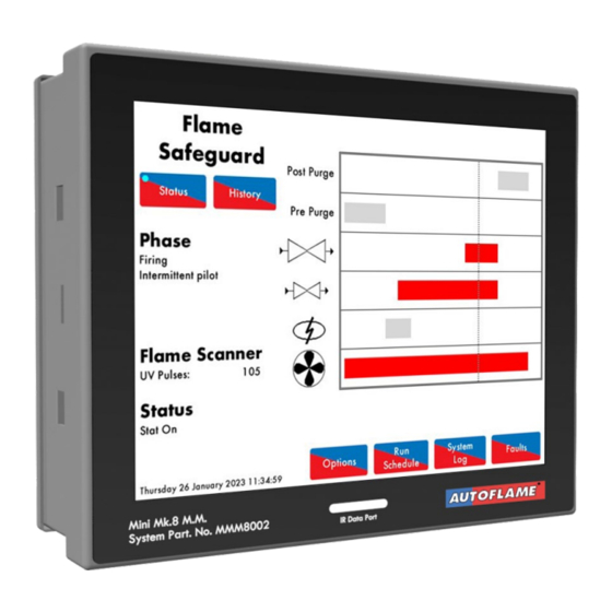
Operation OPERATION 6.1. Home Screen Figure 6.1.i Home The home screen shown in Figure 6.1.i. displays the Flame Safeguard screen. The Flame Safeguard screen displays the following information: Current phase of the MM • Flame scanner signal strength • Throughout the entire firing sequence, the vertical dotted line will move horizontally showing the currently active components. -
Page 61: Flame Safeguard - History
Operation 6.1.1. Flame Safeguard – History Figure 6.1.1.i Flame Safeguard – History Press in the Flame Safeguard screen (Figure 6.1.i) to view Flame Safeguard History screen in Figure 6.1.1.i. The flame scanner signal and firing rate histories are displayed. This data is logged for 24 hours on the unit. -
Page 62: Options
Operation 6.1.2. Options Figure 6.1.2.i Options Press in the main screen (6.1.i) to view Options screen in Figure 6.1.2.i. The Options screens display all the options and their settings, however no changes can be made to these settings. To make changes to the Options, please refer to section 2. -
Page 63: Parameters
Operation 6.1.3. Parameters Figure 6.1.3.i Parameters Press tab in the Option screen (Figure 6.1.2.i) to view the Parameters screen in Figure 6.1.3.i. The Parameters screens display all the parameters and their settings. To make changes to these Parameters, refer to section 2. Flame Safeguard Manual Page | 63... -
Page 64: Run Times
(Figure 6.1.i) to view the Run Times screen in Figure 6.1.4.i. You will be prompted to enter a password. Run Times sets when the Autoflame Flame Safeguard unit is scheduled to be on and firing or off. - Page 65 Operation Figure 6.1.4.ii Run Times – ON Press in the Run Times screen (Figure 6.1.4.ii) to enable the Run Times (set to and have the Flame Safeguard controller determine when the burner may fire. Press in the Run Times screen (Figure 6.1.4.ii) to disable (set to ) the run times allowing the burner to fire whenever the external control demands.
- Page 66 Operation Figure 6.1.4.iii Run Times – Monday To set the schedule, press on the bar for that day in the Run Times On/Off screen (Figure 6.1.4.ii) to bring up the individual day editing screen (Figure 6.1.4.iii). Drag the at the 00:00 time to add new intervals, and drag them to the required time position. Up to 4 time periods can be set.
-
Page 67: System Log
Operation 6.1.5. System Log Figure 6.1.5.i System Log Press in the Commission Mode screen or Flame Safeguard Home screen (Figure 2.1.ii or 6.1.i) to view the System Log screen as shown in Figure 6.1.5.i. This data is stored on the MM and the SD card for 1000 entries. -
Page 68: Faults
Operation 6.1.6. Faults Figure 6.1.6.i Faults Press in the Home screen (Figure 6.1.i) to view the burner Lockouts, Errors, Alarms and Warnings (Figure 6.1.6.i). The MM will store up to 64 burner Lockouts and MM errors. Flame Safeguard Manual Page | 68... -
Page 69: Burner Start-Up Sequence
If any errors or lockouts occur, please contact Autoflame Engineering Ltd or your local Autoflame Technology Centre. The following start-up sequence is shown for an example burner application. The system has been set up with these burner control features: •... -
Page 70: Recycle
Burner Start-Up Sequence 7.1. Recycle Figure 7.1.i Recycle When the burner enters the Recycle phase shown in Figure 7.1.i, both the fuel valves and air damper go to their respective commissioned ‘closed’ positions, and the burner is not firing. As the burner is off in Recycle, there should not be any flame detected. The UV scanner checks that there is no flame, and if a flame is detected, the lockout ‘Simulated Flame’... -
Page 71: Standby
Burner Start-Up Sequence 7.2. Standby Figure 7.2.i Standby The burner will go into Standby shown in Figure 7.2.i., before the safety checks begin to initiate the burner start-up sequence. The Flame Safeguard controller will remain in this phase if it is waiting due to the Run Schedule being active, but the current phase being OFF. -
Page 72: Internal Relay Tests
Burner Start-Up Sequence 7.3. Internal Relay Tests Figure 7.3.i Relay Test 1 During the Internal Relay Tests phase shown in Figure 7.3.i., the MM will check its internal flame safe relays 1 to 5. Should any Lockouts occur now for the relay tests such as ‘FSR Test 1A’ this is an indication of an internal fault within the MM. -
Page 73: Cpi Input
Burner Start-Up Sequence 7.4. CPI Input Figure 7.4.i CPI Input In the Wait CPI phase shown in Figure 7.4.i, a check is made on terminal 55 for the proof of closure switch. If terminal 55 does not see an input within 5 seconds, the lockout ‘No CPI Reset’ will occur. Flame Safeguard Manual Page | 73... -
Page 74: Valve Proving
Burner Start-Up Sequence 7.5. Valve Proving Figure 7.5.i VPS Venting In this example, the Flame Safeguard controller has no vent valve and has single valve pilot optioned. 2 Valve proving is used to check the integrity of the gas for any leaks. See option/parameter 130. During the VPS Venting phase shown in Figure 7.5.i., the main gas valve 1 is checked. - Page 75 Burner Start-Up Sequence Figure 7.5.ii VPS Air Proving In the VPS Air Proving phase shown in Figure 7.5.ii, the main gas valve 2 output is off (closed) and the main gas valve 1 output is off (closed), to check for a pressure increase. After the valves close, there is a 1.5 second delay after which the air pressure switch must remain off.
- Page 76 Burner Start-Up Sequence Figure 7.5.iii VPS Void to Gas In the VPS Void to Gas phase shown in Figure 7.5.iii, the main gas valve 1 output is on (open), and the main gas valve 2 is output off (closed) – gas is let through to fill the void. If no voltage is detected when the burner main gas valve 1 output T60 should be on (and vice versa), the lockout ‘Main Gas 1 Output Fault’...
- Page 77 Burner Start-Up Sequence Figure 7.5.iv VPS Gas Proving In the VPS Gas Proving phase shown in Figure 7.5.iv, the outputs of main gas valves 1 and 2 are both off (closed), to check for any gas leaks in the void between the main valves. After the valves close, there is 1.5 second delay after which the gas pressure switch must be on, indicating the pressure is above the set value.
-
Page 78: Wait For Air Switch
Burner Start-Up Sequence 7.6. Wait for Air Switch Figure 7.6.i Zero Air Sensor Once the VPS checks are competed, if an air switch is used on T54, the Flame Safeguard controller will go to the Wait for Air Switch phase. If a reset of voltage is not seen and the MM is in this phase more than 2 minutes, the lockout ‘Wait Air Switch Timeout’... -
Page 79: Purge
Burner Start-Up Sequence 7.7. Purge Figure 7.7.i Run to Purge Once all the internal relay and VPS checks have been made, the motor moves to their purge positions in the Run to Purge phase shown in Figure 7.7.i. The burner motor output is switched on. If no voltage is detected when the burner motor output T58 should be on (and vice versa), the lockout ‘Motor Output Fault’... - Page 80 Burner Start-Up Sequence Figure 7.7.ii Purge No Air Switch The Purge No Air Switch phase shown in Figure 7.7.ii allows a delay before the air switch is checked. See option/parameter 121. Note: A purge position interlock must be connected to terminal 81; this input must be made in order for the system to begin the purge phase, see option/parameter 155.
- Page 81 Burner Start-Up Sequence Figure 7.7.iii Purge Air Switch Once the ‘delay from start of the purge before the air switch is checked’ has elapsed, if using an air switch, line voltage must be present on T54 throughout the purge cycle and maintained until the burner enters the Recycle phase on Shut Down.
-
Page 82: Ignition
Burner Start-Up Sequence 7.8. Ignition Figure 7.8.i Run to Ignition In the Run to Ignition phase shown in Figure 7.8.i, the motor will move to the start position. A start position interlock is connected to terminal 80; This input must be made to initiate the ignition phase. In the On/Off burner setup, The T70 (switched neutral) turning off can be used to swap the drive from T81 to T80 (Start Switch) through the relay to initiate the ignition phase. - Page 83 Burner Start-Up Sequence Figure 7.8.ii Pre-ignition The ignition transformer output is switched on in the Pre-ignition phase shown in Figure 7.8.ii, before the pilot gas valve is switched on (open). See option/parameter 113. If no voltage is detected when the ignition output T63 should be on (and vice versa), the lockout ‘Ignition Output Fault’...
-
Page 84: Pilot
Burner Start-Up Sequence 7.9. Pilot Figure 7.9.i Pilot Open The pilot gas valve is switched on (open) in the Pilot Open phase shown in Figure 7.9.i. The 1 safety time is the period when the pilot valve is open before the flame is checked. See option/parameter 114. If no voltage is detected when the pilot valve output T59 should be on (and vice versa), the fault ‘Start Gas Output Fault’... - Page 85 Burner Start-Up Sequence Figure 7.9.ii Ignition At the end of the 1 safety time period, the pilot flame is checked by the UV scanner in the Single Valve Pilot Ignition shown in Figure 7.9.ii. If the pilot goes out, the lockout ‘No Flame Signal’ will occur. Flame Safeguard Manual Page | 85...
- Page 86 Burner Start-Up Sequence Figure 7.9.iii Pilot Proving The ignition transformer output is switched off after the pilot ignition, in the Pilot Proving phase shown in Figure 7.9.iii. This proving period gives the pilot flame a chance to stabilise. The flame is checked to ensure the pilot is strong.
-
Page 87: Proving
Burner Start-Up Sequence 7.10. Proving Figure 7.10.i Main Flame Prove Second Safety Time The 2 safety time begins, where the flame is checked in the Interrupted Pilot 2 Safety phase shown in Figure 7.10.i. The 2 safety time is the period where the pilot/main valves overlap. The outputs of the main gas valves 1 and 2 are switched on (opened), while the pilot valve output is maintained on (opened). - Page 88 Burner Start-Up Sequence Figure 7.10.ii Main Flame Prove In the Interrupted Pilot Main Valve Prove phase shown in Figure 7.10.ii, the pilot gas valve output is switched off (closed). There is a time delay to allow the main flame to stabilise before the burner proceeds to normal modulation as set.
-
Page 89: Firing
Burner Start-Up Sequence 7.11. Firing Figure 7.11.i Firing The burner has now completed the start-up sequence. T71 Release to modulate is activated to switch control of the servo motor to the load sensor and the burner fires normally and modulates according to this load sensor. The Flame Safeguard controller remains in the Firing phase shown in Figure 7.11.i until the signal on T53 is removed, indicating a shutdown of the burner, or a flame detection error is seen. -
Page 90: Post Purge
Burner Start-Up Sequence 7.12. Post Purge Figure 7.12.i Post Purge The Post-Purge phase is shown in Figure 7.12.i. When T53 is switched off to turn the burner off, the Flame Safeguard controller will close the fuel valves and take back control of the servo. If a post purge is set, it will drive the servo to open, purging fresh air through the burner/boiler, when the burner shuts down in normal conditions. -
Page 91: Unlocking The Autoflame Flame Safeguard Unit Toa Mini Mk8
A Mini Mk8, set to operate in Flame Safeguard Mode only, can be purchased under Order Code MMM8002/FSG and comes pre-locked. If you want to unlock a Flame Safeguard unit, to work as a fully functional Mini Mk8, you will need to go into commission mode, and then press the Unlock button. - Page 92 Unlocking the Autoflame Flame Safeguard to Mini Mk8 MM Figure 8.1.ii After pressing the Unlock button, you can upload the unlock code via Download Manager or Enter code. Once the unlock button has been pressed, you have the option of using Download Manager and an IR Lead to upload the unlock code.
-
Page 93: Errors And Lockouts
Check for noise on the mains input, wiring and voltages on all terminals • EEPROM Error Fault communicating with the on board EEPROM Contact Autoflame approved local Tech Centre • ADC Error Internal fault Contact Autoflame approved local Tech Centre •... - Page 94 Errors and Lockouts Error Message Description Watchdog Timeout Internal fault Contact Autoflame approved local Tech Centre • Processor Clock Error Internal fault • Contact Autoflame approved local Tech Centre System Error Internal fault • Contact Autoflame approved local Tech Centre...
- Page 95 Errors and Lockouts Error Message Description Gas Pressure Run Commission Commissioned gas pressure during Golden/ FGR start or Fault main curve is below option/ parameter 136 threshold Check option/ parameter 136 and check gas pressure. • • Re-commission gas pressure sensor Air Pressure Commission Fault Commissioned air pressure during Golden/ FGR start or main curve is too low...
-
Page 96: Lockouts
Errors and Lockouts 9.2. Lockouts Lockouts occur when the Flame Safeguard controller detects a fault with the burner operation such as VPS, gas/air pressure sensor and flame scanners. The lockout must be cleared and investigated on the Flame Safeguard controller. Only a subset of Lockouts will be relevant when in flame safeguard mode. Other Lockouts are greyed out in the table below. - Page 97 • Check option/parameters 136 and 138 • VPS Pressure Zeroing Gas pressure sensor cannot be zeroed at VPS venting Check gas pressure is within zero range (see Autoflame Sensors Guide) • • Check vent valve Freeze Timeout MM kept in Phase Hold for more than 10minutes •...
- Page 98 Wrong gas pressure sensor detected • Check option/parameters 128 and 156 Gas Sensor Fault Internal pressure sensor fault • Contact Autoflame approved local tech centre UV Pot Fault Hardware fault • Contact Autoflame approved local tech centre Air Sensor Comms Signal lost from air pressure sensor •...
- Page 99 MM status after lockout has been reset (Modbus) • Power up CPU Test Fail Internal check failed Contact Autoflame approved local tech centre • Power up EEPROM Test Fail Internal check failed • Contact Autoflame approved local tech centre Flame Safeguard Manual Page | 99...
-
Page 100: Alarms And Warnings
Errors and Lockouts 9.3. Alarms and Warnings Alarms and warnings are faults detected with the system operation. If an alarm occurs, the burner will stop running, and if a warning occurs, the burner will continue to run. The following options/parameters set whether system operation faults are set as alarms or warnings: Option 13 EGA Fault Response... - Page 101 Errors and Lockouts Fault Message Description Exhaust Temperature Upper Exhaust temperature is above upper limit offset of Limit commissioned value* • Alarm or warning depending on option 13. Check exhaust gas readings and parameter 96. • Exhaust Temperature Exhaust temperature is above absolute limit* Absolute Limit Alarm or warning depending on option 13.
-
Page 102: Setting Conflicts
Errors and Lockouts 9.4. Setting Conflicts Some of the option/parameter values may require another option/parameter to be set, as described in the table below. The Flame Safeguard controller will be forced into Commission Mode. Only a subset of these will be relevant when in flame safeguard mode, however no options may be set in conflict without causing an Options/Parameters lockout and must be cleared. - Page 103 Errors and Lockouts Setting Conflict Message (118) (141) (149) Purge air pres. threshold cannot be higher when post purge is optioned • If post purge is enabled, then the purge air pressure threshold cannot be set higher than the running air pressure threshold.
-
Page 104: Forced Commission
Errors and Lockouts 9.5. Forced Commission The Flame Safeguard controller will be forced into Commission mode if there is a setting conflict and/or one or more of the following conditions occurs (This list is a subset of the forced commission for an unlocked Mini Mk8 MM): Forced Commission Message BC Option/parameter mismatch. - Page 105 AUTOFLAME FLAME SAFEGUARD CONTROLLER MANUAL MMM8002/FSG 20 JAN 2023 Autoflame Engineering LTD Unit 1-2, Concorde Business Centre Airport Industrial Estate, Wireless Road Biggin Hill, Kent TN16 3YN United Kingdom Tel: +44 (0)1959 578 820 Email: technicalsupport@autoflame.com Website: www.autoflame.com...
Need help?
Do you have a question about the MMM8002/FSG and is the answer not in the manual?
Questions and answers