AUTOFLAME Mk8 MM End User Manual
Hide thumbs
Also See for Mk8 MM:
- Manual (395 pages) ,
- Installation and commissioning manual (170 pages) ,
- Installation & commissioning manual (118 pages)
Table of Contents
Advertisement
Quick Links
Advertisement
Table of Contents

Related Manuals for AUTOFLAME Mk8 MM


Summary of Contents for AUTOFLAME Mk8 MM
- Page 1 Mk8 MM End User Guide...
- Page 2 Department: This manual and all the information contained herein is copyright of Autoflame Engineering Ltd. It may not be copied in the whole or part without the consent of the Managing Director. Autoflame Engineering Ltd’s policy is one of continuous improvement in both design and manufacture.
- Page 3 Autoflame product range, i.e. combustion, electrical and control. The sale of Autoflame’s systems and equipment referred to in this Manual assume that the dealer, purchaser and installer has the necessary skills at his disposal. i.e. A high...
-
Page 4: Table Of Contents
Contents OVERVIEW AND BENEFITS……………………………………………………………………………… 1 Features and Benefits…………………………………………………………………………………………… 1 System Example…………………………………………………………………………………………………… 4 Micro-Modulation (MM)………………………………………………………………………………………. 5 ELECTRICAL SPECIFICATIONS………………………………………………………………………….. 6 Classifications………………………………………………………………………………………………………. 6 Inputs and Outputs………………………………………………………………………………………………. 6 Cable Specifications……………………………………………………………………………………………… 8 END USER OPERATION…………………………………………………………………………………… 9 Home Screen…………………………………………………………………………………………………… 9 3.1.1 Home Screen Components……………………………………………………………………… 10 3.1.2 Faults………………………………………………………………………………………………………... - Page 5 Gas Pressure Sensor Screen 35 3.6.1 Gas Pressure…………………………………………. 25 3.6.2 Gas Sensor – History………………………………………………………………………………. 26 Air Pressure Sensor Screen……………………………………………………………………………. 27 3.7.1 Air Pressure……………………………………………………………………………………………. 27 3.7.2 Air Sensor – History………………………………………………………………………………… 28 First Outs………………………………………………………………………………………………………..29 System Configuration Screen…………………………………………………………………………. 30 3.9.1 Language Selection…………………………………………………………………………………. 31 3.9.2 Options……………………………………………………………………………………………………32 3.9.3...
-
Page 6: Overview And Benefits
Fully metered combustion control for commissioning based on equivalence ratio and excess air Draft control to maintain stack pressure Password protection of all safety related functions Infra-red port for upload/download of commission data 22.05.2017 Mk8 MM End User Guide Page 1... - Page 7 DTI will collect operational data for up to 10 MM modules, 10 EGA modules and 10 universal I/O modules in one communications loop Information transmitted via RS422 or Ethernet link to local PC/network for running Autoflame CEMS Audit software...
- Page 8 Detailed logging inputs and outputs when coupled with Mk7 DTI 16 Line voltage inputs (110V/ 230V) 6 Analogue inputs and 6 analogue outputs 8 Volt free contacts Configurable alarms through Mk7 DTTI 22.05.2017 Mk8 MM End User Guide Page 3...
-
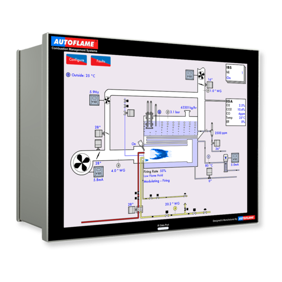
Page 9: System Example
1 Overview and Benefits System Example Page 4 Mk8 MM End User Guide 22.05.2017... -
Page 10: Micro-Modulation (Mm)
The Micro-Modulation module is the basic building block of the Autoflame System. The Autoflame MM module provides an easily programmable and flexible means of optimising combustion quality throughout the load requirement range of the burner/boiler unit whilst ensuring the temperature is accurate to within 1°C (°F) and pressure to within 1 PSI (0.1Bar). -
Page 11: Electrical Specifications
0.6 power factor 0.6 power factor 0.6 power factor Max Load 6A 0.6 power factor 0.6 power factor 100mA To drive relay only – switched neutral 100mA To drive relay/lamp only – switched neutral Page 6 22.05.2017 Mk8 MM End User Guide... - Page 12 4. Low voltage cables should be screened cable as specified in section 2.3. 5. The burner ‘High Limit Stat’ must be a manual reset type. Note: There is a lid (back plate) fitted onto the back of the Mk8 MM with a Warning label to prevent any unauthorised fuse replacements.
-
Page 13: Cable Specifications
STC OS1P24 Samples are available upon request. Low voltage and data cable can be ordered directly from Autoflame Engineering, please contact Autoflame Sales. When using a VSD, please review the manufacturer’s guidelines on installations to prevent EMC including the recommendations for reactors and filters. -
Page 14: End User Operation
This boiler room setup can be configured to display what is actually on site, please see section 3.19.5 Boiler Room Configuration. 22.05.2017 Mk8 MM End User Guide Page 9... -
Page 15: Home Screen Components
Oil flowing No oil flowing Combustion Induced air fan draught fan Gas flame Oil flame Capacitance probes conductivity probe External level Steam sensor for header water level TDS probe Feed water pump Page 10 Mk8 MM End User Guide 22.05.2017... - Page 16 3 End User Operation Information Three Pass Fire Tube Page 11 22.05.2017 Mk8 MM End User Guide...
-
Page 17: Faults
Reset button or input on T56 Error Internal or hardware fault Power cycle Alarm Critical system fault Reset button or input Warning Non-critical fault Reset button First out Configurable fault Optional Reset button/ auto Page 12 Mk8 MM End User Guide 22.05.2017... -
Page 18: Status Screen
(option 15), the DTI is controlling the setpoint (option 16), external setpoint is enabled (parameter 72), or OTC is enabled (option 80). Note: Use parameters 29 and 30 to adjust the load detector reading if required. Page 13 22.05.2017 Mk8 MM End User Guide... -
Page 19: Status - History
This information is logged for 2 years on the DTI when connected with the MM. Note: Power cycling the MM or changing fuel will reset the 24 hour history data log on the MM. Page 14 Mk8 MM End User Guide 22.05.2017... -
Page 20: Status - Burner Enable/Disable
Figure 3.2.3.i Status – Burner Enable/Disable Press and hold for 3 seconds in the Status screen in Figure 3.2.1.i to disable the burner. Press and hold this same button to enable the burner. Page 15 22.05.2017 Mk8 MM End User Guide... -
Page 21: Status - Low Flame Hold
Press and hold this button again to return to normal modulation. Alternatively, the Mk8 MM can also be put in low flame hold via an input on terminal 95. If low flame hold or hand mode is selected on the MM screen, this will override an input made on terminal 94 or 95. -
Page 22: Status - Hand Mode
Note: If low flame hold and hand mode are both selected, then hand mode takes priority. Note: If a firing rate limit is set (option 66), then the firing cannot be driven past this in hand mode. Page 17 22.05.2017 Mk8 MM End User Guide... -
Page 23: Fuel-Air Screen
Figure 3.3.1.i Fuel-Air – Curve Press the flame in the Home screen in Figure 3.1.i to view the Fuel-Air screen, which shows current servomotor and VSD output positions, the trim status and the commission curve graph. Page 18 Mk8 MM End User Guide 22.05.2017... -
Page 24: Fuel-Air - Map
Note: Option 12 must be set to 2 or 3 for the 3-parameter trim function to be activated. Page 19 22.05.2017 Mk8 MM End User Guide... -
Page 25: Fuel-Air - History
This information is logged for 2 years on the DTI when connected with the MM. Note: Power cycling the MM or changing fuel will reset the 24 hour history data log on the MM. Page 20 Mk8 MM End User Guide 22.05.2017... -
Page 26: Flame Safeguard Screen
Note: If a flame switch is used for flame detection, then flame switch show as either on (flame detected) or off (no flame detected). Please refer to section XX for the start-up sequence of the burner. Page 21 22.05.2017 Mk8 MM End User Guide... -
Page 27: Flame Safeguard - History
This information is logged for 2 years on the DTI when connected with the MM. Note: Power cycling the MM or changing fuel will reset the 24 hour history data log on the MM. Page 22 Mk8 MM End User Guide 22.05.2017... -
Page 28: Channels Screen
This information is logged for 2 years on the DTI when connected with the MM. Note: Power cycling the MM or changing fuel will reset the 24 hour history data log on the MM. Page 23 22.05.2017 Mk8 MM End User Guide... -
Page 29: Vsd Channel
This information is logged for 2 years on the DTI when connected with the MM. Note: Power cycling the MM or changing fuel will reset the 24 hour history data log on the MM. Page 24 Mk8 MM End User Guide 22.05.2017... -
Page 30: Gas Pressure Sensor Screen 35 3.6.1 Gas Pressure
Commissioned gas pressure for the corresponding point on fuel-air curve Actual (current) gas pressure Valve proving gas pressure Status of main gas and vent valves Upper/lower offset gas pressure limits for fuel-air curve Page 25 22.05.2017 Mk8 MM End User Guide... -
Page 31: Gas Sensor - History
This information is logged for 2 years on the DTI when connected with the MM. Note: Power cycling the MM or changing fuel will reset the 24 hour history data log on the MM. Page 26 Mk8 MM End User Guide 22.05.2017... -
Page 32: Air Pressure Sensor Screen
If commissioned with an EGA, the air pressure is stored during the commissioning the trim function, and shown as the red line on the graph. Page 27 22.05.2017 Mk8 MM End User Guide... -
Page 33: Air Sensor - History
This information is logged for 2 years on the DTI when connected with the MM. Note: Power cycling the MM or changing fuel will reset the 24 hour history data log on the MM. Page 28 Mk8 MM End User Guide 22.05.2017... -
Page 34: First Outs
Burner stops firing and restarts automatically when the input state changes. Stop EGA Sampling Burner continues firing, but the EGA stops sampling. Stops EGA Trimming Burner continues firing, but the EGA trim stops operating. Page 29 22.05.2017 Mk8 MM End User Guide... -
Page 35: System Configuration Screen
View system log In the top left corner, the serial number and bootloader of the MM are shown, and in the top righ, the BC, MM and Display software versions are shown. Page 30 22.05.2017 Mk8 MM End User Guide... -
Page 36: Language Selection
Autoflame tech centre for this password. Note: The SD card must contain the language file to be able to select the language. If a language required is not available, please contact the Autoflame office. Page 31 Mk8 MM End User Guide... -
Page 37: Options
Options highlighted in blue are ones which have been changed from the default values. Press on the MM, PID, EGA, DTI and BC tabs to group together options in those categories. Page 32 22.05.2017 Mk8 MM End User Guide... -
Page 38: Parameters
Parameters highlighted in blue are ones which have been changed from the default values. Press on the MM, PID, EGA, DTI and BC tabs to group together parameters in those categories. Page 33 Mk8 MM End User Guide 22.05.2017... -
Page 39: Expansion Options
Expansion options highlighted in blue are ones which have been changed from the default values. Press on the MM, PID, EGA, DTI and BC tabs to group together expansion options in those categories. Page 34 22.05.2017 Mk8 MM End User Guide... -
Page 40: Set Clock
Note: If the MM is connected to a DTI, then then time and data will be set by the DTI and cannot be adjusted on the MM. Page 35 Mk8 MM End User Guide 22.05.2017... -
Page 41: Manual
System Configuration screen in Figure 3.19.i to view the Manual screen. Press on the section headings to navigate through the operating manual. Note: The SD card must contact the manual file to be able to view the operating manual on the MM screen. Page 36 22.05.2017 Mk8 MM End User Guide... -
Page 42: Commission Data
3 End User Operation 3.9.7 Commission Data Figure 3.19.11.i Commission Data Press in the System Configuration screen in Figure 3.19.i to view the Commission Data screen. Page 37 Mk8 MM End User Guide 22.05.2017... -
Page 43: Diagnostics
This data is logged hourly on the SD card for up to 3 months. The minimum and maximum values are the lowest and highest values the MM as detected for this measurement. Page 38 22.05.2017 Mk8 MM End User Guide... -
Page 44: System Log
System Configuration screen in Figure 3.19.i to view the System Log screen, which stores 1000 entries of the following information: Stat on/ off Setting changes Commission/single point change Fuel flow commission MM restart Setpoint changes Page 39 Mk8 MM End User Guide 22.05.2017... -
Page 45: Errors And Lockouts
Channel 1 Movement Error Servomotor moves when not expected and vice versa Check wiring and voltages on terminals 70 – 77 Check servomotors drive in correct direction and valve is not stuck Page 40 22.05.2017 Mk8 MM End User Guide... - Page 46 Check for noise on the mains input, wiring and voltages on all terminals EEPROM Error Fault communicating with the on board EEPROM Contact Autoflame approved local tech centre ADC Error Internal fault Contact Autoflame approved local tech centre...
- Page 47 Missing Commissioning Data Internal fault Check there is commissioning data for all options servomotors/VSD FAR Execution Speed Internal fault Contact Autoflame approved local Tech Centre Software Error Internal fault Contact Autoflame approved local Tech Centre Software Error Internal fault ...
- Page 48 Internal fault Contact Autoflame approved local Tech Centre ADC Reference Voltage Error Hardware fault Contac Contact Autoflame approved local Tech Centre Contact Autoflame approved local Tech Centre Software error Internal fault Contact Autoflame approved local Tech Centre...
-
Page 49: Lockouts
Call a certified Commissioning Engineer to investigate Shutter Fault UV signal detected during shutter operation on self-check Check wiring on terminals 21 and 22 Check UV scanner type and check option/ parameter 110 is set accordingly Page 44 22.05.2017 Mk8 MM End User Guide... - Page 50 Check gas pressure Check option/ parameter 137 RAM Test Failed Hardware fault Contact Autoflame approved local tech centre PROM Test Failed Hardware fault Contact Autoflame approved local tech centre FSR Test 1A Internal relay test failed ...
- Page 51 Terminal 85/86 Fault Hardware fault on terminals 85/86 Check wiring and voltages on terminals 85, 86 and contact Autoflame Proving Circuit Fail T52 Loss of input on terminal 52; MM must see input at all times from position to purge to post purge ...
- Page 52 Signal lost from gas pressure sensor Check wiring and screen on terminals 31 – 34 Gas Sensor Type Internal fault Contact Autoflame approved local tech centre Gas Sensor Fault Internal pressure sensor fault Contact Autoflame approved local tech centre UV Pot Fault Internal UV scanner fault ...
- Page 53 Input has been made before the blower starts; it should only be made continuously during purge. Check wiring on terminal 81. BC Input Short Internal fault Contact Autoflame approved local tech centre Lockout 199 Internal fault Contact Autoflame approved local tech centre Lockout Cleared Lockout has been cleared ...
-
Page 54: Alarms And Warnings
Check exhaust gas readings and option 27 NO Upper Limit NO value is above upper limit offset of commissioned value* Alarm or warning depending on option 13 Check exhaust gas readings and parameter 94 Page 49 Mk8 MM End User Guide 22.05.2017... - Page 55 Wave signature high to low peak distance is less than still Detected water threshold Alarm Check still water threshold in expansion option 28 Check capacitance probe 1 reading history Page 50 22.05.2017 Mk8 MM End User Guide...
- Page 56 Check water level readings for probes and sensor if optioned Re-commission probes/sensor Permanent Alarm Reset Input Input held on alarm reset terminal for more than 10 seconds Alarm Check input on terminal M/R Page 51 Mk8 MM End User Guide 22.05.2017...
- Page 57 Check wiring and screen on terminals 5T+, 5T-, 4P- and 4P+ Second Low Probe Hardware Internal check failed Fault Alarm Contact Autoflame approved local tech centre Permanent Test Input Input held on test terminal for more than 60 seconds Alarm Check input on terminal TST...
- Page 58 Check wiring and screen on terminals 5T+ and 5T- Bottom Blowdown Controller Internal check failed Software Fault Warning Contact Autoflame approved local tech centre Bottom Blowdown Servo No movement detected when bottom blowdown valve goes Closing Fault to close Warning ...
- Page 59 Main power has failed on bottom blowdown controller Main Power Fault Warning Contact Autoflame approved local tech centre Bottom Blowdown Servo Not Bottom blowdown controller has not been requested to drive Commissioned servomotor to closed since it was powered on ...
- Page 60 Check wiring and screen on terminals – and T2 Air Temp Sensor Fault (T3) Fault or no comms with T3 sensor Warning (MM will use commissioned temperature) Check wiring and screen on terminals – and T3 Page 55 Mk8 MM End User Guide 22.05.2017...
- Page 61 A combustion limit error will occur if the current exhaust value has crossed the combustion limit for the number of trim cycles set in parameter 17 (the default value is 3 cycles). Page 56 22.05.2017 Mk8 MM End User Guide...
-
Page 62: Settings Conflicts
Check options 43 and 57. (43) (135) NFPA Post Purge cannot be optioned with multi-burner The multi-burner function can only use standard, not NFA post purge. Check option 43 and option/parameter 135. Page 57 Mk8 MM End User Guide 22.05.2017... - Page 63 Check option/parameters 125, 126, 127, 128, 129 and 135. (P85) (16) Modulation exerciser cannot be used with sequencing. Modulation exerciser should be used for test purposes and cannot be used with sequencing. Check option 16 and parameter 85. Page 58 22.05.2017 Mk8 MM End User Guide...
- Page 64 (E62) (E120) Bottom blowdown reduction requires steam flow to be enabled. If bottom blowdown reduction is enabled, then steam flow metering must be enabled. Check expansion options 62 and 120. Page 59 Mk8 MM End User Guide 22.05.2017...
- Page 65 (E140) (152, E156) Fully metered requires gas fuel 3 to have non-zero density. Density must be set for gas in fully metered control. Check option 152 and expansion options 150 and 156. Page 60 22.05.2017 Mk8 MM End User Guide...
- Page 66 (E81) (E129) Servo channel 7 via I/O unit cannot be optioned with heat flow sensors via I/O unit. Heat flow sensors from the I/O unit cannot be optioned with servo channel via I/O unit. Check expansion options 81 and 129. Page 61 Mk8 MM End User Guide 22.05.2017...
-
Page 67: Forced Commission Reasons
Air pressure at one or more commissioned points is less than option/parameters 147 and/or 149. IR Upload was completed successfully, check configuration then restart. Check data has uploaded successfully before restarting in run mode. Page 62 22.05.2017 Mk8 MM End User Guide... - Page 68 Fully metered control has been enabled but not commissioned. Fully metered configuration does not match commissioning. One or more sensors used for fully metered control that were not present during commissioning are now enabled. Page 63 Mk8 MM End User Guide 22.05.2017...
-
Page 69: Troubleshooting And Further Information
This can cause internal damage to the MM Snubbers can be used on these old gas valves to protect the MM from these spikes; they should be fitted across the power terminals of the gas valves. Please contact Autoflame Sales for more information. -
Page 70: Channel Positioning Error
This will cause an Input Fault lockout to occur. If this lockout persists, the mains input should be checked. To troubleshoot this issue, please check for any DC voltage in the mains voltage and contact your local power supplier. Page 65 Mk8 MM End User Guide 22.05.2017... -
Page 71: Standards
Standards STANDARDS The Mk8 MM has been tested and approved to the following standards: UL 372, 5 Edition C22.2 No. 199 – M89 BS EN 298:2012 BS EN 12067-2:2004 BS EN 1643:2014 BS EN 1854 ISO 23522:2007 AS 4625 – 2008 AS 4630 –... - Page 72 Autoflame Engineering Ltd Unit1-2 Concorde Business Centre Airport Industrial Estate, Wireless Road Biggin Hill, Kent TN16 3YN United Kingdom +44 (0) 845 872 2000 www.autoflame.com...
Need help?
Do you have a question about the Mk8 MM and is the answer not in the manual?
Questions and answers