AUTOFLAME MK8 Manual
Hide thumbs
Also See for MK8:
- Installation & commissioning manual (118 pages) ,
- Installation and commissioning manual (125 pages)

Related Manuals for AUTOFLAME MK8


Summary of Contents for AUTOFLAME MK8
- Page 1 Combustion Management Systems AUTOFLAME MK8 FLAME SAFEGUARD CONTROLLER MANUAL MM80001/FSG 08 FEB 2024...
- Page 2 MM80001/FSG 08 FEB 2024 This manual and all the information contained herein is copyright of Autoflame Engineering Ltd. It may not be copied in the whole or part without the consent of the Managing Director. Autoflame Engineering Ltd’s policy is one of continuous improvement in both design and manufacture. We therefore reserve the right to amend specifications and/or data without prior notice.
- Page 3 The sale of Autoflame’s systems and equipment referred to in this Manual assume that the dealer, purchaser and installer has the necessary skills at his disposal. i.e. A high degree of combustion engineering experience, and a thorough understanding of the local electrical codes of practice concerning boilers, burners and their ancillary systems and equipment.
-
Page 4: Table Of Contents
Expansion Board Terminals Description ..................28 Relay Box............................... 29 1.5.1 Relay Box Terminal Description ....................29 Converting a Flame Safeguard unit to an Autoflame Flame Safeguard ..........31 1.6.1 Converting Honeywell Flame Safeguard Units ................31 1.6.2 Converting Fireye Flame Safeguard Units ..................33 Standards............................... - Page 5 Proving ..............................127 9.11 Firing ..............................128 9.12 Post Purge ............................129 UNLOCKING THE AUTOFLAME FLAME SAFEGUARD UNIT TO A MK8 MM ........130 10.1 Fully Unlocking the Autoflame Flame Safeguard Controller ..............130 ERRORS AND LOCKOUTS ........................133 11.1 Errors ..............................
- Page 6 VERY IMPORTANT SAFETY NOTES Please fully read and understand the following notes before commencing with any work related to the Mk8 MM Flame Safeguard Controller. Failing to do so can result in serious injury or even death, and can cause serious equipment and substantial property damage.
-
Page 7: Autoflame Flame Safeguard Overview, Specifications And Wiring
12.1” multi-touch screen interface. MODBUS (MK8006) connectivity & First Outs (MK8007) requires unlock codes to use these features. With the Mk8 MM, it is possible to control all boiler processes from a single 12.1” multi-touch screen interface without any added module. -
Page 8: Autoflame Flame Safeguard Main Features
Internal flame safeguard – full flame supervision with self-check UV, IR & Flame switch. • Dual flame scanner operation (IR and UV scanners) • Gas valve train leak supervision via Autoflame gas pressure sensor as a low gas pressure limit • Air pressure proving and monitoring via Air switch •... -
Page 9: Fixing Holes And Dimensions
Autoflame Flame Safeguard Overview, Specifications and Wiring 1.1.2 Fixing Holes and Dimensions Flame Safeguard (MM80001/FSG) Manual Page | 15... -
Page 10: Installation
This digital apparatus does not exceed the Class B limits for radio noise of digital apparatus set out in the Radio Interference Regulations of the Canadian Department of Communications. 1.2.1. Humidity The Autoflame Flame Safeguard controller is designed to operate in a maximum 90 percent relative humidity, continuous, noncondensing moisture environment. Condensing moisture can cause a shutdown. 1.2.2. -
Page 11: Environmental Classification
Autoflame Flame Safeguard Overview, Specifications and Wiring 1.2.4. Environmental Classification The Flame Safeguard Controller meets the following climate specification: Climate: Min. Temperature 0°C (32°F) Recommended Temperature Less than 40°C (104°F) Max. Temperature 60°C (140°F) Humidity 0 to 90% non-condensing Storage: Temperature -20 to 85°C (-4 to 185°F) -
Page 12: Wiring
Autoflame Flame Safeguard Overview, Specifications and Wiring 1.3 Wiring 1. For the internal block diagram of the Autoflame Flame Safeguard controller, see section 1.3.1, 1.3.2 & 1.3.3. 2. Disconnect the power supply before beginning installation to prevent electrical shock and equipment damage. -
Page 13: Servo Motor Control Schematic Main Board
Autoflame Flame Safeguard Overview, Specifications and Wiring 1.3.1 Servo Motor Control Schematic Main Board IF IN DOUBT ASK AUTOFLAME TECHNICAL DEPARTMENT LOW VOLTAGE 500mA 500mA ALL LOW VOLTAGE WIRING TO THE CONTROL IS TO BE WIRED AS PART OF A CLASS 1 CIRCUIT... -
Page 14: On/Off Burner Control Schematic
Autoflame Flame Safeguard Overview, Specifications and Wiring 1.3.2 On/Off Burner Control Schematic IF IN DOUBT ASK AUTOFLAME TECHNICAL DEPARTMENT LOW VOLTAGE 500mA 500mA ALL LOW VOLTAGE WIRING TO THE CONTROL IS TO BE WIRED AS PART OF A CLASS 1 CIRCUIT... -
Page 15: Expansion Board
Autoflame Flame Safeguard Overview, Specifications and Wiring 1.3.3 Expansion Board ALL LOW VOLTAGE WIRING TO THE CONTROL IS TO BE WIRED AS PART OF A CLASS 1 CIRCUIT 1-12 FIRST OUT ANNUNCIATION LINE VOLTAGE INPUTS. LABELS AND OPERATION, SETUP ON MM... -
Page 16: Fuse Ratings
Autoflame Flame Safeguard Overview, Specifications and Wiring 1.3.4 Fuse Ratings Fu s e Ratin g Spare P art Nu m ber 6.3A (T) FU10026 Fuse 1 protects the mains input to the MM, including the mains output terminals 50 – 64. -
Page 17: Electrical Specifications
The burner ‘High Limit Stat’ must be a manual reset type. • All external safety devices that require manual reset must be reset external to the Autoflame system and prior to completing the recycling interlock. The cover (back plate) of the Flame Safeguard controller must always be re-fitted after the wiring is completed to prevent access to the electric shock hazard areas, unauthorised wiring modifications or fuse replacement. -
Page 18: Expansion Board Inputs And Outputs
Autoflame Flame Safeguard Overview, Specifications and Wiring 1.4.5 Expansion Board Inputs and Outputs Outputs: 120/230 V All outputs with the exception of PF are switched neutrals 100mA (alarm indicator on MM board) Maximum 2A (load currents for above terminal) Main Voltage Signal Inputs: At 120V current loading is approximately maximum 0.7mA per input. -
Page 19: Cable Specifications
Belden 9502 for 4-core shielded cable (2 twisted pairs) • STC OS1P24 Samples are available upon request. Low voltage and data cable can be ordered directly from Autoflame Engineering, please contact Autoflame Sales. Flame Safeguard (MM80001/FSG) Manual Page | 25... -
Page 20: Terminals Description
29, 30 Digital communications connections to an Autoflame IR scanner 31, 32 Digital communications connections to an Autoflame gas pressure sensor 0V supply to an Autoflame gas pressure sensor +12V supply to an Autoflame gas pressure sensor 0V supply to an Autoflame IR scanner... - Page 21 Note that outputs T70 and T71 are switched neutrals and must be connected to the motor through relays. Autoflame provide the relay box (SP80070, SP80070/110) to facilitate this. Alternatively, relays may be wired in as per the wiring schematic in section 1.3.1.
-
Page 22: Expansion Board Terminals Description
Autoflame Flame Safeguard Overview, Specifications and Wiring 1.4.8 Expansion Board Terminals Description All terminals marked S are internally connected. They are provided for connections to the various screened cables. First Out annunciation line voltage input 1 First Out annunciation line voltage input 2... -
Page 23: Relay Box
Autoflame Flame Safeguard Overview, Specifications and Wiring 1.5 Relay Box The relay box (SP80070, SP80070/110) provides all the connections shown in section 1.3.1 for wiring between a servo motor with high and low limit switches and the Flame Safeguard controller. It also provides for the switchover of control to a load sensor allowing the burner to modulate once the flame has been established. - Page 24 Autoflame Flame Safeguard Overview, Specifications and Wiring For an On/Off burner, connections are defined in section 1.3.2 for an On-delay timer relay to allow the start-up sequence to be carried out. CAUTION - Equipment Damage Hazard. Improper connection or replacement of relays or the relay box will cause equipment failure.
-
Page 25: Converting A Flame Safeguard Unit To An Autoflame Flame Safeguard
Autoflame Flame Safeguard Overview, Specifications and Wiring 1.6 Converting a Flame Safeguard unit to an Autoflame Flame Safeguard The tables below list the connections on other flame safeguard devices and the corresponding Autoflame terminal to be used in an upgrade. - Page 26 Output SHUTTER Notes 1: Any flame sensing device will need to be replaced with an Autoflame sensor. For more details, please see the Autoflame Flame scanner guide. 2: Switched neutral output should be connected to neutral side of relay coil.
-
Page 27: Converting Fireye Flame Safeguard Units
PRE-IGNITION INTERLOCKS (FUEL VALVE END SWITCH) Notes 1: Any flame sensing device will need to be replaced with an Autoflame sensor. For more details, please see the Autoflame Flame scanner guide. 2: The pilot configuration may vary for Terminals W, 5 & 6. Check which connects to the ignition transformer. -
Page 28: Standards
Options & Parameters 1.7 Standards The Autoflame Flame Safeguard unit has been tested and approved to the following standards: • BS EN 298: 2012 • BS EN 1643: 2014 • BS EN 1854: 2010 • BS EN 12067-2: 2004 •... -
Page 29: Options And Parameters
The Options, Parameters and Expansion Options must only be changed by factory trained and certified technicians who have a thorough appreciation of the Autoflame combustion systems and the combustion process in general. Any person changing these settings without the correct factory training and understanding of the boiler plant may place themselves and others in a potentially dangerous situation. - Page 30 Options & Parameters Figure 2.1.ii Enter Commissioning Password “Enter Commissioning Password” is displayed. Use the keypad to enter the password, then press . Press to change the value of an incorrect entry. Note: The commissioning password should not be distributed to anyone who is not a factory trained and a certified engineer.
- Page 31 View fault logs, system log and diagnostics Note: Commissions may only be carried out with a fully unlocked Mk8 MM. The number of commissions will remain at zero unless the unit has been fully unlocked at any time and will not increment while in flame safeguard mode.
- Page 32 PLEASE NOTE: Although all Options/Parameters are settable, the majority only apply to a fully unlocked MK8 MM (MM80001) - details of how to unlock the Flame Safeguard controller to a Mk8 MM is provided in section 8. Options and parameters which have no impact when set as a Flame Safeguard unit have been greyed out in the tables below.
- Page 33 Return to curve at purge speed. Return to curve at modulating speed. MM: Flame Safeguard Mode Once Enabled the MK8 MM, operates as a simple Flame Safeguard. Option/parameter 154 (T80) Start Position Interlock & option/parameter 155 (T81) Purge Position Interlock must be used.
- Page 34 Options & Parameters Opt. # Default Range Description MM: Servomotor Channels Channel 1 is always enabled for fuel; this option sets the channels in use. Channels 1 & 2 Channels 1, 2 & 3 Channels 1, 2, 3 & 4 Note: If option 8 is changed after commissioning, then the MM will need to be re-commissioned, unless this option is returned to its previous setting.
- Page 35 Options & Parameters Opt. # Default Range Description EGA: EGA Fault Response EGA faults generate Alarms (burner stops) EGA faults generate Warnings (burners runs) Note: EGA alarms will drive the common system alarm output (terminal 79), see option 14 for warning response. MM: Warning Response Warnings do not drive Common System Alarm output (terminal 79) Warnings drive Common System Alarm output (terminal 79)
- Page 36 Options & Parameters Opt. # Default Range Description EGA: O Lower Limit Offset If the current O value is below this offset limit from the commissioned value, an alarm/warning (see option 13) will occur, with option 12 set to 3. Disabled 1 –...
- Page 37 Options & Parameters Opt. # Default Range Description DTI: Maximum Remote Setpoint (DTI/ Modbus/External) If a required value command is received from the DTI or Modbus that is above this maximum remote setpoint value, then it will be ignored by the MM.
- Page 38 Options & Parameters Opt. # Default Range Description DTI: Warming Facility for Low Pressure Steam For sequencing applications where non-return valves are not installed, it is not possible to use a setpoint to keep the boilers in a standby condition. A thermostat (aquastat) can be installed into the boiler’s shell.
- Page 39 Options & Parameters Opt. # Default Range Description MM: Cold Start Inhibit Time If the MM progresses from low fire cold start to firing and the burner shuts down within this cold start inhibit time, a cold start will not occur when the burner starts up again.
- Page 40 Options & Parameters Opt. # Default Range Description DTI: Steam Sequencing Burner Off Time When the MM is in warming mode, it will warm to the standby setpoint according to the on and off times set in options 53 and 54. Disabled 1 –...
- Page 41 Options & Parameters Opt. # Default Range Description 3725 MM: Fuel 1 Calorific Value This is the gross calorific value/higher heating value (HHV) including the latent heat of vaporisation of water. To set either metric or imperial units, see parameter 40. If the units are changed, then this option must be changed accordingly.
- Page 42 Options & Parameters Opt. # Default Range Description MM: Continuous Pilot Shut Off Threshold If continuous pilot is enabled (see option/parameter 111), then if the actual value is higher than the combined burner switch-off offset (option 10) and this offset above the required setpoint in continuous pilot firing, the burner will go off.
- Page 43 F, PSI or 0.1 bar or 0.01 bar for low pressure sensor (depends on load detector set in option 1 and metric/imperial units set in parameter 40) MM: Channel 1 Servo Control Method Autoflame Servo Motor, 0.1 degree control Autoflame Servo Motor, 0.5 degree control Industrial Servo Motor, 0.1 degree control Industrial Servo Motor, 0.5 degree control...
- Page 44 Options & Parameters Opt. # Default Range Description MM: Input Signal to MM from VSD Channel 5 Input range 4 to 20mA Input range 0 to 20mA Input range 0 to 10V MM: Input Units Displayed, VSD Channel 5 Selected input signal Hertz MM: Input Low Speed to MM from VSD Channel 5 0 –...
- Page 45 Options & Parameters Opt. # Default Range Description VSD Channel 6 Feedback Fault Tolerance This is used to check that the feedback varies while modulating. For example, if this option is set to 4%, the tolerance that is allowed while firing is ±4% of the whole VSD range.
- Page 46 Options & Parameters Opt. # Default Range Description BC: UV Flame Scanner Type See option/parameter 120 for the UV threshold and 122 for the flame sensor operation. For setting 2, the self-check UV scanner opens and closes a shutter to check that the UV scanner is not giving a false flame signal. Standard scanner Self-check scanner BC: Pilot Type...
- Page 47 Options & Parameters Opt. # Default Range Description BC: Post-Purge Time If set, a post-purge will occur after a normal burner shutdown. This time set should allow for the servomotors to travel from low fire to purge position. The flame is not checked during post-purge. See option/parameter 135 for NFPA post-purge.
- Page 48 BC: Fuel Pressure Sensor Mode – Fuel 1 Gas: For setting 1, valve proving and pressure limits are checked by an Autoflame gas sensor. For setting 2, low pressure limit can be checked by external pressure switch. For setting 3, the system will wait for a mains voltage input on terminal 55 to confirm that the VPS test is completed.
- Page 49 Options & Parameters Opt. # Default Range Description BC: VPS Operation VPS operates before start-up VPS operates after shutdown VPS operates before and after BC: Gas Valve Configuration No vent valve Vent normally closed Vent normally open No vent valve. Single valve pilot Vent normally closed.
- Page 50 This is the minimum air pressure that must be detected by the MM during purge, when using an Autoflame air pressure sensor. If this is set to 0, then MM will look for the minimum air pressure set in option/ parameter 149.
- Page 51 This is the minimum air pressure that must be detected by the MM during normal firing and during purge when option/ parameter 141 is set to 0, when using an Autoflame air pressure sensor. See parameter 43 for air pressure display units.
- Page 52 Options & Parameters Opt. # Default Range Description BC: Fuel 3 Type BC: Fuel 4 Type BC: Terminal T80 Function Setting 1 allows an additional safety check on the valves and damper to ensure that they are in the correct position for start/low fire. See Valves and Servomotors manual for information on setup and wiring.
-
Page 53: Parameters
Options & Parameters 2.2 Parameters Figure 2.2.i Commission Mode – Parameters Press in the Commission Mode screen to access the Parameters. Any number of options/ parameters can be changed at one time. By pressing MM, PID, EGA, DTI or BC at the bottom of the screen, the options/ parameters can be grouped together by feature. - Page 54 EGA: EGA Version Mk7 - For use with Mk7 EGA Mk8 Protocol (Legacy) – For use with Mk8 EGA Mk8 Protocol (RS485) – For use with Mk8 EGA EVO Unused EGA: CO Used for Trim on Oil If the fuel has been set as oil (see options/ parameters 150 to 153), then the trim function can include CO to calculate the required trim correction.
- Page 55 CO appears fuel rich, then the air damper will open further to remove CO. Disabled Enabled EGA: (Mk7 Only) Air Calibration Time For the Mk8 EGA, this is set as default 6 minutes. 20 – 300 Seconds Unused Trim Samples per Cycle A cycle is the period between when does the EGA carries out a drain to get rid of excess moisture in the exhaust gas sample.
- Page 56 Value 1000 = 100.0% of actual reading MM: Load Sensor Filter Time 1 – 40 Seconds EGA: (Mk7 Only) Efficiency Calculation Method For the Mk8 EGA, efficiency calculation method is set on the EGA itself. English European MM: User Setpoint Minimum Value 0 - 9990 This limits the change for the minimum setpoint value in the status screen.
- Page 57 This sets the highest MM ID number for that sequence or DTI loop. 1 –10 Sequence ID EGA: Air Calibration on Startup For the Mk8 EGA, the air calibration schedule is set on the EGA itself. Disabled Enabled Unused MM: Logo Display Timer (Standby) If a custom logo is stored on the data SD card in the MM, then after this timer in standby mode, the custom logo will appear on the screen.
- Page 58 Options & Parameters Par.# Default Range Description MM: Backlight On Time If the screen is not pressed and this timer elapses, the backlight will dim. Disabled 1 – 1800 Seconds DTI: Hot Water Sequencing For setting 0 the boilers, the lag boilers will be off. For setting 1, the lag boiler will operate as steam sequencing, as set in option 41.
- Page 59 Enabled MM: Bluetooth Module Enables/disables the on-board Bluetooth module for the purpose of connectivity with the Autoflame Download Manager software. See Autoflame PC Software Guide. To enable connectivity via the IR port, this option must be disabled, Bluetooth and IR cannot be used at the same time.
- Page 60 Options & Parameters Par.# Default Range Description MM: Stat Exerciser Period If the stat exerciser period is enabled, then T53 will be turned off for this timer set, and then turned off for this timer set, repeatedly. This should be used in test/inspection conditions.
- Page 61 Options & Parameters Par.# Default Range Description MM: Assured Low Fire Shut Off If enabled, when the burner turns off on internal stat, the MM will modulate to low fire, shut down and recycle the system before turning off. Assured low fire shut off cannot be used with graceful shutdown in parameter 99.
- Page 62 Options & Parameters Par.# Default Range Description MM: Software Voltage Conditioner The MM performs internal tests to ensure that the mains power is safe for the unit to operate (zero crossing and mains input tests). When these tests return a negative result the MM generates a fault. This parameter governs the way the MM handle these tests results;...
-
Page 63: Language
Press in the System Configuration screen in Figure 2.3.i to access Language Selection screen; you will be prompted to enter the Online Changes password. Please contact your local approved Autoflame tech centre for this password. Note: The SD card must contain the language file to be able to select the language. If a language required is not available, please contact the Autoflame office. -
Page 64: Set Clock
Options & Parameters 2.4 Set Clock Figure 2.4.i Set Clock Press in the System Configuration screen in Figure 2.4.i to access the Set Clock screen; you will be prompted to enter the password (10, 10). Change the time and data using the arrows then press and then press Flame Safeguard (MM80001/FSG) Manual... -
Page 65: Configuring The Autoflame Flame Safeguard Unit
Make certain that: 1. The wiring connections are correct and all terminal screws are tight. 2. The flame detector(s) is clean, installed and correctly positioned. Consult the Autoflame Flame Scanner guide for instructions. 3. The burner is completely installed and ready to fire; consult equipment manufacturer instructions. -
Page 66: Single Servo Burner Set Up
The wiring is to be completed as shown in the schematic in section 1.2.1. The Relay Box (SP80070, SP80070/110) is available from Autoflame to provide all the correct connections for ease of installation. If using other relays, ensure that you conform to the wiring schematic provided. -
Page 67: Installation Checks
The reliability of the equipment may be impaired if used in environments where strong electromagnetic fields exist e.g. if the equipment is installed in a boiler house where radio systems exist then additional EMC (Electro Magnetic Compatibility) measures may have to be considered. Please contact Autoflame for more information. 3.2.4 Maintenance and Servicing The Micro-Modulation unit uses solid state technology. -
Page 68: General Features
General Features 4 GENERAL FEATURES 4.1 No Pre-Purge It is possible to minimise the burner start-up time by bypassing the pre-purge. The major advantage of this control means that the overall boiler efficiency is increased by minimising the heat loss to the stack during a purge cycle. This means the burner starts-up quicker therefore reaching setpoint in a reduced time. -
Page 69: Autoflame Flame Safeguard Flame Detection Using Flame Switch
General Features 4.2 Autoflame Flame Safeguard Flame Detection Using Flame Switch The Mk8 MM can utilise an external flame switch for the purpose of flame detection. To configure operation with a flame switch, option/parameter 122 can be set to 1. -
Page 70: Terminals 80 And 81 Functions
Please check Autoflame Valves Guide for further details. When set up as an On/Off burner this is a live input after the completion of the purge sequence to initiate the start-up process. -
Page 71: Valve Proving With Autoflame Gas Sensor
4.4 Valve Proving with Autoflame Gas Sensor There’s an option to use a Autoflame Gas Sensor, for valve proving. This is enabled using option 125/126/127/128 by selecting “1”, Pressure Limits, Valve Proving. The Gas Pressure sensor doesn’t require for it to be commissioned, when used for Flame Safeguard mode. -
Page 72: Expansion Features
Commission Mode screen. Direct Modbus & First Outs are the only Expansion features, that can be used for the Autoflame Flame Safeguard unit. For details on other unlock codes, please check the specific expansion feature’s section for the relevant expansion options in the Mk8 MM manual. -
Page 73: Direct Modbus
Through a Mk8 DTI connected to the Mk8 MM. If Direct Modbus is used on the Mk8 MM (for example connecting the MM directly to a Building Management System - BMS), then neither Autoflame Intelligent Boiler Sequencing (IBS) nor the DTI can be used on that MM. -
Page 74: Direct Modbus Expansion Options
Expansion Features 6.2 Direct Modbus Expansion Options The table below shows the Expansion Options used for configuring Direct Modbus. Default Range Description Modbus: Sequencing/DTI or Modbus Function If Direct Modbus is enabled, then option 16 must be set to 0, as Intelligent Boiler Sequencing cannot be used with direct Modbus. -
Page 75: Setup And Configuration
Up to 10 MMs can be linked together and connected to any Management System that supports Modbus protocol via terminals 27 and 28. Each Mk8 MM needs to be set with an individual Modbus Device ID in expansion option 104. -
Page 76: Modbus Addresses
Expansion Features 6.4 Modbus Addresses There are 4 types of Modbus addresses: 0x Read/Write Digital outputs – off/on commands These are binary values and have a 0/1 value indicating an off/on or no/yes value. 1x Read Digital inputs – off/on signals/indications These are multiple integer values and can 3x Read Analogue inputs –... - Page 77 Expansion Features Type Description Details 12001 Water Level Optioned 0 = Water level not optioned 1 = Water level optioned 12002 Units Imperial or Metric 0 = Imperial 1 = Metric 12003 Feedwater Pump State 0 = Pump off 1 = Pump on 12004 TDS Units 0 = ppm...
- Page 78 Expansion Features Type Description Details 12022 First Out 1 Not Reset 0 = No First Out 1 Errors, 1= First Out 1 needs to be Reset 12023 First Out 2 Not Reset 0 = No First Out 2 Errors, 1= First Out 2 needs to be Reset 12024 First Out 3 Not Reset 0 = No First Out 3 Errors,...
- Page 79 Expansion Features Type Description Details 30101 Load Index Firing rate % 30102 Firing Status 0 = Non-modulating 1 = Modulating Returns value 0 single point change, fuel flow metering and commissioning *For Setting 1 see section 6.4.1 30104 Burner Rating MW x 10 Metric units determined from fuel flow metering 30105...
- Page 80 Expansion Features Type Description Details 30132 Current Flow Thousands Metric kW Imperial MMBTU/hr x 1000 Remainder after whole number of MW or MMBTU/hr x 1000 taken away. E.g. 1.5MW gives 500 value and 15.1MMBTU/hr gives 100 value 30133 Current Flow Millions Metric MW Imperial MMBTU/hr Whole number of MW or MMBTU/hr.
- Page 81 Expansion Features Type Description Details 30149 Flame Switch Status 0 = Off 1 = On 30150 EGA Current NO Value ppm x 10 30151 ppm x 10 EGA Commissioned NO Value 30801 Fuel 4 Flow Total Thousands Metric kW/hr Imperial MMBTU/hr Remainder after whole number of MW/hr or MMBTU x 1000 taken away, x 1000.
- Page 82 Expansion Features Type Description Details 32005 Capacitance Probe 2 Signal Hz reading 32006 Capacitance Probe 2 Reading Metric: mm on MM Imperial: inches x 10 32009 Alarm Status 0 = No alarm 1 = Alarm 32010 Warning Status 0 = No warning 1 = Warning 32012 Alarm Code...
- Page 83 Expansion Features Type Description Details 32053 Auxiliary High Water Input 0 = Input not active 1 = input active 32054 Auxiliary 1 Low Input 0 = Input not active 1 = input active 32055 Auxiliary 2 Low Input 0 = Input not active 1 = input active 32056 Combined Water level Reading...
- Page 84 Remote Firing Rate Percentage (%) 40131 must be set to 1 to change the firing rate remotely 40131 Remote Firing Rate Enable 0 = Remote firing rate disabled 1 = remote firing rate enabled Mk8 MM Manual Page | 90...
-
Page 85: Modbus Address For Mm Status (30102)
Main Flame Proving Golden Start Firing Moving to low fire to shut down Moving to low fire for COF Changeover COF Changeover Firing on Continuous Pilot Only Run to Post-Purge Post-Purge Post-Firing Valve Proving Fault Mk8 MM Manual Page | 91... -
Page 86: First Outs
If first outs are enabled, they can be configured and labelled in Commission mode and Online Changes. To tie the first outs interlock to the MM’s safety stat, see option / parameter 145. Disabled Enabled Mk8 MM Manual Page | 92... -
Page 87: First Outs Configuration
First Outs 7.3 First Outs Configuration 7.3.1 Enabling First Outs To enable first outs, the following expansion must be set. Expansion Option Description Setting First Outs function 7.3.2 Accessing First Outs First Outs can only be configured in Commission mode. Press in commission mode or press in Flame Safeguard mode to access the First outs screens. -
Page 88: First Out Function
First Outs 7.3.3 First Out Function In the First Outs screen, press on the First Out number to be configured and select the function of first out when upon the active state set for high or low. Function When Active Description Disabled Does not function. -
Page 89: Edit First Out Label
First Outs 7.3.4 Edit First Out Label On the Configure First Out screen, press the First Out label highlighted in blue under Touch Label to Edit, use the on-screen keyboard to edit the name as required, once finished press to save the change. Figure 7.3.4 Editing First Out Label Page | 95 Flame Safeguard (MM80001/FSG) Manual... -
Page 90: First Outs Interlock
First Outs 7.3.5 First Outs Interlock The First Outs can be directly and automatically connected to the stat circuit on the Autoflame Flame safeguard unit without the need to physically connect the First Outs to terminal 53 on the MM. - Page 91 First Outs The schematic below shows an example of wiring First Outs on a Autoflame Flame Safeguard unit. Figure 7.3.5 ii First Outs Wiring Diagram Page | 97 Flame Safeguard (MM80001/FSG) Manual...
-
Page 92: Operation
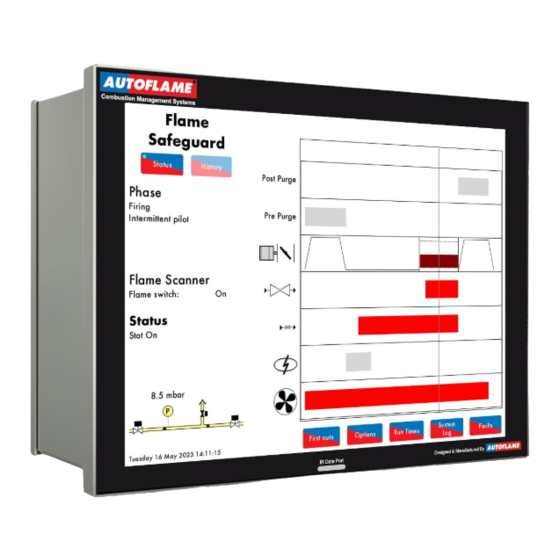
Operation 8 OPERATION 8.1 Home Screen Figure 8.1.i Home The home screen shown in Figure 8.1.i. displays the Flame Safeguard screen. The Flame Safeguard screen displays the following information: • Current phase of the MM • Flame scanner signal strength (UV, IR) or Flame detected (Flame Switch) •... -
Page 93: Flame Safeguard - History
Operation 8.1.1 Flame Safeguard - History Figure 8.1.1.i Flame Safeguard – History Press in the Flame Safeguard screen (Figure 8.1.i) to view Flame Safeguard History screen in Figure 8.1.1.i (History screen won’t be accessible if using a Flame Switch). The flame scanner signal history is displayed. This data is logged for 24 hours on the unit. -
Page 94: Options
Operation 8.1.2 Options Figure 8.1.2.i Options Press in the main screen (8.1.i) to view Options screen in Figure 8.1.2.i. The Options screens display all the options and their settings, however no changes can be made to these settings. To make changes to the Options, please refer to section 2. -
Page 95: Parameters
Operation 8.1.3 Parameters Figure 8.1.3.i Parameters Press tab in the Option screen (Figure 8.1.2.i) to view the Parameters screen in Figure 8.1.3.i. The Parameters screens display all the parameters and their settings. To make changes to these Parameters, refer to section 2. -
Page 96: Expansion
Operation 8.1.4 Expansion Figure 8.1.4.i Expansion Press tab in the Option screen (Figure 8.1.2.i) to view the Expansion screen in Figure 8.1.4.i. The Expansion screens display all the Expansion options and their settings. To make changes to these Expansion options, refer to section 2. Flame Safeguard (MM80001/FSG) Manual Page | 102... -
Page 97: Run Times
(Figure 8.1.i) to access the Run Times screen in Figure 8.1.5.i. You will be prompted to enter a password (11, 11). Run times sets when the Autoflame Flame Safeguard unit is scheduled to be on and firing or off. - Page 98 Operation Figure 8.1.5.ii Run Times – Enabled Press in the Run Time screen in Figure 8.1.5.i to enable Run Times. Press on the bar next to the day to set the run times for that day of the week. To disable the run times press Flame Safeguard (MM80001/FSG) Manual Page | 104...
- Page 99 Operation Figure 8.1.5.iii Run Times - Friday To set the schedule, press on the bar for that day in the Run Times On/Off screen (Figure 8.1.5.ii) to bring up the individual day editing screen (Figure 8.1.5.iii). Drag the at the 00:00 time to add new intervals, and drag them to the required time position. Up to 4 time periods can be set.
-
Page 100: System Log
Operation 8.1.6 System Log Figure 8.1.6.i System Log Press in the Commission Mode screen or Flame Safeguard Home screen (Figure 2.1.ii or 8.1.i) to view the System Log screen as shown in Figure 8.1.6.i. This data is stored on the MM and the SD card for 1000 entries. -
Page 101: First Outs
Operation 8.1.7 First Outs Figure 8.1.7.i First Outs screen First outs can be used in Flame Safeguard mode, but MK8007 must be unlocked. If this is locked/disabled, then the button won’t appear on the main screen as shown on figure 8.1.i. You can view the First outs screen, by pressing button. -
Page 102: Faults
Operation 8.1.8 Faults Press in the Home screen (Figure 8.1.i) to view the burner Lockouts, Errors, Alarms and Warnings (Figure 8.1.8.i). The MM will store up to 64 burner Lockouts and MM errors. Fault Type Shuts Down Burner Reset By Lockout Burner control fault Reset button or input on T56... -
Page 103: Burner Start-Up Sequence
If any errors or lockouts occur, please contact Autoflame Engineering Ltd or your local Autoflame Technology Centre. The following start-up sequence is shown for an example burner application. The system has been set up with these burner control features: •... -
Page 104: Recycle
Burner Start-Up Sequence 9.1 Recycle Figure 9.1.i Recycle When the burner enters the Recycle phase shown in Figure 9.1.i, both the fuel valves and air damper go to their respective commissioned ‘closed’ positions, and the burner is not firing. As the burner is off in Recycle, there should not be any flame detected. The UV scanner checks that there is no flame, and if a flame is detected, the lockout ‘Simulated Flame’... -
Page 105: Standby
Burner Start-Up Sequence 9.2 Standby Figure 9.2.i Standby The burner will go into Standby shown in Figure 9.2.i., before the safety checks begin to initiate the burner start-up sequence. The Flame Safeguard controller will remain in this phase if it is waiting due to the Run Schedule being active, but the current phase being OFF. -
Page 106: Internal Relay Tests
Burner Start-Up Sequence 9.3 Internal Relay Tests Figure 9.3.i Relay Test 1 During the Internal Relay Tests phase shown in Figure 9.3.i., the MM will check its internal flame safe relays 1 to 5. Should any Lockouts occur now for the relay tests such as ‘FSR Test 1A’ this is an indication of an internal fault within the MM. -
Page 107: Cpi Input
Burner Start-Up Sequence 9.4 CPI Input Figure 9.4.i CPI Input In the Wait CPI phase shown in Figure 9.4.i, a check is made on terminal 55 for the proof of closure switch. If terminal 55 does not see an input within 5 seconds, the lockout ‘No CPI Reset’ will occur. Flame Safeguard (MM80001/FSG) Manual Page | 113... -
Page 108: Valve Proving
Burner Start-Up Sequence 9.5 Valve Proving Figure 9.5.i VPS Venting In this example, the Flame Safeguard controller has no vent valve and has single valve pilot optioned. 2 Valve proving is used to check the integrity of the gas for any leaks. See option/parameter 130. During the VPS Venting phase shown in Figure 9.5.i., the main gas valve 1 is checked. - Page 109 Burner Start-Up Sequence Figure 9.5.ii VPS Air Proving In the VPS Air Proving phase shown in Figure 9.5.ii, the main gas valve 2 output is off (closed) and the main gas valve 1 output is off (closed), to check for a pressure increase. After the valves close, there is a 1.5 second delay after which the air pressure switch must remain off.
- Page 110 Burner Start-Up Sequence Figure 9.5.iii VPS Void to Gas In the VPS Void to Gas phase shown in Figure 9.5.iii, the main gas valve 1 output is on (open), and the main gas valve 2 is output off (closed) – gas is let through to fill the void. If the measured static line pressure is below the offset lower limit set in option/parameter 138, then a ‘gas pressure low limit’...
- Page 111 Burner Start-Up Sequence Figure 9.5.iv VPS Gas Proving In the VPS Gas Proving phase shown in Figure 9.5.iv, the outputs of main gas valves 1 and 2 are both off (closed), to check for any gas leaks in the void between the main valves. After the valves close, there is 1.5 second delay before the initial gas pressure reading is taken.
-
Page 112: Wait For Air Switch
Burner Start-Up Sequence 9.6 Wait for Air Switch Figure 9.6.i Zero Air Sensor Once the VPS checks are competed, if an air switch is used on T54, the Flame Safeguard controller will go to the Wait for Air Switch phase. If a reset of voltage is not seen and the MM is in this phase more than 2 minutes, the lockout ‘Wait Air Switch Timeout’... -
Page 113: Purge
Burner Start-Up Sequence 9.7 Purge Figure 9.7.i Run to Purge Once all the internal relay and VPS checks have been made, the motor moves to their purge positions in the Run to Purge phase shown in Figure 9.7.i. The burner motor output is switched on. If no voltage is detected when the burner motor output T58 should be on (and vice versa), the lockout ‘Motor Output Fault’... - Page 114 Burner Start-Up Sequence Figure 9.7.ii Purge No Air Switch The Purge No Air Switch phase shown in Figure 9.7.ii allows a delay before the air switch is checked. See option/parameter 121. Note: A purge position interlock must be connected to terminal 81; this input must be made in order for the system to begin the purge phase, see option/parameter 155.
- Page 115 Burner Start-Up Sequence Figure 9.7.iii Purge Air Switch Once the ‘delay from start of the purge before the air switch is checked’ has elapsed, if using an air switch, line voltage must be present on T54 throughout the purge cycle and maintained until the burner enters the Recycle phase on Shut Down.
-
Page 116: Ignition
Burner Start-Up Sequence 9.8 Ignition Figure 9.8.i Run to Ignition In the Run to Ignition phase shown in Figure 9.8.i, the motor will move to the start position. A start position interlock is connected to terminal 80; This input must be made to initiate the ignition phase. In the On/Off burner setup, The T70 (switched neutral) turning off can be used to swap the drive from T81 to T80 (Start Switch) through the relay to initiate the ignition phase. - Page 117 Burner Start-Up Sequence Figure 9.8.ii Pre-ignition The ignition transformer output is switched on in the Pre-ignition phase shown in Figure 7.8.ii, before the pilot gas valve is switched on (open). See option/parameter 113. If no voltage is detected when the ignition output T63 should be on (and vice versa), the lockout ‘Ignition Output Fault’...
-
Page 118: Pilot
Burner Start-Up Sequence 9.9 Pilot Figure 9.9.i Pilot 1 Safety The pilot gas valve is switched on (open) in the Pilot Open phase shown in Figure 9.9.i. The 1 safety time is the period when the pilot valve is open before the flame is checked. See option/parameter 114. If no voltage is detected when the pilot valve output T59 should be on (and vice versa), the fault ‘Start Gas Output Fault’... - Page 119 Burner Start-Up Sequence Figure 9.9.ii Pilot Ignition At the end of the 1 safety time period, the pilot flame is checked by the UV scanner in the Single Valve Pilot Ignition shown in Figure 7.9.ii. If the pilot goes out, the lockout ‘No Flame Signal’ will occur. Flame Safeguard (MM80001/FSG) Manual Page | 125...
- Page 120 Burner Start-Up Sequence Figure 9.9.iii Pilot Proving The ignition transformer output is switched off after the pilot ignition, in the Pilot Proving phase shown in Figure 9.9.iii. This proving period gives the pilot flame a chance to stabilise. The flame is checked to ensure the pilot is strong. If the pilot goes out, the lockout ‘No Flame Signal’...
-
Page 121: Proving
Burner Start-Up Sequence 9.10 Proving Figure 9.10.i Main Flame Proving The 2 safety time begins, where the flame is checked in the Intermittent Pilot 2 Safety phase shown in Figure 7.10.i. The 2 safety time is the period where the pilot/main valves overlap. The outputs of the main gas valves 1 and 2 are switched on (opened), while the pilot valve output is maintained on (opened). -
Page 122: Firing
Burner Start-Up Sequence 9.11 Firing Figure 9.11.i Firing The burner has now completed the start-up sequence. T71 Release to modulate is activated to switch control of the servo motor to the load sensor and the burner fires normally and modulates according to this load sensor. The Flame Safeguard controller remains in the Firing phase shown in Figure 9.11.i until the signal on T53 is removed, indicating a shutdown of the burner, or a flame detection error is seen. -
Page 123: Post Purge
Burner Start-Up Sequence 9.12 Post Purge Figure 9.12.i Post Purge The Post-Purge phase is shown in Figure 9.12.i. When T53 is switched off to turn the burner off, the Flame Safeguard controller will close the fuel valves and take back control of the servo. If a post purge is set, it will drive the servo to open, purging fresh air through the burner/boiler, when the burner shuts down in normal conditions. -
Page 124: Unlocking The Autoflame Flame Safeguard Unit To A Mk8 Mm
A Mk8 MM, set to operate in Flame Safeguard Mode only, can be purchased under Order Code MM80001/FSG and comes pre-locked. If you want to unlock a Flame Safeguard unit, to work as a fully functional Mk8 MM, you will need to go into commission mode, and then press the Expansion features button. - Page 125 Lead to upload the unlock code. Figure 10.1.iii If you don’t haven an IR Lead, then you can enter the code via the MK8 MM Alternatively, by pressing the “Enter Code” button, you can type in the Unlock code on the keypad, if you don’t have access to the Download Manager Software.
- Page 126 Figure 10.1.iv Flame Safeguard has been unlocked, allowing Flame Safeguard unit to be a MK8 MM Once unlocked, the Flame Safeguard mode can be turned on/off by accessing Option 4. Figure 10.1.v Flame Safeguard mode can be disabled, allowing the Flame Safeguard unit to be a MK8 MM Flame Safeguard (MM80001/FSG) Manual...
-
Page 127: Errors And Lockouts
Errors & Lockouts 11 ERRORS AND LOCKOUTS 11.1 Errors Errors occur when the Flame Safeguard controller detects an internal fault, component out of range, internal check failure or power supply issue. To clear an error, the Flame Safeguard controller must be restarted. Error Message Description... - Page 128 Check for noise on the mains input, wiring and voltages on all terminals EEPROM Error Fault communicating with the on board EEPROM • Contact Autoflame approved local tech centre ADC Error Internal fault • Contact Autoflame approved local tech centre...
- Page 129 Errors & Lockouts Error Message Description FAR Execution Speed Internal fault • Contact Autoflame approved local Tech Centre Software Error Internal fault • Contact Autoflame approved local Tech Centre Software Error Internal fault • Contact Autoflame approved local Tech Centre...
- Page 130 Commissioned air zero pressure is more than 5mbar from sensor’s zero value • Check air pressure sensor value during VPS Software error Internal fault • Contact Autoflame approved local Tech Centre Software error Internal fault • Contact Autoflame approved local Tech Centre Software error Internal fault •...
-
Page 131: Lockouts
Errors & Lockouts Lockouts 11.2 Lockouts occur when the MM detects a fault with the burner operation such as VPS, gas/air pressure sensor and flame scanners. The lockout must be cleared and investigated on the MM. Lockout Message Description CPI Input Wrong State Proof of closure switch opened during ignition sequence •... - Page 132 Check option/parameter 136 VPS Air Zeroing Gas pressure sensor cannot be zeroed at VPS venting • Check gas pressure is within zero range (see Autoflame Sensors Guide) • Check vent valve Oil Pressure Too Low Oil pressure below offset lower limit during running •...
- Page 133 Terminal 85/86 Fault Hardware fault on terminals 85/86 • Check wiring and voltages on terminals 85, 86 and contact Autoflame Proving Circuit Fail T52 Loss of input on terminal 52; MM must see input at all times from position to purge to post-purge •...
- Page 134 Signal lost from gas pressure sensor • Check wiring and screen on terminals 31 – 34 Gas Sensor Type Internal fault • Contact Autoflame approved local tech centre Gas Sensor Fault Internal pressure sensor fault • Contact Autoflame approved local tech centre UV Pot Fault Internal UV scanner fault •...
- Page 135 Lockout Message Description Gas Sensor 2 Fault Internal pressure sensor fault • Contact Autoflame approved local tech centre Leak detected during ‘air proving’ part of VPS VPS Air Proving Fail (Fuel 2) • Check fuel 2 valve 1 • Call a certified Commissioning Engineer to investigate...
-
Page 136: Alarms And Warnings
Errors & Lockouts 11.3 Alarms and Warnings Alarms and warnings are faults detected with the system operation. If an alarm occurs, the burner will stop running, and if a warning occurs, the burner will continue to run. The following options/parameters set whether system operation faults are set as alarms or warnings: Option 13 EGA Fault Response... - Page 137 Errors & Lockouts Fault Message Description Exhaust Temperature Absolute Exhaust temperature is above absolute limit* Limit • Alarm or warning depending on option 13 • Check exhaust gas readings and parameter 97 Load Sensor Fault Incorrect/no load sensor detected • Alarm •...
- Page 138 Errors & Lockouts Fault Message Description Cap Probe 1 Still Water Wave signature high to low peak distance is less than still water Detected threshold • Alarm • Check still water threshold in expansion option 28 • Check capacitance probe 1 reading history Cap Probe 2 Still Water Wave signature high to low peak distance is less than still water Detected...
- Page 139 Check wiring and screen on terminals 5T+, 5T-, 4P- and 4P+ Second Low Probe Hardware Internal check failed Fault • Alarm • Contact Autoflame approved local tech centre Permanent Test Input Input held on test terminal for more than 60 seconds • Alarm • Check input on terminal TST...
- Page 140 Check wiring and screen on terminals 5T+ and 5T- Bottom Blowdown Controller Internal check failed Software Fault • Warning • Contact Autoflame approved local tech centre Bottom Blowdown Servo No movement detected when bottom blowdown valve goes to Closing Fault close • Warning •...
- Page 141 Errors & Lockouts Fault Message Description Draught Pressure Outside Pressure is outside of set tolerance Tolerance • Alarm or warning depending on option 88 • Check expansion option 87 Fuel flow Feedback Input Low 3mA or lower received from 4-20mA external fuel flow input •...
- Page 142 Errors & Lockouts Fault Message Description Multi-Burner Config (Fuel Index) Same fuel number must be selected on all MMs in multi-burner loop • Alarm • Check which fuel is selected on all MMs in multi-burner loop • Check wiring on terminals 89, 90, 91 and 92 Multi-Burner Config (Fuel Type) Fuel type is not the same for all MMs in multi-burner loop •...
- Page 143 Errors & Lockouts Fault Message Description Servo Control I/O Unit 4-20mA output detects open circuit Channel 1 Output Fault • Alarm • Check wiring on output 1 on I/O module Servo Control I/O Unit 4-20mA output detects open circuit Channel 2 Output Fault •...
-
Page 144: Settings Conflicts
Errors & Lockouts 11.4 Settings Conflicts Some of the options, parameters and expansion options may require another option, parameter or expansion option to be set. Please see the below table for these settings conflicts. A setting conflict will result in the MM being forced into Commission mode. - Page 145 Errors & Lockouts Setting Conflict Message (30) (31) Invalid remote setpoint configuration • The Minimum Remote Setpoint (DTI/Modbus/External) cannot be set higher than the Maximum Remote Setpoint (DTI/Modbus/External) and vice versa. • Check options 30 and 31. (43) (44) (E1) Water level control only be on the multi-burner master •...
- Page 146 Errors & Lockouts Setting Conflict Message (45/55) (16) External modulation cannot be used with sequencing • External modulation cannot be used on any MMs in sequencing. • Check options 16, 45 and 55 (45) (P72) External modulation and external setpoint both optioned •...
- Page 147 Errors & Lockouts Setting Conflict Message (E1) (1) Water level control requires a boiler pressure sensor. • Water level control cannot be used with a hot water boiler (load/external temperature detector). • Check expansion option 1 and option 1. (E1) (E3, E4) At least one analogue level sensor required. •...
- Page 148 Errors & Lockouts Setting Conflict Message (E115) (E118, E119) Draught Servo configured for temperature PID but PID not configured • Check expansion options 115, 118 & 119 (E115) (E120) Sensor Selected for Draught Servo temperature PID is not available • Check expansion options 115 &...
- Page 149 Errors & Lockouts Setting Conflict Message (E140) (153, E157) Fully metered requires gas fuel 4 to have non-zero density. • Density must be set for gas in fully metered control. • Check option 153 and expansion options 140 and 157. (E140) (E142) Fully metered requires non-zero fuel flow meter scaling.
- Page 150 AUTOFLAME MK8 FLAME SAFEGUARD CONTROLLER MANUAL MM80001/FSG 08 FEB 2024 Autoflame Engineering Ltd. Unit 1-2 Concorde Business Centre Airport Industrial Estate, Wireless Road Biggin Hill, Kent TN16 3YN United Kingdom Tel: +44 (0)1959 578 820 Email: technicalsupport@autoflame.com Website: www.autoflame.com Combustion Management Systems...
Need help?
Do you have a question about the MK8 and is the answer not in the manual?
Questions and answers