
Related Manuals for Textron Ransomes 933303H


Summary of Contents for Textron Ransomes 933303H
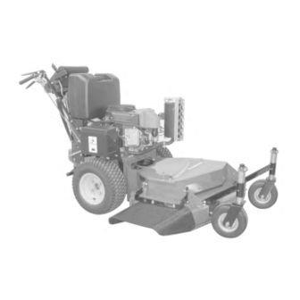
- Page 1 A Textron Company SELF PROPELLED WALK BEHIND LAWN MOWER 933303H 36” REAR DISCHARGE HYDRO MIDSIZE FS541V KAW ES EU 933304H 36” SIDE DISCHARGE HYDRO MIDSIZE FS541V KAW ES EU OPERATOR’S MANUAL 4169944...
- Page 2 CALIFORNIA WARNING Proposition 65 Warning The engine exhaust from this product Diesel engine exhaust and some of contains chemicals known to the State its constituents are known to the State of California to cause cancer, birth of California to cause cancer, birth defects or other reproductive harm.
-
Page 3: Table Of Contents
Ransomes designs and builds its equipment to serve many years in a safe and productive manner. For longest life, use this machine only as directed in the manuals, keep it in good repair and follow safety warnings and instructions. You'll always be glad you did. Textron Golf, Turf & Specialty Products Ransomes Way Ipswich, England, IP3 9QG... -
Page 4: Safety
SAFETY Hydro Midsize NOTICE !!! This symbol means: ATTENTION! Unauthorized modifications may present extreme BECOME ALERT! safety hazards to operators and bystanders and could also result in product damage. Your safety and the safety of others is involved. Ransomes strongly warns against, rejects and disclaims any modifications, add-on accessories or Signal word definitions product alterations that are not designed, developed,... -
Page 5: Assembly/Set-Up Instructions
ASSEMBLY/SET-UP INSTRUCTIONS Hydro Midsize GENERAL NOTE: FRONT, REAR, RIGHT HAND AND LEFT HAND REFERENCES BELOW ARE WITH RESPECT TO AN OPERATOR AT THE CONTROLS. 1. UNCRATE - Place shipping crate on a level surface and remove sides and top. 2. Remove screws securing shipping brackets A to pallet. - Page 6 ASSEMBLY/SET-UP INSTRUCTIONS Hydro Midsize 4. Install upper handle B to lower handle D using (2) 3/8-16 X 1-1/2" bolts and (2) 3/8-16 serrated flange nuts through upper holes F. Install (2) 3/8- 16 X 1 bolts and (2) 3/8-16 locknuts through hole E and one of the three holes on D to give desired handle height.
- Page 7 ASSEMBLY/SET-UP INSTRUCTIONS Hydro Midsize 9. Install spring on bolt A. Repeat for other side. 10. Install 3/8-16 nylon locknut F to end of bolt on both sides as shown. 11. Open the bypass valves X on each pump by rotating handle counter-clockwise two turns. 12.
- Page 8 ASSEMBLY/SET-UP INSTRUCTIONS Hydro Midsize 13. Locate the two longest rods with the single bend removed in Step 3. Install the two traction control rods through the traction control lever H, flatwasher and traction lock J and secure with hairpins. Repeat on other side of upper handle. NOTE: The flat washer in the inside of the traction control lever.
- Page 9 Hydro ASSEMBLY/SET-UP INSTRUCTIONS Midsize 16. Connect speed control rod M to the speed control lever N and secure with hairpin. Repeat for other side. Install swivel to lower end of rods. 17. Set the speed control levers to neutral and adjust the swivel on the lower end of the speed control rod M so they engage the very top of the slot on the neutral plates P and secure with flatwasher...
- Page 10 ASSEMBLY/SET-UP INSTRUCTIONS Hydro Midsize 19. Connect swivel on threaded end of brake rod Q to the brake arm T and secure in place with hairpin S as shown. Adjust swivel to provide adequate braking when the brake control arm is engaged.
- Page 11 ASSEMBLY/SET-UP INSTRUCTIONS Hydro Midsize 22. Fill engine with oil. (See engine manual for specifications.) 23. Fill fuel tank with clean, fresh unleaded fuel. GASOLINE IS HIGHLY FLAMMABLE! • Fill fuel tank with good quality, clean, regular unleaded gasoline. • Do not use hi-test fuel. •...
- Page 12 ASSEMBLY/SET-UP INSTRUCTIONS Hydro Midsize Make all adjustments with the engine shut off, spark 2. CUTTERDECK BLADE SPINDLES plug wire disconnected and mower drive disengaged. NOTE: See MAINTENANCE section of the Setup, FIXED CUTTERDECK HEIGHT OF CUT Parts & Maintenance manual for blade removal and replacement procedures.
- Page 13 Hydro ASSEMBLY/SET-UP INSTRUCTIONS Midsize SETTING CUTTERDECK HEIGHT CUTTERDECK POSITION 1. Support rear of power unit. 2. Place blocks under both outside edges of cutter- deck at B. See Block chart below. " 5 " 5 " " " 5 " 0 "...
-
Page 14: Lubrication
LUBRICATION Hydro Midsize MACHINE LUBRICATION Every 50 Working Hours - Lubricate the following points with grease: 1) Caster wheel pivots (2 points) 2) Neutral eccentric pin (2 points) 3) Idler pivot bearings: a) Engine to cutterdeck belt tensioner b) Cutterdeck belt tensioner c) Hydro drive belt tensioner NOTE: The spindles used on these machines use a superior sealed bearing which does not require relu- brication. - Page 15 LUBRICATION Hydro Midsize ENGINE OIL Do not perform engine maintenance without the engine off, spark plug wires disconnected and PTO disengaged. AFTER FIRST FIVE (5) HOURS While the engine is warm: 1. Release the oil drain hose assembly from the engine clip J.
-
Page 16: Maintenance
MAINTENANCE Hydro Midsize ENGINE - KAWASAKI The maintenance schedule detailed is for average operating conditions. Under extreme conditions (dusty, dirty or more than 8 hrs continuous use) maintain more frequently. Cooling Fins and Air Intake screen (daily) Ensure that the cooling fins and air intake screen W are cleaned daily. - Page 17 MAINTENANCE Hydro Midsize Blade Sharpening Blades may be sharpened by filing or grinding, but with either method the balance of the blades must be maintained at 5/8 oz/in or less. Failure to maintain balance causes excess vibration, wear and shortened life of not only the blades, but most all components of the machine.
- Page 18 MAINTENANCE Hydro Midsize SPARK PLUG Remove plug and check condition. Good operating conditions are indicated if the plug has a light grey or tan deposit. A white blistered coat- ing may indicate overheating. A black coating usually means an “over rich” fuel mixture caused by a clogged air cleaner or improper carburetor adjustment.
-
Page 19: Service Chart
Hydro SERVICE CHART Midsize NOTE: CHANGE ENGINE OIL AND FILTER AFTER FIRST 5 HOURS OF OPERATION. EVERY EVERY EVERY EVERY SERVICE FIRST 5 DAILY HOURS OPERATION HOURS HOURS HOURS HOURS ENGINE Check Oil Level Check for Oil & Air Leaks Clean Air Intake Clean Air Cleaner Change Oil &... -
Page 20: Service Record
SERVICE RECORD Hydro Midsize NOTES ________________________________________________ ________________________________________________ ________________________________________________ ________________________________________________ ________________________________________________ ________________________________________________ ________________________________________________ ________________________________________________ ________________________________________________ ________________________________________________ ________________________________________________ ________________________________________________ ________________________________________________ & & r i f t l i... -
Page 21: Adjustments
ADJUSTMENTS Hydro Midsize TRACTION DRIVE HYDROSTAT ADJUSTMENTS: The following adjustments must be done in order. STEP 1 - Set Neutral Neutral is set at the factory. If it should require adjustment, raise the wheels off the ground by setting the machine on jackstands or blocks. Disconnect the traction control rod A and speed control rod R at each pump end. - Page 22 ADJUSTMENTS Hydro Midsize Make all adjustments with the engine shut off, spark plug wire disconnected and mower drive disengaged. NEUTRAL SWITCH ADJUSTMENT The neutral switch N should be adjusted so that it is engaged by the speed control lever C when in the neutral position, and disengaged just before the wheels being to move by adjusting the speed control lever C from the neutral position to the forward...
- Page 23 Hydro ADJUSTMENTS Midsize OPERATOR PRESENT CONTROLS The operator present (OP) controls should be ad- justed to control the operation of the plunger of the operator present switch (located under the right side of the control panel). Depressing OP levers F should depress the plunger;...
- Page 24 ADJUSTMENTS Hydro Midsize TRACK WIDTH ADJUSTMENT The track width originally set from the factory can be increased an additional 3-1/4" overall by performing the following steps. 1. Loosen wheel lug nuts on both drive tires. 2. Raise rear of unit so that drive tires are off the ground.
-
Page 25: Belt Replacement
BELT REPLACEMENT Hydro Midsize PTO BELT 1. Rotate idler arm using a 3/8" ratchet or breaker bar and remove belt. CUTTERDECK BELT 1. Remove PTO belt. 2. Rotate idler arm using a 3/8" ratchet or breaker bar and remove belt. 3. -
Page 26: Page Intentionally Left Blank
THIS PAGE INTENTIONALLY LEFT BLANK... - Page 27 Hydro Midsize PARTS SECTION...
-
Page 28: Upper Engine Deck Assy
UPPER ENGINE DECK ASSY Hydro Midsize FIGURE 1 TO ENGINE PURGE PORT TO ENGINE G I N WIRE HARNESS... - Page 29 Hydro UPPER ENGINE DECK ASSY Midsize FIGURE 1 ITEM PART NO. DESCRIPTION ITEM PART NO. DESCRIPTION 4167989 CAP-FUEL GASOLINE 3.5 (INCLUDES ITEMS 32-35) 4165561-1 TANK-FUEL 4165864 VALVE-INLINE FUEL 88042-1 CLAMP-HOSE 3/16 88042N HOSE CLAMP 4162977-001 HOSE,FUEL LINE 6A CUT TO 2" LONG 6B CUT TO 18.5"...
-
Page 30: Lower Engine Deck Assy/Clutch
LOWER ENGINE DECK ASSY/CLUTCH Hydro Midsize FIGURE 2... - Page 31 LOWER ENGINE DECK ASSY/CLUTCH Hydro Midsize FIGURE 2 ITEM PART NO. DESCRIPTION ITEM PART NO. DESCRIPTION 2721647 PULLEY-4.50E.O.D. 64163-31 WASHER, 25/64 X 1 X 12 2721110 CLUTCH-ELECTRIC (INCLUDES ITEM 30) 2721331.7 WLDMT-CLUTCH STOP MID 1 2721642 BELT-HA 49.0 2722244 PULLEY- A SECTION 4.50 38304-03 BRG-FLANGED PLASTIC 4121540...
-
Page 32: Drive Wheels
DRIVE WHEELS Hydro Midsize FIGURE 3... - Page 33 DRIVE WHEELS Hydro Midsize FIGURE 3 ITEM PART NO. DESCRIPTION ITEM PART NO. DESCRIPTION 4169053.2 DECK-ENGINE HYDRO 2721620 WLDMT-HUB 970438 KIT-WHEEL HUB PULLER 2721956 ASSY-WHEEL 16 X 7.50 X 8 2 2721956-01 TIRE-16X7.50 X 8 MLTI TRC 1 2721956-02 WHEEL W/ DUAL VALVES 64187-03 NUT-WHEEL 1/2-20 64025-06...
-
Page 34: Parking Brake/Document Tube
PARKING BRAKE/DOCUMENT TUBE Hydro Midsize FIGURE 4... - Page 35 PARKING BRAKE/DOCUMENT TUBE Hydro Midsize FIGURE 4 ITEM PART NO. DESCRIPTION ITEM PART NO. DESCRIPTION 4169790.7 WLDMT-BRAKE SHAFT 33103 SWIVEL 64168-2 COTTER-HAIRPIN.08X1.19 2 64001-6 NUT-HEX JAM,3/8-16 64262-025 BLT-FLG HD 3/8-16 X 2-1/2 2188131 SPRING-EXTENSION 2183071-01 SPACER-15.88X10.32X16 64171-2 WAVE WASHER 4131072.7 PLATE-BRK SHFT RETNR 64123-50 BOLT-HEX 3/8-16X1...
-
Page 36: Electric Start Upper Handle
ELECTRIC START UPPER HANDLE Hydro Midsize FIGURE 5... - Page 37 ELECTRIC START UPPER HANDLE Hydro Midsize FIGURE 5 ITEM PART NO. DESCRIPTION ITEM PART NO. DESCRIPTION 4169953 S-UPPR HNDL W/LABELS, ES 1 4169316.7 HNDL-OPER PRESENT, RH 128010 SWITCH-ENGINE 64152-46 SCR-SLT HH 10-24X1/2 64163-60 WSHR.50X.203X18GA 2303023 CONNECTOR-OP 4122104 ROD-HANDLE LINK, LH 4122107 ROD-HANDLE LINK, RH 64168-2...
-
Page 38: Traction Controls
TRACTION CONTROLS Hydro Midsize FIGURE 6... - Page 39 TRACTION CONTROLS Hydro Midsize FIGURE 6 ITEM PART NO. DESCRIPTION ITEM PART NO. DESCRIPTION 64268-03 NUT-FLG LYLOCK 3/8-16 64123-70 BOLT-HEX 3/8-16X1-1/2 38189 SPRING-COMPRESSION 64141-4 NUT-WLF 3/8-16 64061-37 ROLL PIN-1/8 X 1.00 SS 64123-202 BLT-HEX 3/8-16 X 9 4170012 STUD-LATCH 64229-03 NUT-NYLOCK 3/8-16 62464-5A WASHER,THRUST 5/16X3/4...
-
Page 40: Electric Start Battery
ELECTRIC START BATTERY Hydro Midsize FIGURE 7... - Page 41 ELECTRIC START BATTERY Hydro Midsize FIGURE 7 ITEM PART NO. DESCRIPTION ITEM PART NO. DESCRIPTION 64229-02 LOCKNUT-NYLON 5/16-18 64163-29 WASHER 128035 COVER-BATTERY 4131068.2 DECK-ENGINE HYDRO 64123-54 BLT-HEX 5/16-18X3/4 112386 BOOT-BATTERY TERM POS 1 BATTERY (OBTAIN LOCALLY) 108061-16 CABLE-BTTRY 31.5 BLACK 1 64025-02 NUT-HEX 5/16-18 4115331...
-
Page 42: Hydraulics
HYDRAULICS Hydro Midsize FIGURE 8... - Page 43 Hydro HYDRAULICS Midsize FIGURE 8 ITEM PART NO. DESCRIPTION ITEM PART NO. DESCRIPTION 58026-01 3-WAY CONNECTOR 108029 PLUG, MAGNETIC SERVICEABLE HYDRAULIC O-RINGS 158058-04 FITTING-90 BARB, ADJ. 108205-02 ELBW-MALE 45 8X8 37-ORB 4 88042-04 CLAMP-HOSE 5/8" SAE PORT 'O' RING 2720396 FLTR, 25 MCRN SM CAM 69060-01 FTG-BARB 9/16 X 3/8 ST...
-
Page 44: Power Unit Decals
POWER UNIT DECALS Hydro Midsize FIGURE 9... - Page 45 POWER UNIT DECALS Hydro Midsize FIGURE 9 ITEM PART NO. DESCRIPTION ITEM PART NO. DESCRIPTION 4169935 LABEL-CNTRL PNL EC HYD 4127946 LABEL-DECK,RANSOMES 2000664 LABEL-HYDRAULIC MS EEC 2000655 LABEL-READ OPRTRS EEC 2000650 LABEL-BATTERY EEC 2000760 LABEL-HANDS/ROCKS EC 4110260 LABEL-TRACKING CONTROL 1 2000638 LABEL-CON WASHER EEC 4162912...
-
Page 46: Wire Diagram-Electric Start
WIRE DIAGRAM-ELECTRIC START Hydro Midsize FIGURE 10... - Page 47 WIRE DIAGRAM-ELECTRIC START Hydro Midsize FIGURE 10 ITEM PART NO. DESCRIPTION ITEM PART NO. DESCRIPTION 2721110 CLUTCH-ELECTRIC (INCLUDES ITEM 2) 2720949 ASSY-CLUTCH WIRE 108208 SWITCH DBL POLE 128010 KEY SWITCH 2308094 SWITCH-NCNC DBL POLE 148082-20 FUSE 20 AMP 2721505 SWITCH-PTO 4166693 HARNESS-HYDRO MAIN (INCLUDES QTY OF 2 OF ITEM 6)
-
Page 48: Wiring Schematic-Electric Start
WIRING SCHEMATIC-ELECTRIC START Hydro Midsize FIGURE 11 REF. 4115550... -
Page 50: Spindle Assembly
SPINDLE ASSEMBLY Hydro Midsize FIGURE 12... - Page 51 SPINDLE ASSEMBLY Hydro Midsize FIGURE 12 ITEM PART NO. DESCRIPTION ITEM PART NO. DESCRIPTION 4167554-01 BEARING-SPINDLE SEALED 2 33179-02 SPINDLE-SHORT (USED IN ITEM 8) 33179-01 SPINDLE-LONG (USED IN ITEM 7) 2721096 HOUSING-SPINDLE 6 HOLE 64144-38 SNAP-RING 38315 NUT-SPINDLE 4171185 ASSY-SPINDLE LONG (INCLUDES ITEMS 1, 3, 4-6) 4171184 ASSY-SPINDLE SHORT...
- Page 52 HYROGEAR PUMP Hydro Midsize FIGURE 13...
-
Page 53: Hydrogear Pump
HYDROGEAR PUMP Hydro Midsize FIGURE 13 4112782 & 4163317 PUMP-HYDRO RH ILLUSTRATED AS SHOWN 2721615 & 4163316 PUMP-HYDRO LH ILLUSTRATED AS SHOWN EXCEPT GROUP A IS ROTATED 180° AROUND THE CENTERLINE OF THE PUMP. ITEM HYDROGEAR PART NO. PART NO. DESCRIPTION 70516 -----... -
Page 54: Mounting-36" Side Discharge Deck
MOUNTING-36" EC SIDE DISCHARGE DECK Hydro Midsize FIGURE 14... - Page 55 MOUNTING-36" EC SIDE DISCHARGE DECK Hydro Midsize FIGURE 14 ITEM PART NO. DESCRIPTION ITEM PART NO. DESCRIPTION 112243-02 BLADE 18.00 OFFST 64164-12 KEY-1/4X1/4X1 SQ END 128169 PULLEY, IDLER 5.50 64164-13 1/4X1/4X2 SQ KEY 4163871.7 WLDMT-DECK IDLER 64209-03 SPRING WASHER.67 ID 2306029 S CASTER SUPPORT 64215-12...
-
Page 56: Mounting-36" Rear Discharge Deck
Hydro 36" EC REAR DICHARGE DECK Midsize FIGURE 15... - Page 57 Hydro 36" EC REAR DISCHARGE DECK Midsize FIGURE 15 ITEM PART NO. DESCRIPTION ITEM PART NO. DESCRIPTION 4115087 S-36 DECK RD W/LABS EC 1 64229-05 LOCKNUT, 1/2-13 NYLON 2721323 ASSY-SPINDLE SHORT 2722161 PULLEY-6.75 EOD (SEE FIGURE 5 FOR COMPONENTS) 2720815 BELT-PTO 48 64123-74 BLT-HEX 1/2-13 X 4-1/2...
- Page 58 BAFFLES-SIDE DISCHARGE Hydro Midsize FIGURE 16...
-
Page 59: Baffles
BAFFLES-SIDE DISCHARGE Hydro Midsize FIGURE 16 ITEM PART NO. DESCRIPTION ITEM PART NO. DESCRIPTION 64018-2 BLT-CRG 1/4-20X3/4 64018-3 BLT-CRG 3/8-16X1 64123-50 BOLT-HEX 3/8-16X1 4134343.7 BAFFLE-RIGHT FRONT 64229-01 LOCKNUT-1/4-20 NYLON 64268-03 NUT-FL NYLON LOCK 3/8-16 6 4115864.7 BAFFLE-DISCHARGE 4147035.7 BAFFLE-FRONT DECK... -
Page 60: Caster Assy-Fixed Decks
CASTER ASSY-FIXED DECKS Hydro Midsize FIGURE 17... - Page 61 CASTER ASSY-FIXED DECKS Hydro Midsize FIGURE 17 ITEM PART NO. DESCRIPTION ITEM PART NO. DESCRIPTION 64173-04 QUICK PIN 64163-07 1-1/32X1-3/4X1/4 WASH 64163-22 1-1/32X1-3/4X1/2 WASHR 4129801 BUSHING-FLANGED 2306029 S CASTER SUPPORT (INCLUDES ITEMS 4 & 6, QTYs LISTED) 85010N ZERK GREASE FITTING 4165543-01 S-ASSY WHEEL HUB 2721484.7...
- Page 62 Textron Golf, Turf & Specialty Products P.O. Box 82409 A Textron Company Lincoln, Nebraska 68501-2409...
Need help?
Do you have a question about the Ransomes 933303H and is the answer not in the manual?
Questions and answers