Advertisement
Quick Links
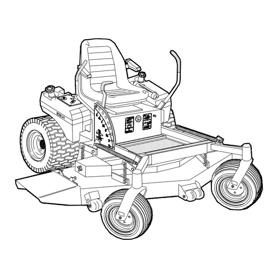
SETUP, PARTS & MAINTENANCE
MANUAL ZT 200 EFI SERIES
Models:
942230
ZT 226EFI 26HP KLR W/61 SIDE DISCHARGE
942231
ZT 226EFI 26HP KLR W/72 SIDE DISCHARGE
WARNING: If incorrectly used this machine can cause severe injury. Those who use
and maintain this machine should be trained in its proper use, warned of its dangers
and should read the entire manual before attempting to set up, operate, adjust or
service the machine.
Operation & Safety Manual: 2722182
2722183 REV D
Advertisement

Related Manuals for Textron BOB-CAT ZT 200 EFI Series


Summary of Contents for Textron BOB-CAT ZT 200 EFI Series
- Page 1 SETUP, PARTS & MAINTENANCE MANUAL ZT 200 EFI SERIES Models: 942230 ZT 226EFI 26HP KLR W/61 SIDE DISCHARGE 942231 ZT 226EFI 26HP KLR W/72 SIDE DISCHARGE WARNING: If incorrectly used this machine can cause severe injury. Those who use and maintain this machine should be trained in its proper use, warned of its dangers and should read the entire manual before attempting to set up, operate, adjust or service the machine.
- Page 2 © 2002, TEXTRON INC...
- Page 3 You'll always be glad you did. Textron Golf, Turf & Specialty Products One Bob Cat Lane Johnson Creek, WI 53038-0469...
- Page 4 These words appear in this alterations that are not designed, developed, tested manual and on the safety labels attached to Textron and approved by Textron Golf, Turf & Specialty Products Engineering Department. Any Textron Golf, Turf &...
- Page 5 ZT 200 ASSEMBLY AND SETUP Series TOOLS REQUIRED FOR ASSEMBLY – Wrecking bar – Claw hammer – Ratchets: 3/8" – Sockets: 3/8", 1/2", 17 mm, 19 mm – Wrenches: two 15/16" (or adjustable), 13 mm, 17 mm, 19 mm – Level –...
- Page 6 ZT 200 ASSEMBLY AND SETUP Series 2. Set tire pressures to 14 lbs/in (1.0 kg/cm ). Tires are overinflated for shipping. 3. LEVEL CUTTERDECK AND ADJUST COUNTERBALANCE SPRINGS – Side Discharge: The front of a side discharge deck should be slightly lower than the rear. –...
- Page 7 ZT 200 ASSEMBLY AND SETUP Series 4. TRACTION LEVERS a) Remove bolt A. b) Rotate traction lever B into position and secure with bolt A. Repeat for the other lever. c) Tighten all fasteners. d) Sit on the machine. If the levers are too long, bracket C may be removed to make them shorter.
- Page 8 ZT 200 MAINTENANCE CHART Series t l i t l i Consult the manufacturer's manual for your engine for further information and instructions.
- Page 9 ZT 200 MAINTENANCE RECORD Series NOTES _______________________________________________________________ ____________________________________________________ ________________________________________________________________________ _______________________________________________________________ ____________________________________________________________ ____________________________________________________ ________________________________________________________________________ _______________________________________________________________ ____________________________________________________________ _______________________________________________________________ ____________________________________________________________ ____________________________________________________________ & & r i f , l i t l i...
- Page 10 ZT 200 MAINTENANCE Series CHECK DAILY Operator Presence Interlock System - Start Operation For the engine to crank, the parking brake must be on, the PTO (blades) off and traction levers in the neutral lock position. Sit in the seat and check, one by one, if the engine will crank with the parking brake off, the blades on, and either traction lever out of neutral lock.
- Page 11 ZT 200 MAINTENANCE Series LUBRICATION Every 50 hours of operation, lubricate the following points (1-6) with grease: 1. Deck lift rockshaft (1 point) 2. Deck idler pivot bearings (2 points) 3. Deck lift pivots (6 points) 4. Hydro belt tensioner (1 point under engine deck) 5.
- Page 12 ZT 200 MAINTENANCE Series HYDRAULIC SYSTEM Fluid level in the hydraulic system should be checked every 100 hours or when a leak has occurred. If the fluid is low, check all components for leaks. To check, remove reservoir cap M. The fluid level should be at the bottom of the filler tube.
- Page 13 ZT 200 MAINTENANCE Series ENGINE OIL Do not perform engine maintenance without the engine off, spark plug wires disconnected and PTO disengaged. AFTER FIRST FIVE (5) HOURS While the engine is warm: 1. Remove drain cap D and drain the crankcase. Dispose of used oil in accordance with local requirements.
- Page 14 ZT 200 MAINTENANCE Series FUEL SYSTEM Before attempting to service any part of the fuel system, the pressure must be relieved. Refer to section 5B of the engine manual. A low pressure filter C is located on the kickplate as shown.
- Page 15 ZT 200 MAINTENANCE Series AIR CLEANER Clean and replace the air cleaner element as specified in the service chart. Uneven running, lack of power or black exhaust fumes may indicate a dirty air cleaner. To replace air cleaner elements: 1. Unclamp end cover X and remove existing cleaner elements.
- Page 16 ZT 200 MAINTENANCE Series BLADE BALANCE BLADE REMOVAL Follow these instructions to prevent injury during Blade balance must be maintained at 5/8 oz-in (19.4 blade removal: g-cm) or less. Failure to keep blades balanced causes excess vibration, wear, and shortened life of 1.
- Page 17 ZT 200 ADJUSTMENTS Series HEIGHT OF CUT The height of cut is set by moving height of cut pin N to the hole designated for the height of cut desired. To change the height of cut: 1. Lift the deck to the highest position. 2.
- Page 18 ZT 200 ADJUSTMENTS Series PUSH ARMS The push arm rod ends must be adjusted evenly to: – locate the deck perpendicular to the front-to-rear axis of the machine; and – so the notch at the front of the engine deck clears the push arm bracket on the rear of the cutterdeck when the cutterdeck is raised to the transport position.
- Page 19 ZT 200 ADJUSTMENTS Series DECK LEVELING AND COUNTERBALANCE SPRINGS NOTE: These instructions are in regards to both sides of the deck. To level deck: 1. Park the machine on a smooth, level surface. Remove the height of cut pin A and raise the cutterdeck to the 3"...
- Page 20 ZT 200 ADJUSTMENTS Series PARKING BRAKE Start with parking brake N in the OFF position. 1. Disconnect one end of rods M (at brakes on both sides of the machine). 2. Move the parking brake lever to the ON position. 3.
- Page 21 ZT 200 ADJUSTMENTS Series HYDROSTAT ADJUSTMENTS A turnbuckle-style hydrostat neutral adjustment is provided. Neutral: 1. Support the machine with the rear wheels off the ground. Use jackstands or equivalent support. Do not rely only on mechanical or hydraulic jacks. 2. Move the traction levers out into the neutral lock position and raise the seat.
- Page 22 ZT 200 BELT REPLACEMENT Series Note: Always use Bob-Cat replacement belts, not general purpose belts. Bob-Cat belts are specially designed for use on commercial mowers and will normally last longer. ENGINE-CUTTERDECK (PTO) BELT 1. Set the cutterdeck in the lowest height-of-cut position.
- Page 23 ZT 200 BELT REPLACEMENT Series 61” CUTTERDECK BELT 1. Set the cutterdeck in the lowest height-of-cut position. 2. Remove the engine-cutterdeck belt from the deck idlers and pulley (see engine-cutterdeck belt replacement). Push it aside but don't remove it from the machine. 3.
- Page 24 ZT 200 SPECIFICATIONS Series POWER UNITS ENGINES : CONTROLS: Construction: Aluminum block with cast-in cast iron Throttle; power takeoff (PTO) clutch switch; traction sleeves. Aluminum head. levers; parking brake lever; lift lever. Configuration: 4-stroke, vertical shaft, V-twin FUEL SYSTEM: cylinder, overhead valve, air-cooled or liquid cooled. One tank on each side of operator, each with a shutoff (1/4 turn).
- Page 25 ZT 200 SPECIFICATIONS Series " 4 . n i - t f / . l h / l . l a...
- Page 26 ZT 200 SPECIFICATIONS Series " 0 " 5 " 0 " 5 " 0 " 0 t f i l t f i l t f i l o i t t f i l o i t " 0 "...
- Page 27 ZT 200 PARTS SECTION Series PARTS SECTION...
- Page 28 ZT 200 UPPER ENGINE DECK ASSY Series FIGURE 1...
- Page 29 ZT 200 UPPER ENGINE DECK ASSY Series FIGURE 1 2722183-01 ITEM PART NO. DESCRIPTION ITEM PART NO. DESCRIPTION 4114447 ENGINE-KOHLER CV26S 1-42 64205-007 BLT-M10-1.5x20 4114747 S-FILTER, SECONDARY AIR 1 1-43 64163-55 WASHER .328X.75X14 GA 4114746 S-FILTER, PRIMARY AIR 1-44 2188146 STRIP, WEAR 842502 FILTER-OIL...
- Page 30 ZT 200 LOWER ENGINE DECK ASSY/CLUTCH Series FIGURE 2...
- Page 31 ZT 200 LOWER ENGINE DECK ASSY/CLUTCH Series FIGURE 2 2722087-02 ITEM PART NO. DESCRIPTION ITEM PART NO. DESCRIPTION 2722382 PUMP-PULLEY 64044-1 SCREW-SET 1/4-20X1/4 64238-03 KEY-MET 5mm SQX28mm 64164-10 1/4X1/4X1 1/4 SQ END KEY 1 4121339 PULLEY-4.25 ENGINE 2721337 CLUTCH-ELECTRIC (INCLUDES 2720949 WIRE ASSY) 2721338.7 WLDMT-CLUTCH STOP 2186147.7 WLDMT-BRKT CLUTCH 38304-03...
- Page 32 ZT 200 BELTS Series FIGURE 3...
- Page 33 ZT 200 BELTS Series FIGURE 3 2722185-19 ITEM PART NO. DESCRIPTION ITEM PART NO. DESCRIPTION 128003 BELT-CUTTERDECK 2722224 BELT-PTO (USE ON 61" DECKS ONLY) 3970215 BELT-BLADE TO BLADE 2722554 BELT-PTO (USE ON 72" SD DECKS ONLY)
- Page 34 ZT 200 DECALS Series FIGURE 4...
- Page 35 FIGURE 4 2722183-04 ITEM PART NO. DESCRIPTION ITEM PART NO. DESCRIPTION 2721971 LABEL-BOBCAT DIECUT 2721807 LABEL-BOBCAT TEXTRON 1 2000735 LABEL-OPER MAN 2000590 LABEL, WARN BATTERY 2000691 LABEL - HYDR OIL FILL 2000784 LABEL-CONTROL PANEL 2000693 LABEL - PARK BRAKE 2000698...
- Page 36 ZT 200 BUMPER Series FIGURE 5...
- Page 37 ZT 200 BUMPER Series FIGURE 5 2722183-05 ITEM PART NO. DESCRIPTION ITEM PART NO. DESCRIPTION 2722296.7 ARM-BUMPER 2720996 S ENG DECK W/LABS 2721324.7 WLDMT-BUMPER 64263-013 BLT-FLG HD M10-1.5 X 30 (QTY 12 USED ON 61") (QTY 6 USED ON 72") 64265-05 NUT-FL NYLN LCK M10-1.5 10 2721932-7 BRACE-VERTICAL...
- Page 38 ZT 200 BRAKES/REAR WHEEL Series FIGURE 6...
- Page 39 ZT 200 BRAKES/REAR WHEEL Series FIGURE 6 2722183-06 ITEM PART NO. DESCRIPTION ITEM PART NO. DESCRIPTION 2720996 S ENGINE DECK W\LABS 6-25 64141-4 NUT-WLF 3/8-16 4113527.7 WLDMT-BRAKE ARM LH 6-26 64025-03 NUT-HEX 5/16-24 4113529.7 WLDMT-BRAKE ARM RH 6-27 64168-2 HAIRPIN COTTER 128102 SPRING-EXTENSION 6-28...
- Page 40 ZT 200 HYDRAULICS Series FIGURE 7...
- Page 41 ZT 200 HYDRAULICS Series FIGURE 7 2722183-07 ITEM PART NO. DESCRIPTION ITEM PART NO. DESCRIPTION 2186211 S HYD RESERVOIR W/LAB 1 2720396 FILTER 25 MICRON 69216.7 CAP-RESERVOIR 108029 PLUG-MAGNETIC 158058-04 FTG-90 BRB 9/16-18X.38 108205-03 ELBOW-MALE 45 37-ORB (69053-05 IS A SERVICEABLE LENGTH OF 55") 7-7A 69053-05 3/8 HIGH TEMP HOSE 22"...
- Page 42 ZT 200 HYDROGEAR PUMP Series FIGURE 8...
- Page 43 HYDROGEAR PUMP Series FIGURE 8 2722087-08 2721615 PUMP-HYDRO RH ILLUSTRATED AS SHOWN EXCEPT GROUP A IS ROTATED 180° AROUND THE CENTERLINE OF THE PUMP. ITEM HYDROGEAR PART NO. TEXTRON PART NO. DESCRIPTION 70516 ----- HOUSING KIT 70517 ----- END CAP KIT...
- Page 44 ZT 200 DECALS-CUTTERDECKS Series FIGURE 9...
- Page 45 ZT 200 DECALS-CUTTERDECKS Series FIGURE 9 2722183-09 ITEM PART NO. DESCRIPTION ITEM PART NO. DESCRIPTION 2000572 LABEL-WARNING BLADES 1 (USED ON 61" DECKS ONLY) 2000577 LABEL, WARNING 2000696 LBL - BLADE INSTALL (USED ON 61" DECKS ONLY) 2000677 LABEL-DANGER/WARNING (USE QTY 2 ON 72" DECKS) (USE QTY 1 ON 61"...
- Page 46 ZT 200 KOHLER WIRE HARNESS Series FIGURE 10 2722185-10 ITEM PART NO. DESCRIPTION ITEM PART NO. DESCRIPTION 10-1 2722316 HARNESS-WIRING MAIN EFI1 10-2 148082-20 FUSE-20 AMP 10-3 108061-13 CABLE-BATTERY 10-4 158135-01 SWITCH-SEAT NO 10-5 158136 WIRE-SEAT SWITCH 10-6 48030N HOUR METER ASSY 10-7 2722227-02 CABLE-BATT W/CONDUIT (INCLUDES ITEMS 16 &...
- Page 47 KOHLER WIRE HARNESS BZT 2000 EFI Series FIGURE 10 2722185-10...
- Page 48 ZT 200 FUEL TANKS/CONTROL PANEL Series FIGURE 11...
- Page 49 ZT 200 FUEL TANKS/CONTROL PANEL Series FIGURE 11 2722183-11 ITEM PART NO. DESCRIPTION ITEM PART NO. DESCRIPTION 11-1 2722245 S-LH FUEL TANK 11-37 2722117 FILTER-FUEL (INCLUDES ITEMS 12,18 & 19) 11-38 FUEL PUMP (AVAILABLE THRU KOHLER) 11-2 2722246 S-RH FUEL TANK (INCLUDES ITEMS 12,18 &...
- Page 50 ZT 200 CRADLE ASSEMBLY Series FIGURE 12...
- Page 51 ZT 200 CRADLE ASSEMBLY-72" Series FIGURE 12 2722183-12 ITEM PART NO. DESCRIPTION ITEM PART NO. DESCRIPTION 12-1 2000695 LABEL-WARN/USING 12-2 2182356.7 BRKT-SHAFT HANGER 12-3 2188127 CHAIN-6.35 5 LINKS 12-4 2721859 MAT-FOOT PLATE LOWER 1 12-5 2721860 MAT-FOOT PLATE MIDDLE 1 12-6 2721861 MAT-FOOT PLATE UPPER...
- Page 52 ZT 200 OIL COOLER/ECU Series FIGURE 13...
- Page 53 ZT 200 OIL COOLER/ECU Series FIGURE 13 2722183-13 ITEM PART NO. DESCRIPTION ITEM PART NO. DESCRIPTION 13-1 2720996 S ENGINE DECK W/LABS 13-2 2722339.7 BRKT-FRONT COOLER 13-3 2722338.7 BRKT-OIL COOLER 13-4 2720891.7 SCREEN-OIL COOLER 13-5 2188173 COOLER-OIL 13-6 2186211 S HYD RSRVR W/LABS (69053-05 IS A SERVICEABLE LENGTH OF 55") 13-7A 69053-05 3/8 HIGH TEMP HOSE 26"...
- Page 54 ZT 200 SEAT ASSEMBLY & ROPS Series FIGURE 14...
- Page 55 ZT 200 SEAT ASSEMBLY & ROPS Series FIGURE 14 2187026 ITEM PART NO. DESCRIPTION ITEM PART NO. DESCRIPTION 14-1 2720975 SEAT-SUSPENSION (INCLUDES ITEMS 2-10) 2720975-01 SEAT CUSHION 2720975-02 BACK CUSHION 2720975-05 CABLE ASSEMBLY (INTERNAL SEAT COMPONENT NOT ILLUSTRATED) 2720975-08 ASSY-SEAT BACK PANEL 14-2 2721093 RH ARM REST...
- Page 56 ZT 200 STEERING/DECK LIFT Series FIGURE 15...
- Page 57 ZT 200 STEERING/DECK LIFT Series FIGURE 15 2722183-15 ITEM PART NO. DESCRIPTION ITEM PART NO. DESCRIPTION 15-1 2720996 S ENGINE DECK W/LABS 15-2 48030N HOUR METER ASSY 15-3 2722121 LAMP-ENG MALFUNCT IND 1 2722121-01 BULB 15-4 64205-008 BLT-MET M10-1.50X55 15-5 2182344.7 LEVER-CONTROL 15-6 2182434.7 BRKT-TRACTION LEVER...
- Page 58 ZT 200 CRADLE & CASTER ASSEMBLY Series FIGURE 16...
- Page 59 ZT 200 CRADLE & CASTER ASSEMBLY Series FIGURE 16 2722183-16 ITEM PART NO. DESCRIPTION ITEM PART NO. DESCRIPTION 16-1 48043-03C S CUP,OUTER BEARING 16-2 64123-223 BLT-3/4-10X10 16-3 2722723.2 WLDMT-CRADLE 16-4 2721710 WLDMT-CUTTERDECK 61" 1 16-5 2720690 S-72" DECK W/LABS 16-6 2722228 WHEEL-13X5.00-6 ASSY (INCLUDES ITEMS 7-9)
- Page 60 ZT 200 61" SIDE DISCHARGE Series FIGURE 17...
- Page 61 ZT 200 61" SIDE DISCHARGE Series FIGURE 17 2722183-17 ITEM PART NO. DESCRIPTION ITEM PART NO. DESCRIPTION 17-1 2721710 WLDMT-DECK 61SD 17-45 64123-209 BLT-HEX 5/8-18X3.5 17-2 64163-64 WSHR 1.015X1.500X14GA 17-46 64123-208 BLT-HEX 5/8-11X1 1/2 17-3 64237-05 LOCKNUT-NYLON M8-1.25 17-47 32767.7 SUPPORT-BELT 17-4 38524...
- Page 62 ZT 200 72" SIDE DISCHARGE Series FIGURE 18...
- Page 63 ZT 200 72" SIDE DISCHARGE Series FIGURE 18 2722183-19 ITEM PART NO. DESCRIPTION ITEM PART NO. DESCRIPTION 18-1 163425 ROLLER 18-51 64123-39 BLT-HEX 1/2-13X1-1/4 18-2 198027 PULLEY-6.00 DIA 18-52 64123-50 BOLT, 3/8-16X1 HEX 18-3 1985108 PULLEY- IDLER STATIONRY 1 18-53 64123-88 BOLT, 3/8-16X2-3/4 HEX 18-4...
Need help?
Do you have a question about the BOB-CAT ZT 200 EFI Series and is the answer not in the manual?
Questions and answers