Sign In
Upload
Manuals
Brands
Cebora Manuals
Welding System
PLASMA PROF 162
Cebora PLASMA PROF 162 Manuals
Manuals and User Guides for Cebora PLASMA PROF 162. We have
1
Cebora PLASMA PROF 162 manual available for free PDF download: Service Manual
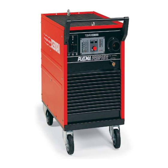
Cebora PLASMA PROF 162 Service Manual (39 pages)
POWER SOURCE art. 952
Brand:
Cebora
| Category:
Welding System
| Size: 1 MB
Table of Contents
Table of Contents
2
1 General Information
4
Introduction
4
General Service Policy
4
Safety Information
4
Electromagnetic Compatibility
4
2 System Description
5
Introduction
5
Technical Specifications
5
Description of Power Source Art. 952
5
3 Maintenance
8
Periodic Inspection, Cleaning
8
Operating Sequence
8
Power Source Commands and Signals
10
Troubleshooting
10
The Power Source Does Not Start, Operator Panel (64) off
10
Power Source Powered, Operator Panel (64) On, Fan (77) Stopped
12
Power Source Powered, Display and Signals Doe Not Indicate the Correct Values
13
The Start Button Produces no Effect
13
No Gas Flows from the Torch
15
Gas Flows from the Torch, Pilot Arc Does Not Light (IGBT Output Voltage Missing)
16
Gas Flows from the Torch, the Pilot Arc Does Not Light (High Frequency Missing)
17
Irregular Pilot Arc Starts, Unstable Pilot Arc
18
Transfer Arc Does Not Take Place, Pilot Arc Remains and Cutting Is Impossible
20
Weak Transfer Arc that Shuts off as Soon as Cutting Begins
21
Post-Gas Does Not Take Place Upon Releasing the Start Button and after Cutting
21
Error Messages
22
E1 - Hardware Lockup
22
E2 - Hardware Lockup
22
E12 - Transfer Reed Closed During Start-Up
22
E13 - Hazardous Voltage on the Torch
22
E51 - Torch Not Recognized
23
E52 - Start Button Pressed During Start-Up
23
E53 - Start Button Pressed While Resetting from Stop Due to Pressure or Temperature Beyond Allowable Limits
23
E54 - Short-Circuit between Electrode and Nozzle
24
E55 - Electrode Finished
24
4 Components List
25
Power Source Art. 952 : See File Esp952.Pdf Enclosed at the End of the Manual
25
Components Table: See File Esp952.Pdf Enclosed at the End of the Manual
25
Spare Parts List
25
5 Electrical Diagrams
26
Power Source Art. 952 : See File Sche952.Pdf Enclosed at the End of the Manual
26
Waveforms
26
Pilot Arc Current Set-Point (Par.3.3.6 - 3.3.8)
26
Pilot Arc Current Feed-Back (Par. 3.3.8)
26
Transfer Arc Current Set-Point (Par. 3.3.9)
26
Fuse Board (8) Code 5.602.025
27
Topographical Drawing
27
Connector and Fuse Table
27
Pre-Charge Board (7) Code 5.602.026/A
28
Topographical Drawing
28
Connector and Fuse Table
28
Control Board (62) Code 5.602.027/A
29
Topographical Drawing
29
Connector Table
29
Driver Board (9) Code 5.602.023/A
30
Topographical Drawing
30
Connector Table
30
HF Board (15) Code 5.602.024
31
Topographical Drawing
31
Connector Table
31
Torch Board (68) Code 5.602.022/A
32
Topographical Drawing
32
Connector Table
32
Operator Panel Board (64) Code 5.602.028
33
Topographical Drawing
33
Connector Table
33
6 Upgrades
34
Power Source Art. 952 with Enhanced Pilot Arc Lighting
34
Description of Upgrade
34
Operating Description
34
RC Board Code 5.602.076
34
Power Source Art. 952 + RC Board Upgrade: See File SCHE952-A.pdf Enclosed at the End of the Manual
34
Advertisement
Advertisement
Related Products
Cebora PLASMA PROF 164 HQC
Cebora PLASMA PROF 163 ACC
Cebora PLASMA PROF 37
Cebora Plasma PROF 166 HQC
Cebora Plasma PROF 255 HQC
Cebora PLASMA PROF 122
Cebora PLASMA PROF 152
Cebora PLASMA PROF 123 ACC
Cebora PLASMA PROF 80
Cebora PLASMA PROF 123
Cebora Categories
Welding System
Portable Generator
Welding Accessories
Recording Equipment
Control Panel
More Cebora Manuals
Login
Sign In
OR
Sign in with Facebook
Sign in with Google
Upload manual
Upload from disk
Upload from URL