Table of Contents
Advertisement
Quick Links
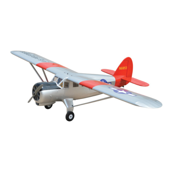
NOORDUYN NORSEMAN
ALL BALSA - PLY WOOD CONSTRUCTION.
COVERED WITH ORACOVER.
95% ALMOST READY TO FLY
SPECIFICATION
- Wingspan: 1840 mm (72.44 in).
- Length: 1180 mm (46.46in).
- Weight: 3.2kg ( 7.04lbs).
- Wing area: 46.2dm
- Wing loading: 69.26g/dm
- Wing type: Naca Airfoil.
- Gear type: Aluminium Hi-grade
for main gear (included).
- Servo mount: 42mm x 21mm.
Instruction Manual Book
Parts listing required (not included):
- Radio: 05 channels.
- Servo: 07 servos.
- Engine: 55 - 2 stroke.
.
2
- Motor: Brushless outrunner 1000-1800W, 800KV.
.
2
- Propeller: Suit with your engine.
Recommended Motor
and Battery set up (not included):
- Motor: RIMFIRE.55 .
- Receiver battery: 6V/ 1200-2000mAh NiMH.
- Lipo cell: 6 cells 4,000-5,000mAh.
- ESC: 60A.
Item code: BH157.
Made in Vietnam.
Advertisement
Table of Contents

Subscribe to Our Youtube Channel
Related Manuals for Black Horse Model NOORDUYN NORSEMAN


Summary of Contents for Black Horse Model NOORDUYN NORSEMAN
- Page 1 Instruction Manual Book Item code: BH157. NOORDUYN NORSEMAN ALL BALSA - PLY WOOD CONSTRUCTION. COVERED WITH ORACOVER. 95% ALMOST READY TO FLY SPECIFICATION Parts listing required (not included): - Wingspan: 1840 mm (72.44 in). - Radio: 05 channels. - Length: 1180 mm (46.46in).
-
Page 2: Tools And Supplies Needed
(1) Fuselage. erly before gluing! This will assure proper assembly. NOORDUYN NORSEMAN ARF is hand made from natural materials, every plane is unique and minor ad- WINg ASSEMBLY justments may have to be made. However, you should (1) Right wing half with pre-installed aileron. -
Page 3: Safety Precaution
NOORDUYN NORSEMAN Item code: BH157. Instruction Manual Caution: necessary. If the air or the iron is too hot, the film may This model is not a toy! melt and holes may be formed. If you are a beginner to this type of powered model,... -
Page 4: Installing The Aileron Servos
NOORDUYN NORSEMAN Item code: BH157. Instruction Manual REPLACEMENT SMALL PARTS 3x12mm 3x15mm 4x15mm 3x8mm 5x35mm 3x12mm 2x10mm 1. Plastic fairing for landing gear (1a, 1b). 2. Wheels. 3. Tail gear set. 4. Plywood of wing struts. 5. Fuel Tank. 3x25mm 5a. -
Page 5: Installing The Aileron Linkages
NOORDUYN NORSEMAN Item code: BH157. Instruction Manual 3) Place the servo into the servo tray. Center the servo within the tray and drill 1.5mm pilot holes through the block of wood for each of the four mount- ing screws provided with the servo. -
Page 6: Installing The Engine Mount
NOORDUYN NORSEMAN Item code: BH157. Instruction Manual III. INSTALLINg THE ENgINE MOUNT Silicone Tube Bend and cut. Insert the 90 degree bend down through the hole in the control horn. Install one nylon snap keeper over the wire to secure it to the control horn. Install the control... -
Page 7: Option 2: Engine Mount
NOORDUYN NORSEMAN Item code: BH157. Instruction Manual 2) Using a modeling knife, cut one length of silicon fuel line (the length of silicon fuel line is calculated by how the weighted clunk should rest about 8mm away from the rear of the tank and move freely inside the tank). -
Page 8: Installing The Throttle Pushrod
NOORDUYN NORSEMAN Item code: BH157. Instruction Manual Blow through one of the lines to ensure the fuel lines have not become kinked inside the fuel tank compart- ment. Air should flow through easily. Pushrod wire 9) To secure the fuel tank in place, apply a bead of... -
Page 9: Installing Horizontal Stabilizer
NOORDUYN NORSEMAN Item code: BH157. Instruction Manual 3) Slide the cowl back over the engine and secure it in place using four wood screws. See picture below. 4) Install the muffler and muffler extension onto Trim the covering the engine and make the cutout in the cowl for muffler from the tail slots. -
Page 10: Elevator Control Horn Installation
NOORDUYN NORSEMAN Item code: BH157. Instruction Manual 5) With the horizontal stabilizer correctly aligned, mark the shape of the fuselage on the top and the bottom of the tail plane using a water soluble / non permanent felt-tip pen. -
Page 11: Elevator Pushrod Installation
NOORDUYN NORSEMAN Item code: BH157. Instruction Manual ELEVATOR PUSHROD INSTALLATION See pictures below: Bottom side. Elevator pushrod Top side Silicone Tube M2 Lock nut Elevator servo Secure. Cut. Bend. Elevator pushrod 1) Using pliers, carefully make a 90 degree bend down at the mark made. -
Page 12: Mounting The Tail Wheel Bracket
NOORDUYN NORSEMAN Item code: BH157. Instruction Manual Bottom side. Rudder pushrod 1. Push in 2. A+B Epoxy glue Rudder control horn M2 Lock nut 2) Mark the locations of the two mounting screws. Remove the tail wheel bracket and drill 2mm pilot holes at the locations marked. - Page 13 NOORDUYN NORSEMAN Item code: BH157. Instruction Manual XI. MAIN gEAR INSTALATION. PARTS REqUIRED Remove the covering. 4x15mm 5x35mm 1) Using the hardware provided, mount the main landing gear to the fuselage. 4x15 mm A/B Epoxy glue Aluminium landing gear Secure C/A glue.
-
Page 14: Installing The Switch, Receiver And Battery
NOORDUYN NORSEMAN Item code: BH157. Instruction Manual Aluminium landing gear Receiver Flat washer. M5 nut. 5x35mm 3) A drop of C/A glue on the wheel collar screws will help keep them from coming lose during operation. Close and Open XII. -
Page 15: Wing Attachment
NOORDUYN NORSEMAN Item code: BH157. Instruction Manual Close and Open XIV. WINg ATTACHMENT Pilot Locate the aluminium wing dihedral brace. Aluminium tube. 19mm. 450mm A/B Epoxy glue. *** Test fit the aluminium tube dihedral brace into each wing haft. The brace should slide in easily. If not, use 220 grit sand around the edges and ends of the brace until it fits properly. -
Page 16: Installing The Wing Strut
NOORDUYN NORSEMAN Item code: BH157. Instruction Manual Screw the wing panel in position. Secure XV. INSTALLINg THE WINg STRUT See pictures below 3x8mm 3x8mm 3x15mm XVI. INSTALLINg THE PROPELLER Please see pictures below. 3x15mm... -
Page 17: Control Throws
NOORDUYN NORSEMAN Item code: BH157. Instruction Manual BALANCINg CONTROL THROWS 1) It is critical that your airplane be balanced cor- 1) We highly recommend setting up a plane using rectly. Improper balance will cause your plane to lose the control throws listed. - Page 18 I/C FLINgT WARNINgS Always operate in open areas, away adjust the engine from ALWAYS from factories, hospitals, schools, NEVER fly near power lines, behind the propeller, and do not buildings and houses etc. NEVER aerials or other dangerous areas allow any part of your body to be in fly your aircraft close to people or including airports, motorways etc.
Need help?
Do you have a question about the NOORDUYN NORSEMAN and is the answer not in the manual?
Questions and answers