Table of Contents
Advertisement
Quick Links
Instructions
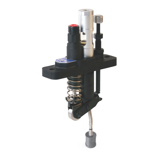
GBL 7500 Box Lubricator
Pump
GBL Shaft Rotation/Low Level
Alarm Pump
GBL 7500 Box Lubricator Pump: Fully enclosed, self-lubricating, precision, metering pump
capable of pumping small flows of either mineral or synthetic oil to machinery injection
points. For professional use only.
GBL Shaft Rotation/Low Level Alarm Pump: Fully enclosed, self-lubricating, precision,
alarm pump capable of sensing shaft rotation and oil low level. For professional use only.
3/16" models: 7500 psi (51.7 MPa, 517 bar) Maximum Working Pressure
1/4" models: 6000 psi (41.4 MPa, 414 bar) Maximum Working Pressure
3/8" models: 3500 psi (24.1 MPa, 241 bar) Maximum Working Pressure
Alarm Pump: 500 psi (3.4 MPa, 34.4 bar) Maximum Working Pressure
Important Safety Instructions
Read all warnings and instructions in this
manual. Save these instructions.
Models:
Suction Models
•
24J391 - 3/16"
•
24J392 - 1/4"
•
24J393 - 3/8"
Gravity Models
•
24J394 - 3/16"
•
24J395 - 1/4"
•
24J396 - 3/8"
Pressure Models
•
24J397 - 3/16"
•
24J398 - 1/4"
•
24J399 - 3/8"
Alarm Pump Model
•
24K466
3A2257F
Suction Model Shown
II 2G Ex hT6 Gb
EN
Advertisement
Table of Contents

Related Manuals for Graco GBL 7500


Summary of Contents for Graco GBL 7500
- Page 1 GBL Shaft Rotation/Low Level 3A2257F Alarm Pump GBL 7500 Box Lubricator Pump: Fully enclosed, self-lubricating, precision, metering pump capable of pumping small flows of either mineral or synthetic oil to machinery injection points. For professional use only. GBL Shaft Rotation/Low Level Alarm Pump: Fully enclosed, self-lubricating, precision, alarm pump capable of sensing shaft rotation and oil low level.
- Page 2 Warnings Warnings The following warnings are for the setup, use, grounding, maintenance, and repair of this equipment. The exclama- tion point symbol alerts you to a general warning and the hazard symbols refer to procedure-specific risks. When these symbols appear in the body of this manual, refer back to these Warnings. Product-specific hazard symbols and warnings not covered in this section may appear throughout the body of this manual where applicable.
- Page 3 Warnings WARNING EQUIPMENT MISUSE HAZARD Misuse can cause death or serious injury. • Do not operate the unit when fatigued or under the influence of drugs or alcohol. • Do not exceed the maximum working pressure or temperature rating of the lowest rated system compo- nent.
-
Page 4: Pressure Relief Procedure
Warnings Pressure Relief Procedure Follow the Pressure Relief Procedure whenever you see this symbol. This equipment stays pressurized until pressure is manually relieved. To help prevent serious injury from pressurized fluid, such as skin injection, splashing fluid and moving parts, follow the Pressure Relief Procedure when you stop pumping and before cleaning, checking or servicing the equipment. - Page 5 Setup Setup NOTICE Any pressure applied to the pump inlet has the potential to cause unrestricted flow from the pump outlet even in a pump that is at rest or adjusted for zero stroke. To pre- vent this from happening, install a check valve of a com- parable pressure rating at the pump outlet.
- Page 6 Setup Suction Fed Models (F . 4) Gravity Fed Models (F . 5) NOTE: In the following instructions, the fill line refers to the inlet line. 1. Remove and discard the sight well plug (1) and out- let plug (5). 2.
- Page 7 Setup Pressure Fed Models (F . 6) Alarm Pump Models (F . 7) NOTE: In the following instructions, the fill line refers to the inlet line. 1. Remove and discard the inlet plug (1) and outlet 1. Remove the sight well plug (1). plug (5).
-
Page 8: Adjusting The Pump
Setup Connecting Lube Lines to Pump: Suction, Alarm Models Only: Installing Pressure Gravity and Pressure Fed Pump Models Switch (see Alarm Pump, page 17) Only The pump’s check valve is monitored by a pressure switch. When fluid pressure reaches the check valve NOTE: The lube line refers to the outlet line supplying cracking pressure lubricant to the lubrication points. - Page 9 Setup 3. For Suction Fed and Gravity Fed models only: Calculating Output Capacity With the lubricator operating, count the drops from The number of drops observed falling in the sight well the drip tube (4) falling into the sight well (2) for one equals the amount of oil discharged by the pump.
-
Page 10: Specifications
Specifications Specifications Table 1 Drops per Stroke Table Section of Table Applies to Suction and Gravity Fed Models Only 1, 2 Piston Diameter Max Outlet Pressure† Drops/Stroke Cubic Inch/Stroke Cubic cm/Stroke inches Min* Min* Min* 3/16 4.76 7500 51.7 0.014 0.229 6.35 6000... -
Page 11: Troubleshooting
Troubleshooting Troubleshooting Problem Cause Solution Pump stroke is adjusted to zero. Adjust pump stroke for desired out- put. See page 8. Pump outlet is plugged. Clean/flush pump outlet. Pump does not flow Outlet check valve damaged. Replace pump. Pump inlet check ball and/or seat is damaged or worn. -
Page 12: Maintenance
Maintenance Maintenance 5. Torque sight well plug (1) to 35 + 5 in. lbs (3.95 + 0.6 N.m). Sight Well Runs Dry Should the oil level in the sight well (2) fall below the pump body surface: 1. Remove the sight well plug (1). 2. -
Page 13: Technical Data
Technical Data Technical Data Suction, Gravity Pressure Fed Box Lubricator Pump or Shaft Rotation Alarm Pump Maximum Working Pressure Metric All 3/16” Piston Models 7500 psi 51.7 MPa, 517 bar All 1/4” Piston Models 6000 psi 41.4 MPa, 414 bar All 3/8”... -
Page 14: Pump Dimensions
Technical Data Pump Dimensions Dimension Inches 3.10 76.20 1.97 50.04 0.50 12.70 Pump Min. 2.58 Pump Min. 65.53 Pump Max. 3.18 Pump Max.78.23 5.37 136.40 Min. 4.14 Min. 105.20 Max 4.90 Max 124.50 1.50 38.10 0.50 12.70 0.50 12.70 See Detail A 0.39 9.90 0.92... - Page 15 Technical Data Gravity Fed Inlet Outlet Outlet Pressure Fed Inlet 3A2257F...
- Page 16 Technical Data Suction Fed Outlet Inlet 3A2257F...
- Page 17 Technical Data Alarm Pump 1/4 NPT Sensor Output Return to Reservoir ti26974 Inlet 3A2257F...
-
Page 18: Graco Standard Warranty
With the exception of any special, extended, or limited warranty published by Graco, Graco will, for a period of twelve months from the date of sale, repair or replace any part of the equipment determined by Graco to be defective.
Need help?
Do you have a question about the GBL 7500 and is the answer not in the manual?
Questions and answers