Table of Contents

Related Manuals for Vintage Air Firebird 1969


Summary of Contents for Vintage Air Firebird 1969
- Page 1 an ISO 9001:2008 Registered Company 1969 Firebird without A/C Control Panel Conversion Kit 474164 18865 Goll St. San Antonio, TX 78266 ph: 210-654-7171 fax: 210-654-3113 904107 REV C 4/13/15, INST 69 FIREBIRD w/o AC CNTRL PNL PG 1 OF 17...
-
Page 2: Table Of Contents
Table of Contents 1. Cover 2. Table of Contents 3. Packing List/Parts Disclaimer 4. Removing OEM Control Panel Figures 1, 2 & 2a 5. Slide Pot Assembly Modifications & Slide Pot Aassembly Mounting Clamp Installation Figures 3 & 4 6. Dash/Floor/Defrost Slide Pot Assembly Installation Figures 5 &... - Page 3 .188 ID x .375 OD x .188 L Nylon Flat Washer ** Before beginning installation, open all packages and check contents of shipment. Please report any shortages directly to Vintage Air within 15 days. After 15 days, Vintage Air will not be responsible for missing or damaged items.
-
Page 4: Removing Oem Control Panel
Removing OEM Control Panel 1. Remove the (4) OEM mounting screws from behind dash (See Figure 1, below). 2. Remove the control panel. 3. Disconnect all cables and wires from control panel. 4. Remove brackets and blower switch from control panel. 5. - Page 5 Slide Pot Assembly Modifications 1. Locate the three slide pot assemblies. Using a pair of wire cutters, cut slide pot actuator rods as shown in Figure 3, below. Dash/Flr/Def Lever Cut at 3rd Hole Cut At Each Side (Remove Shaded Portion) of Hole as Shown Off/Hi Lever Slide Pot...
- Page 6 Dash/Floor/Defrost Slide Pot Assembly Installation 1. Install slide pot lever push rod onto Dash/Floor/Defrost lever as shown in Figure 5, below. 2. Secure the slide pot assembly to the control panel as shown in Figure 5a, below. 3. Since the slide pot assembly can slide back and forth in clamp before screw is tightened, position such that the flat part of the rod is as close to flush as possible with the end of the housing at the lever’s innermost position.
- Page 7 Dash/Floor/Defrost Slide Pot Assembly Installation (Cont.) 1. Locate the control panel wiring harness, and plug the corresponding wire into the correct slide pot assembly as shown in Figure 6, below. 2. Once the wire is correctly plugged into the slide pot assembly, secure wire to the slide pot assembly using tie wraps (supplied) (See Figure 6a, below).
-
Page 8: Off/Hi Slide Pot Assembly Installation
Off/Hi Slide Pot Assembly Installation 1. Install blower switch lever onto blower switch pivot bracket as shown in Figure 7, below. 2. Install blower switch pivot bracket assembly onto control panel as shown in Figure 7a, below. 3. Install slide pot assembly onto blower switch lever as shown in Figure 7b, below. 4. -
Page 9: Off/Hi Slide Pot Assembly Installation (Cont.)
Off/Hi Slide Pot Assembly Installation (Cont.) 1. Locate the control panel wiring harness, and plug the corresponding wire into the correct slide pot assembly as shown in Figure 8, below. 2. Once the wire is correctly plugged into the slide pot assembly, secure wire to the slide pot assembly using tie wraps (supplied) (See Figure 8a, below). -
Page 10: Cold/Hot Slide Pot Assembly Installation
Cold/Hot Slide Pot Assembly Installation 1. Install OEM Heat/Cool control lever, Heat/Cool control bracket and slide pot assembly as shown in Figure 9, below. 2. Secure the slide pot assembly to the control panel as shown in Figures 9a and 9b, below. 3. -
Page 11: Cold/Hot Slide Pot Assembly Installation (Cont.)
Cold/Hot Slide Pot Assembly Installation (Cont.) 1. Locate the control panel wire harness, and plug the corresponding wire into the correct slide pot assembly as shown in Figure 10, below. 2. Once the wire is correctly plugged into the slide pot assembly, secure wire to the slide pot assembly using tie wraps (supplied) (See Figure 10a, below). -
Page 12: Final Step
Final Steps 1. Using the supplied tie wraps, tie the wires and the unused wire to the control panel. Confirm that wires are secure and do not interfere with lever operation or slide pot assembly. 2. Install control panel from behind dash. NOTE: Make sure slide pot assemblies clear duct hose behind the left side of dash opening. -
Page 13: Control Panel Calibration Procedure
Control Panel Calibration Procedure On Vintage Air Gen IV systems using factory controls, it is necessary to calibrate the system to your specific control panel. This procedure ensures that the stroke of your control panel levers or knobs is translated into precise control of the fan speed, temperature blend and mode door position. -
Page 14: Control Panel Calibration Procedure (Cont.)
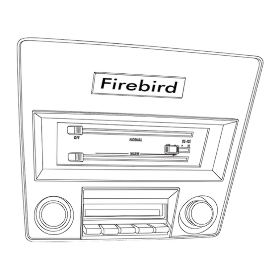
Control Panel Calibration Procedure (Cont.) 1. Turn on the ignition switch (Do not start the engine). NORMAL DE-ICE 2. Move the control levers/knobs to the position shown. WARM 3. Connect the white jumper wire to the gray program wire. Wait for the blower speed to change (Approximately 5 seconds). -
Page 15: Wiring Diagram
Wiring Diagram 232007-VUR AC ANNUNCIATOR BACKLIGHT POS BACKLIGHT NEG 5V-SW WHT/RED TEMP WIPER WHT/YEL MODE WIPER WHT/GRN FAN WIPER PRE-WIRED VIEWED FROM WIRE SIDE 232002-VUA GEN IV ECU GEN IV WIRING DIAGRAM (IF USED) REV D, 5/6/2014 TEMP MODE PROGRAM * DASH LAMP (IF USED) *** WIDE OPEN... -
Page 16: Operation Of Controls
Operation of Controls On Gen IV systems with three lever/knob controls, the temperature control toggles between heat and A/C operations. To activate A/C, move the temperature lever/knob all the way to cold and then back it off to the desired vent temperature. - Page 18 Packing List: 1969 Firebird Control Panel Conversion Kit (474164) Qty. Part No. Description 112002-SUA Slide Pot Assembly 232002-VUA Gen IV Universal Control Harness 491010-VUR Slide Pot Clamp 21301-VUP 4” Tie Wrap 231520 Ground Wire 644014 69 Firebird Blower Switch Pivot Bracket 644015 69 Firebird Blower Switch Lever 644016...
Need help?
Do you have a question about the Firebird 1969 and is the answer not in the manual?
Questions and answers