Table of Contents
Advertisement
Quick Links
Advertisement
Table of Contents

Related Manuals for CAB 5426C


Summary of Contents for CAB 5426C
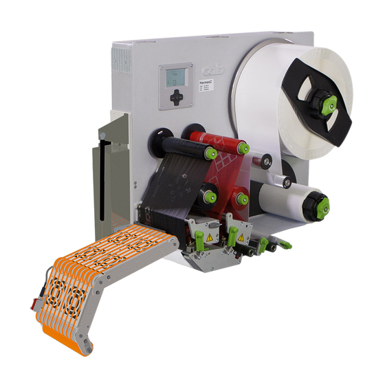
- Page 1 Service Manual 5426C Vacuum-Belt Applicator Made in Germany...
- Page 2 9003096 Copyright This documentation as well as translation hereof are property of cab Produkttechnik GmbH & Co. KG. The replication, conversion, duplication or divulgement of the whole manual or parts of it for other intentions than its original intended purpose demand the previous written authorization by cab.
-
Page 3: Table Of Contents
Table of Contents Introduction ............................4 Instructions ............................... 4 Intended Use ............................4 Safety Instruction ............................. 4 Safety Markings ............................5 Environment ............................. 5 Product Description ..........................6 Important Features ........................... 6 Technical Data ............................6 Device Overview ............................7 Contents of Delivery .......................... -
Page 4: Introduction
• The device applicator mounted on a cab printer of the Hermes+ series is intended exclusively for applying suitable materials that have been approved by the manufacturer. Any other use or use going beyond this shall be regarded as improper use. -
Page 5: Safety Markings
Introduction • Do not use the device close to high-voltage power lines. • Perform only those actions described in this operating manual. Work going beyond this may only be performed by trained personnel or service technicians. • Unauthorized interference with electronic modules or their software can cause malfunctions. Other unauthorized work on or modifications to the device can also endanger operational safety. -
Page 6: Product Description
Product Description Important Features • For operation in a system the I/O interface of the printer can be used. Technical Data Technical data Vacuum belt applicator 5426C Labeling On the surface, a cylinder and corner-wrap Dispensing direction left Label width 46-174... -
Page 7: Device Overview
Product Description Device Overview 1 Power supply cable of the printer 2 3-pole connector for sensor start 3 Power switch applicator 4 SUB-D 9 connector to the printer 5 Circuit board applicator control 6 Belt driven motor 7 Vacuum belt unit and ventilators 8 Sensor 9 Power supply with cover 10 Belt with motor shaft belt... -
Page 8: Contents Of Delivery
Product Description Contents of Delivery Fig. 3 Contents of delivery Mounted applicator (1) Screws for mounting the applicator to the printer (2) 4 x self-adhering cable guides Documentation Note! Please keep the original packaging in case the applicator needs to be transported or returned. Attention! The device and printing materials will be damaged by moisture and liquid. -
Page 9: Operation
Operation Standard Operation Check all external connections. Load the material. "Operator's Manual" Switch on the printer. Press the feed key of the printer. A synchronization feed is initiated. The processed labels need to be removed manually. After a few seconds the printer carries out a short backfeed to position the front edge of the next label at the printing line. -
Page 10: Power Supply Of The Device
Operation Power Supply of the Device Fig. 5 Power supply of the printer and the applicator Attention! When the power cable is connected the entire current flows through the power supply of the printer. The power switch of the applicator only affects the powers supply of the applicator. 1. Plug the power cable (2), as part of the contents of delivery, into the plug point of the applicator. 2. -
Page 11: Pivoting The Applicator
Operation Pivoting the Applicator Fig. 6 Pivoting the applicator Attention! Danger of injury to hands and fingers by the applicator! When releasing the snap lock keeping the applicator in place, it will drop due to its own weight. 1. To dismount the applicator (1), for cleaning or inserting material, pull the locking bolts (4) outward. 2. -
Page 12: Error Messages
Error Messages Error Messages of the Printer For detailed information about printer errors (e.g. 'Paper out', 'Ribbon out', etc.) Operator's manual of the printer Error treatment: Clear the error results. Press the feed key to synchronize the label feed and remove the peeled labels manually. ... -
Page 13: Installation
The values are listed in the setup protocol and delivered with the printer applicator system. The default factory values are: Connected to a cab Hermes+ printer, vertical Default material used for the setup: cab part No.: 5556472 54x35.5 Tools •... -
Page 14: Mounting And Dismounting The Applicator
Installation Mounting and Dismounting the Applicator Fig. 7 Mounting and dismounting the applicator Attention! Initiation, adjustments and changing of parts is to be performed by qualified service personnel only. Service Manual Applicator. Attention! Disconnect the printer from the power supply before mounting the applicator! Ensure the printer is standing securely in a stable position! To clean the applicator and printer it is sometimes necessary to pivot away or even dismount the applicator entirely from the printer. -
Page 15: External Start Sensor
Installation External Start Sensor The start signal to apply the label can originate from an external sensor connected to the 3 pole connector (1) connected directly to the applicator. Fig. 8 Start signal connector on the applicator Fig. 9 Examples of connections of start sensors The start of the printing job - print first label is still initiated over the I/O interface of the printer. Circuitry and programming of the connections is to be set as illustrated ... -
Page 16: Adjustments
Adjustments Note! The position of the applicator to the printer is predetermined by the factory and should not be altered to guarantee a reliable label take-over. Only change the angle of the applicator and the pressure of the pinch roller. Adjusting the Angle to the Printer max 20°... -
Page 17: Settings In The Configuration Of The Printer
Adjustments Settings in the Configuration of the Printer Label transport/reflex sensor Fig. 11 Waiting position of the label The operation mode "Blow" must be selected in the setup. Only once this is selected is it possible to change the parameter "Blow time". After detection of the label (1) by the reflex sensor (2) it will be transported further for a set time to reach the pinch roller (4). To change this value use the parameter: >... -
Page 18: Configuration
Configuration Quick Mode for Setting the Delay Times It is possible to set the transport speed of the label in four steps. By switching the parameter to Support del. off. Beside the standard method for the printer configuration there is a quick mode to adjust the delay times available. Note! The quick mode settings can be made during operation . The changes directly affect the current print job. 1. -
Page 19: Setting The Peel Position
Configuration Setting the Peel Position To optimize the transfer of the labels from the printer to the applicator there are two different parameters available for adjusting the peel position. Attention! First adjust the parameter "Peel Position" in the printer configuration. Then adjust the additional peel-off offset in the software. It is very important to follow this procedure for a seamless start after loading material and dealing with the treatment of error. -
Page 20: Test Operations
Test Operations Test Mode without a Print Job Warning! During operation movable parts are easily accessible. Particularly the transportation belts and fans pose a threat! Do not reach into these areas and keep things like long hair, loose clothes and jewelery away. Fig. -
Page 21: Replacing Components
Replacing Components Exchanging the Pinch Roller Fig. 13 Exchanging the pinch roller 1. Loosen screws (1). 2. Take out the pinch roller (2) with tubes (3) and the axle (4) out of the frame (5). 3. Pull out the axle shaft (4). 4. -
Page 22: Spare Parts
Spare Parts 10.1 Control Unit Part No. Description Serial No. Part No. Description Serial No. from from 5902838.001 Screw DIN7984-M3x6 5970246.001 Sensor Adapter 5948154.001 Cover 5555004.001 Cable USB 5900041.001 Distance Bolt M3x30 5551244.001 PCB Applicator Control 5918631.001 Power Supply 5901575.001 Cable Clamp 5905349.001 Switch 5906778.001 Locking Pin 5918052.001 Power Plug... -
Page 23: Vacuum-Belt Section 1
Spare Parts 10.2 Vacuum-belt Section 1 Part No. Description Serial No. Part No. Description Serial No. from from 5902565.001 Screw DIN7984-M4x10 5902304.001 Screw DIN7991-M4x6 5903033.001 Washer DIN125-A4.3 5905271.001 Grommet 8x3 5972593.001 Profile Axle 5902571.001 Screw DIN7984-M4x6 5901575.001 Cable Clamp 5972586.001 Base Plate 5902910.001 Screw DIN7984 M5x10 5972173.001 Fan 5902290.001 Screw DIN912-M5x35... -
Page 24: Vacuum-Belt Section 2
Spare Parts 10.3 Vacuum-belt Section 2 Part No. Description Serial No. Part No. Description Serial No. from from 5902565.001 Screw DIN7984-M4x10 5972584.001 Base Plate 5903033.001 Washer DIN125-A4.3 5971518.001 Cable Sensor 5902571.001 Screw DIN7984-M4x6 5972733.001 Holder 5902910.001 Screw DIN7984 M5x10 5902896.001 Screw DIN7984 M3x5 5902015.001 Screw DIN7991-M4x35 5918793.001 Sensor 5905271.001 Grommet 8x3... -
Page 25: Block Diagram
Block Diagram EEPROM SUB-D 9 Connection to the PCB applicator printer control 19/41 Label sensor 20/21 Motor belt driven CON 7 Distribution PCB fan CON 8 Fig. 17 Block diagram... -
Page 26: Index
Index Index Safety instruction ........4 Safety markings ........5 Block diagram ........25 Setting the peel position ....19 Signals ..........17 Spare parts ........22 Cleaning ..........9 Configuration parameters ....18 Standard operation ......9 Start sensor ........15 Contents of delivery ......8 Control unit ........22 Technical data........6 Test mode .........20 Delay times ........18 Tools ..........13...
Need help?
Do you have a question about the 5426C and is the answer not in the manual?
Questions and answers