Table of Contents
Advertisement
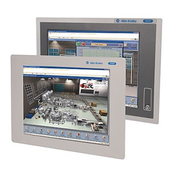
Integrated Display Computers
User Manual
Catalog Numbers
6181P-12NSXPH, 6181P-12NPXPH,
6181P-12TSXPH, 6181P-12TPXPH,
6181P-12TPXPHDC, 6181P-15NSXPH,
6181P-15NPXPH, 6181P-15TSXPH,
6181P-15TPXPH, 6181P-15TPXPHSS,
6181P-17NSXPH, 6181P-17NPXPH, 6181P-17TSXPH,
6181P-17TPXPH, 6181P-17TPXPHSS,
6181P-2PXPH, 6181P-2PXPH
Advertisement
Table of Contents
Troubleshooting

Subscribe to Our Youtube Channel
Related Manuals for Rockwell Automation Allen-Bradley 6181P-12NSXPH


Summary of Contents for Rockwell Automation Allen-Bradley 6181P-12NSXPH
- Page 1 Integrated Display Computers User Manual Catalog Numbers 6181P-12NSXPH, 6181P-12NPXPH, 6181P-12TSXPH, 6181P-12TPXPH, 6181P-12TPXPHDC, 6181P-15NSXPH, 6181P-15NPXPH, 6181P-15TSXPH, 6181P-15TPXPH, 6181P-15TPXPHSS, 6181P-17NSXPH, 6181P-17NPXPH, 6181P-17TSXPH, 6181P-17TPXPH, 6181P-17TPXPHSS, 6181P-2PXPH, 6181P-2PXPH...
- Page 2 No patent liability is assumed by Rockwell Automation, Inc. with respect to use of information, circuits, equipment, or software described in this manual. Reproduction of the contents of this manual, in whole or in part, without written permission of Rockwell Automation, Inc., is prohibited.
- Page 3 Summary of Changes The information below summarizes the changes made to this manual since the last revision. Revision bars, as shown in the margin, identify updated information. These are the changes for this version of the document. Topic Page Added revised wording for proper grounding. 17, 27 3Publication 6181P-UM001G-EN-P - July 2008...
- Page 4 Summary of Changes Publication 6181P-UM001G-EN-P - July 2008...
-
Page 5: Table Of Contents
Table of Contents Preface Intended Audience ....... . 7 Purpose of This Manual......7 Additional Resources. - Page 6 Table of Contents Install or Remove Add-In Cards ..... . 33 Replace the Floppy Drive (1500P and 1700P) ... . 40 Replace the Floppy or Optical Disc Drive (1200P) .
-
Page 7: Intended Audience
These publications are on the Accessories/Cloning CD, which ships with your computer. You can view or download publications at http://literature.rockwell.automation.com. To order paper copies of technical documentation, contact your local Rockwell Automation distributor or sales representative. Publication 6181P-UM001G-EN-P - July 2008... - Page 8 Appendix 2 Publication 6181P-UM001G-EN-P - July 2008...
-
Page 9: Chapter 1 Chapter Objectives
Chapter System Features Chapter Objectives This chapter provides an overview of the computers including: • Product options • Accessories • Operating systems • Features • Accessories • Parts List Overview The Integrated Display computers feature 12.1, 15, and 17-inch displays with a resistive touch screen option. When panel space is limited, the 12.1 inch model provides product information within a small space. -
Page 10: Product Options
Windows 2000. Catalog numbers ending in SS have a stainless steel bezel. Accessories and You can view a current list of accessories at the Rockwell Automation Allen-Bradley website http://www.ab.com/industrialcomputers. Replacement Parts Publication 6181P-UM001G-EN-P - July 2008... -
Page 11: Operating Systems
System Features Chapter 1 Operating Systems The computers are shipped with one of these operating systems: • Windows 2000 Professional, Service Pack 4 with Update Rollup 1 • Windows XP Professional, Service Pack 2b No operating system updates have been applied to the factory image beyond the service packs. -
Page 12: Features
Chapter 1 System Features Features The illustrations show the major features and controls of the computers. Top and Side View LCD Display 1500P and 1700P 1200P (with or without optional touchscreen) Floppy Disk Drive Bezel with Clip Mounting Optical Disc Drive Publication 6181P-UM001G-EN-P - July 2008... - Page 13 System Features Chapter 1 Bottom View 1200P COM1 Compact Flash Expansion Slot COM2 DC Power Input COM4 Power Switch Reset Button VGA Port Printer PCI Expansion Slot PS/2 Mouse Port 2 USB Ports PS/2 Keyboard Port Ethernet 10/100 Connector (RJ45) 1500P and 1700P Series A PCI Expansion Slot Printer 2...
-
Page 14: Before You Begin
Chapter 1 System Features Before You Begin Before unpacking the product, inspect the shipping carton for damage. If damage is visible, immediately contact the shipper and request assistance. Otherwise, proceed with unpacking. Keep the original packing material in case you need to return the product for repair or transport it to another location. -
Page 15: Chapter 2 Chapter Objective
European Union or EEA regions and has the CE Compliance mark. A copy of the Declaration of Conformity is available at the Rockwell Automation / Allen-Bradley website: www.ab.com/certification. This product is intended to operate in an industrial or control... -
Page 16: Environment And Enclosure Information
Chapter 2 Installation Environment and Enclosure Review the information on enclosures and environments before installing the product. Information Environment and Enclosure ATTENTION This equipment is intended for use in a Pollution Degree 2 industrial environment, in overvoltage Category II applications (as defined in IEC publication 60664-1), at altitudes up to 2000 meters (6562 feet) without derating. -
Page 17: Installation Considerations
Installation Chapter 2 Installation Considerations Follow these guidelines to make sure your product provides safe and reliable service. • The installation site must have sufficient power. To maintain an electrically safe installation, the product must ATTENTION be connected to Earth ground when installed. Follow the appropriate grounding requirements associated with your specific product type as described in this installation document. -
Page 18: Mounting Clearances
Chapter 2 Installation Mounting Clearances Allow adequate space around the computer for mounting, air flow, connections, and maintenance. Do not operate the computer in an enclosure by using the minimum clearances unless adequate ventilation or other cooling methods are used to lower the temperature within the enclosure. -
Page 19: Panel Mounting
Installation Chapter 2 Panel Mounting Install the computers by using mounting clips. Before installation, review: • Tools required. • Panel mounting guidelines. • Panel cutout dimensions. • Product dimensions. Tools Required The following tools are required for product installation: • Panel cutout tools •... - Page 20 Chapter 2 Installation Mount the Computer in a Panel Mounting clips secure the computer to the panel. Remove all electrical power from the panel before making ATTENTION cutout. Make sure the area around the panel cutout is clear. Take precautions so metal cuttings do not enter components already installed in panel.
-
Page 21: Bench Or Tabletop Mounting
Installation Chapter 2 6. Gradually tighten the clips, one at a time, around the bezel by using the specified sequence. The sequence begins with the center clips and continues to the corner clips. Repeat this process at least three times until the clips are hand-tight and the gasket is compressed uniformly against the panel. - Page 22 Chapter 2 Installation Mounting Guidelines Observe these guidelines when installing the computer on an arm: • The mounting surface must be strong enough to support both the computer and the mounting hardware. • The mounting arm must be strong enough to support the computer.
-
Page 23: Product Dimensions
Installation Chapter 2 Product Dimensions Product dimensions for each version of the computer are given in Dimensions are mm (in.). 1200P Integrated Display Computer 320 [12.60] 281 [11.079] 349 [13.75] 175.9 [6.93] 8.00 [0.31] 1200P Non-Display Computer 281 [11.079] 343 [13.51] 144.9 [5.70] 317.5 [12.51] 2 (.078) - Page 24 Chapter 2 Installation 1500P Integrated Display Computer 383.60 [15.10] 13.20 [0.52] 8.00 [0.31] 99.9 [3.93] 410.00 [16.14] 1700P Integrated Display Computer 422.00 [16.61] 14.0 [0.52] 101.6 [4.00] 8.00 [0.31] 452.00 [17.80] Publication 6181P-UM001G-EN-P - July 2008...
-
Page 25: Connect A Keyboard And Mouse
Installation Chapter 2 Connect a Keyboard and You can connect a keyboard to the PS/2 port on the bottom of the computer. You can connect both a keyboard and mouse to this port Mouse by using the Y-adapter cable that ships with the 6181P Series A computers. -
Page 26: Connect Ac Power
Chapter 2 Installation Connect AC Power A standard IEC 320 power cord provides power to the computer. The power supply input accepts 120/240V ac. The power supply is autoswitching. 1200P Only: You may need to remove the AC retainer clip before installing the unit in a panel cutout. -
Page 27: Connect The Dc Power
Installation Chapter 2 Connect the DC Power The 1200P computers with an integrated 24V DC power supply support these electrical ratings: • 18 to 32V DC (24V DC nominal) • 6.3 A at 24V DC The power supply is internally protected against reverse polarity. Use a Class 2/SELV (Safety Extra-Low Voltage) isolated and ATTENTION ungrounded power supply as input power to the computer. -
Page 28: Connect To The Network
Proper cable routing and power conditioning is required to ensure reliable Ethernet communication in industrial environments. Rockwell Automation recommends that you route all Ethernet cabling through dedicated metal conduits. Installing ferrite bead filters at cable ends may also improve reliability. -
Page 29: Chapter 3 Chapter Objective
Chapter Operation Chapter Objective This chapter covers the following topics: • General operating guidelines • Operator access to computer • Booting the system • Resetting the system • Installing drivers • Universal serial bus (USB) ports Operating Guidelines Follow these operating guidelines for your computer. •... -
Page 30: Start The System
Chapter 3 Operation Start the System Apply power to the system. The computer performs a Power On Self Test (POST). The processor board, memory, keyboard, and certain peripheral devices are tested. The system displays the progress of the POST and initialization of accessory devices. -
Page 31: Chapter 4 Chapter Objectives
• replace the floppy or optical disc drive (1200P). • replace the optical disk drive (1500P and 1700P). • replace the memory modules. Accessories and You can view a current list of accessories at the Rockwell Automation Allen-Bradley website http://www.ab.com/industrialcomputers. Replacement Parts Safety Precautions The computers contain line voltages. -
Page 32: Required Tools
Chapter 4 Replace System Components Required Tools Use a #2 Phillips screwdriver for all screws. Using the wrong size tool may cause damage to the screw head. Remove the Back Cover To maintain, install, or upgrade computer components, you must first remove the cover. -
Page 33: Install Or Remove Add-In Cards
Replace System Components Chapter 4 Install or Remove Add-In You can install PCI-compatible cards in the computer’s PCI slot. This section shows how to install and remove cards using the PCI Cards Expansion Slot Kit (6189V-2PCI15). The PCI Expansion Slot Kit is not required if you are installing IMPORTANT only one PCI card. - Page 34 Chapter 4 Replace System Components 4. Remove the one-slot riser board (two screws). PCI Riser Board 5. Add riser bracket (A) to the chassis by using six, M3x6 panhead screws. Riser Bracket (A) Publication 6181P-UM001G-EN-P - July 2008...
- Page 35 Replace System Components Chapter 4 6. Add riser bracket (B) to riser bracket (A) by using seven, M3x6 flat head screws. Riser Bracket (B) Riser Bracket (A) 7. Add the center support to the chassis by using three screws (two - M3x6 flat head, one - M3x6 pan head). Center Support Riser Bracket (B) Riser Bracket (A)
- Page 36 Chapter 4 Replace System Components 8. Add the riser board using the two screws from step 4. PCI Riser Board Center Support Riser Bracket (B) Riser Bracket (A) • The slot cover bracket attaches to the chassis with or without PCI cards.
- Page 37 Replace System Components Chapter 4 c. Fasten the slot cover bracket to the chassis by using four, M3x6 panhead screws. 9. If installing the expansion kit on a Series A computer, you may discard the replacement air duct and proceed to step 10. If installing the expansion kit on a Series B computer, you must replace the air duct that provides cooling air to the processor.
- Page 38 Chapter 4 Replace System Components 10. Reinstall the back cover over the chassis by using the screws from step 2. Publication 6181P-UM001G-EN-P - July 2008...
- Page 39 Replace System Components Chapter 4 Remove an Add-in Card Follow these steps to remove an add-in card. 1. Disconnect power from the computer. 2. Remove the back cover. 3. Remove the two screws securing the slot cover bracket to the chassis.
-
Page 40: Replace The Floppy Drive (1500P And 1700P)
Chapter 4 Replace System Components Replace the Floppy Drive Follow these precautions when working with the floppy drive. (1500P and 1700P) • Do not touch internal components unnecessarily. • Always handle the floppy drive by its metal frame. • Store the floppy drive in an anti-static bag when it is not installed. - Page 41 Replace System Components Chapter 4 4. Remove the screw(s) that fasten the floppy drive bracket to the chassis. Floppy Adapter 1500P and 1700P Floppy Drive Floppy Drive bracket 5. Slide the floppy drive and bracket and lift the floppy drive out door-first.
-
Page 42: Replace The Floppy Or Optical Disc Drive (1200P)
Chapter 4 Replace System Components Replace the Floppy or Follow these precautions when working with the floppy or optical disc drive. Optical Disc Drive (1200P) • Do not touch internal components unnecessarily. • Always handle the drive by its metal frame. •... - Page 43 Replace System Components Chapter 4 Remove the Drive Follow these steps to remove the drive. 1. Disconnect power from the computer. 2. Carefully separate the display head from the back chassis by removing the 12 perimeter screws. 3. Disconnect cables between the display and back chassis as necessary and set the back chassis aside.
- Page 44 Chapter 4 Replace System Components 8. Remove the screws securing the drive to the bay and carefully pull out the drive. 1200P Drive Adapter Spacer Drive Drive Brackets Install the Drive Follow these steps to install the drive. 1. Fasten the drive to the bay. 2.
-
Page 45: Replace The Optical Disc Drive (1500P And 1700P)
Replace System Components Chapter 4 Replace the Optical Disc Follow these precautions when working with the floppy or optical disk drive. Drive (1500P and 1700P) • Do not touch internal components unnecessarily. • Always handle the drive by its metal frame. •... - Page 46 Chapter 4 Replace System Components 7. Remove the two screws and spacers that fasten the adapter to the drive and remove the adapter from the drive. 1500P and 1700P Drive Adapter Spacer Drive Drive Brackets Install the Drive Follow these steps to install the drive. 1.
-
Page 47: Add Or Remove The Memory Module
The CPU board in the computer has two sockets. Each socket supports a Dual In-Line Memory Module (DIMM). Module For a current list of memory modules available for your computer, refer to the Rockwell Automation Allen-Bradley website http://www.ab.com/industrialcomputers. It is recommended that you use only qualified Allen-Bradley parts. - Page 48 Chapter 4 Replace System Components Publication 6181P-UM001G-EN-P - July 2008...
-
Page 49: Chapter 5 Chapter Objectives
Chapter System Troubleshooting Chapter Objectives This chapter describes the most common operating problems, the probable causes, and recommended corrective actions. It includes: • Hardware diagnostics • Troubleshooting procedures • Troubleshooting checklists Hardware Diagnostics The computer monitors: • Voltage ranges • Temperature requirements •... -
Page 50: Troubleshooting Procedure
Chapter 5 System Troubleshooting Troubleshooting Procedure Follow this procedure to identify and isolate a problem. 1. Shut down the computer’s operating system using the appropriate method for your operating system. 2. Disconnect the power to the computer. 3. Disconnect peripheral devices such as a printer or external drive. -
Page 51: Troubleshooting Checklists
System Troubleshooting Chapter 5 Troubleshooting Checklists Use the following checklists to test or verify items. Problems During Start-up • Are all connections secure? • Are the device drivers installed? • Are the jumpers on any add-in boards correctly positioned? • Is the hard drive formatted and recognized correctly in the BIOS? •... - Page 52 Chapter 5 System Troubleshooting Problems Running the New Software • Does the software have a hardware requirement that is not present? • Are you using an authorized copy of the software? Some copies of software will not work without proper activation. •...
-
Page 53: Chapter 6 Chapter Objectives
Chapter Maintenance Chapter Objectives This chapter provides information on how to: • clean the display. • replace the battery. • dispose of the backlight assembly. • ship or transport the computer. Clean the Display Use of abrasive cleansers or solvents may damage the display ATTENTION window. -
Page 54: Replace The Battery
Chapter 6 Maintenance Remove Paint and Grease Follow these steps to remove paint and grease. 1. Remove fresh paint splashes and grease before drying by rubbing lightly with isopropyl alcohol. 2. Perform a final wash with mild soap or detergent solution. 3. -
Page 55: Backlight Assembly Disposal
Doing so may cause damage to the product. You must uninstall the product and place in its original packing material before shipping. Rockwell Automation is not responsible for damage incurred to a product that is shipped or transported while installed in a machine, panel or rack. - Page 56 Chapter 6 Maintenance Publication 6181P-UM001G-EN-P - July 2008...
-
Page 57: Appendix A - Specifications
Appendix Specifications Display Type Active Matrix Color TFT Touchscreen (optional) Resistive antiglare Display size 1200P 12.1 in. 1500P 15 in. 1700P 17 in. Display area (WxH) 1200P 246 x 185 mm (9.7 x 7.3 in.) 1500P 305 x 229 mm (12 x 9 in.) 1700P 338 x 270 mm (13.3 x 10.7 in.) Resolution, native... - Page 58 Appendix A Specifications Electrical Input voltage, ac 90…264V AC autoranging Line frequency 47…63 Hz Ground leakage 1.0 uA max. at 1.5KV dc Power consumption, AC 1200P, 1500P, 1700P 150 VA (1.5 A @ 100V rms, 0.63A @ 240V rms) 1200P (6181P-2 non-display) 140 VA (1.4A @ 100V rms, 0.58A @ 240V rms) Input voltage, dc 1200P and 1200P (6181P-2 non-display) 18…32V dc...
- Page 59 Appendix Use the Touchscreen Computers with the touchscreen option are shipped with the touchscreen and touchscreen controller installed and connected. Touchscreen Serial Port The optional touchscreen controller connects internally to the COM3 serial port. The touchscreen is factory configured with the proper Usage COM3 and touchscreen driver settings, so no user configuration is required.
- Page 60 Appendix B Use the Touchscreen Calibrate the Touchscreen The touchscreen supplied with the computer is factory installed and calibrated. Follow these steps to recalibrate the touchscreen. 1. Run the touchscreen configuration utility through the PROGRAMS menu of the operating system. 2.
- Page 61 Appendix Upgrade to a New BIOS Introduction If a new BIOS is released to enhance the performance of your computer, or to correct a defect, you can download the BIOS and update your computer. Download the BIOS from the Rockwell Automation Allen-Bradley website at http://www.ab.com.
- Page 62 Appendix C Upgrade to a New BIOS Publication 6181P-UM001G-EN-P - July 2008...
- Page 63 Appendix Solid State Drive Introduction A reliable means of data storage is a concern in industrial applications with harsh requirements. Standard rotating media with its spinning platters and head arms (with temperature limitations) present obstacles to the reliable storage of data. Solid state drives (SSD) are a direct replacement for rotating hard drives on the IDE bus.
- Page 64 Appendix D Solid State Drive • The solid state drive installs on the computer’s IDE bus via the IDE ribbon cable. Pay close attention to connector alignment. Careless assembly can bend a pin or misalign the connectors, resulting in hardware damage. Configuration The solid state drive is configured for a single drive system, or as a master in a multiple drive system.
- Page 65 Solid State Drive Appendix D Operation The solid state drive appears to the system host as a standard rotating hard drive when powered up. The system host identifies the solid state drive during powerup and sets the IDE bus speed to reflect the drives capability:.
- Page 66 Appendix D Solid State Drive Wear leveling algorithms in flash memory drives offer an advantage to the overall throughput of the memory and the life expectancy of the drive. Wear leveling evenly distributes data that is written to memory across all free space on the drive. As one block of memory is written and filled, another is made available for the next data transfer.
- Page 67 Solid State Drive Appendix D Application Example Two The OS is updating its FAT table and root directory twice a second. This update requires one block of memory (128 K). Every write regardless of location writes to a single block. In this case, wear leveling is limited to 1 zone (512 blocks).
- Page 68 Appendix D Solid State Drive Publication 6181P-UM001G-EN-P - July 2008...
- Page 69 Index accessories 10 keyboard, connecting 25 add-in cards, installing and removing 32 maintenance back cover, removal 32 battery 54 cleaning display 53 battery replacement 54 mounting dimensions 23 boot the system 30 multilingual user interface 11 calibrating touchscreen 60 network connection 28 cover removal 32 cutout dimensions 19 operating guidelines 29...
- Page 70 Index environmental 57 check lists 51 mechanical 57 distorted or incorrect characters 52 system reset 30 problem after boot-up 51 problem during boot-up 51 problem running software 52 problem with add-in board 52 touchscreen problem with add-in card 52 calibrating 60 procedure 50 driver software 59 serial port 59...
- Page 72 New Product Satisfaction Return Rockwell Automation tests all of its products to ensure that they are fully operational when shipped from the manufacturing facility. However, if your product is not functioning and needs to be returned, follow these procedures.
Need help?
Do you have a question about the Allen-Bradley 6181P-12NSXPH and is the answer not in the manual?
Questions and answers