
Related Manuals for Festo 8079862


Summary of Contents for Festo 8079862
- Page 1 8079862 Filtration Learning System MPS PA Stations Operating instructions Festo Didactic 696684 en 09/2019...
- Page 2 09/2019 (V3.0.1) Authors: Jürgen Helmich, Frank Ebel Layout: Festo Didactic © Festo Didactic SE, Rechbergstraße 3, 73770 Denkendorf, Germany, 2019 +49 711 3467-0 www.festo-didactic.com +49 711 34754-88500 did@festo.com Reproduction, distribution and utilisation of this document, as well as the communication of its contents to others without explicit authorisation, is prohibited.
-
Page 3: Table Of Contents
8.2.2 Small parts included in the scope of delivery of the station ______________________________ 25 8.2.3 P&ID __________________________________________________________________________ 25 8.3 Function of the pressure control system _________________________________________________ 26 8.4 Proportional pressure regulator _______________________________________________________ 27 8.5 Pressure sensor with analog and switching signal_________________________________________ 27 © Festo Didactic 696684... - Page 4 10.4.3 Automatic operation, rinsing process ______________________________________________ 41 10.4.4 Manual mode _________________________________________________________________ 42 11 Commissioning _______________________________________________________________________ 43 11.1 Workstation ______________________________________________________________________ 44 11.2 Filling and emptying ________________________________________________________________ 44 11.3 Power supply _____________________________________________________________________ 45 11.4 Compressed air supply _____________________________________________________________ 45 © Festo Didactic 696684...
- Page 5 12.3 Error in the electrical system _________________________________________________________ 59 12.4 Mechanical error __________________________________________________________________ 60 12.5 Error due to parameterization ________________________________________________________ 60 13 Further information and updates ________________________________________________________ 61 14 Disposal ____________________________________________________________________________ 61 15 List of figures ________________________________________________________________________ 62 © Festo Didactic 696684...
- Page 6 Filtration Learning System © Festo Didactic 696684...
-
Page 7: General Requirements For Operating The Devices
Damaged devices must be banned from further use and removed from the laboratory or classroom. – Damaged connecting cables, pneumatic tubing and hydraulic hoses represent a safety risk and must be removed from the laboratory or classroom. © Festo Didactic 696684... -
Page 8: Pictograms
Strong optical radiation. Non-observance may result in severe personal injury. CAUTION ... indicates a possibly hazardous situation which may result in moderate or slight personal injury if not avoided. Hot surfaces. Non-observance may result in burns. © Festo Didactic 696684... - Page 9 Warning of laser radiation Warning of strong optical radiation Warning of hot surfaces Warning of crushing hazard Warning of drawing in due to rotating rollers Warning of loud noises Warning of lifting heavy loads Warning of accidental retraction © Festo Didactic 696684...
-
Page 10: Intended Use
Festo Didactic hereby excludes any and all liability for damages suffered by trainees, the training company and/or any third parties, which occur during use of the device in situations that serve any purpose other than training and/or vocational education, unless such damage has been caused by Festo Didactic due to malicious intent or gross negligence. -
Page 11: For Your Safety
Festo Didactic components and systems. In particular, the safety instructions must be adhered to by all persons who work with Festo Didactic components and systems. Furthermore, all pertinent accident prevention rules and regulations that are applicable at the respective place of use must be adhered to. -
Page 12: Dangers When Handling The Components And Systems
4.4 Dangers when handling the components and systems Festo Didactic systems and components are designed in accordance with the latest technology and recognized safety rules. However, life and limb of the user or third parties may be endangered and the machine or other property may be damaged during their use. -
Page 13: Work And Safety Instructions
Use a tool to operate the limit switches, for example a screwdriver. • Set all components up so that it’s easy to activate the switches and interrupters. • Follow the instructions regarding positioning of the components. © Festo Didactic 696684... -
Page 14: Electrical System
The power supply unit must be operated only with a power supply with a grounding conductor. • Establishing and disconnecting electrical connections – Electrical connections may be established only in the absence of voltage. – Electrical connections may be disconnected only in the absence of voltage. © Festo Didactic 696684... -
Page 15: Pneumatics
Do not disconnect tubing while under pressure. • Do not attempt to seal or plug pneumatic tubing or plug connectors with your hands or fingers. • Risk of injury when switching on compressed air! Cylinders can advance and retract automatically. © Festo Didactic 696684... -
Page 16: Process Technology
The liquid in the station can be drained by opening the drain valves! • No liquid should be left in the system for a long period of time, as bacteria such as Legionella can form in it. © Festo Didactic 696684... -
Page 17: Technical Data
Tank volume, waste water tank and process water tank Max. 10 l Dimensions of the station 700 mm x 700 mm x 1030 mm Dimensions of the profile plate 700 mm x 700 mm x 32 mm Weight, station 70 kg Subject to change © Festo Didactic 696684... -
Page 18: Pin Allocation Table
0 V power supply for outputs GND A Purple GND B 0 V power supply for inputs GND B 23+24 White-blue Note Cable jumpers are connected from emergency off to bit 1.5 on all preferred PLC versions. © Festo Didactic 696684... -
Page 19: Analog Terminal
24 V B 24 V power supply for inputs GND B 0 V power supply for inputs Pink 24 V A 24 V power supply for outputs GND A 0 V power supply for outputs Green © Festo Didactic 696684... -
Page 20: Control Panel
0 V power supply for inputs 23+24 White-blue Note Communication input I5 is used as an EMERGENCY-STOP signal input in PLC EduTrainers. The inputs and outputs of the control panel are located on the second byte of the EduTrainer. © Festo Didactic 696684... -
Page 21: Transport/Unpacking/Scope Of Delivery
The crate may only be transported with a suitable pallet jack or forklift. The crate must be secured against tipping over and falling. – Report transport damage without delay to the freight forwarder and Festo Didactic. 7.2 Unpacking Carefully remove the padding material from the crate when unpacking the station. When unpacking the system or station, make sure that none of its assemblies have been damaged. -
Page 22: Setup
1x I/O data cable with SysLink connectors to IEEE 488, crossed (order no. 167106) • 1x analog cable, parallel (order no. 529141) • Safety laboratory cable, 3 m (order no. 571817) • Control console with SIMATIC Touch Panel TP700 (order no. 8079869) © Festo Didactic 696684... -
Page 23: The Filtration Station
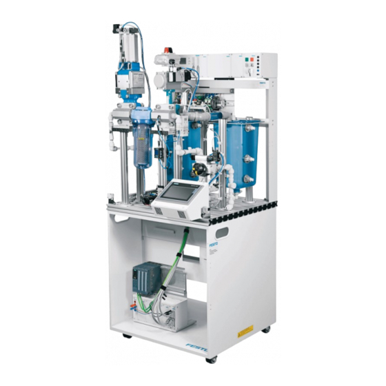
The finished process liquid can then be pumped to the downstream station with a pump. The following control functions can be edited: • Pressure section with PID controller (main function) Figure 2: Filtration station (similar to figure) © Festo Didactic 696684... -
Page 24: Main Components
L-plug connector 170701 17070x T-plug connector 170702 17070x Hand lever valve 170703 17070x Blanking plug 170705 17070x Push-in bracket 90° 690590 159410 Aluminum profile plate 700 x 700 159410 540691 Start-up valve with filter control valve 540691 © Festo Didactic 696684... -
Page 25: Small Parts Included In The Scope Of Delivery Of The Station
4 mm safety laboratory cables, 300 mm, blue 8092631 4 mm safety laboratory cables, 1500 mm, black 8092659 4 mm safety laboratory cables, 1500 mm, blue 8092658 8.2.3 P&ID Figure 3: P&ID in accordance to ISO10628 and EN 62424 © Festo Didactic 696684... -
Page 26: Function Of The Pressure Control System
A 0…10 V analog control signal determines the output value of the proportional pressure regulator with integrated control electronics as the manipulated variable. Backwashing acts as a disturbance variable if additional water is pumped back through the filter. © Festo Didactic 696684... -
Page 27: Proportional Pressure Regulator
For the switching output, PNP or NPN and normally open (NO) or normally closed (NC) can optionally be set. Through the IO-Link interface, process values can be read out and parameters changed and transmitted to additional devices. The voltage standard signal is connected to the analog terminal XD3 (UE1). © Festo Didactic 696684... -
Page 28: Stirrer
Warning of accidental retraction! There is a draw-in point at the rotating stirring staff or motor coupling and thus a risk of injury. Please do not touch the rotating parts during operation. © Festo Didactic 696684... -
Page 29: Pump
(2) and sensor box (5). The sensor box is used for electro-mechanical position feedback to the control and regulating equipment as well as for visual display for the operator. Figure 11: 3W ball valve unit (similar to figure) © Festo Didactic 696684... -
Page 30: Gate Valve And Butterfly Valve
Butterfly valve AF3 opened and gate valve SM2 closed (initial position) • Butterfly valve AF3 closed and gate valve SM2 opened Attention! Loud noises are generated when the drive units of the gate valve and butterfly valve are activated! © Festo Didactic 696684... -
Page 31: Level Monitoring
The lower proximity sensor indicates that the tank is empty (0 l). The upper proximity sensor indicates the minimum level of the tank, which is necessary to fully immerse the heater in the process liquid (min. 5 l). In the initial position, that is, with the tank full, both proximity sensors are actuated. © Festo Didactic 696684... -
Page 32: Float Switch, Lateral Installation
• Plastic tubing PUN 6x1, 5 m • T-plug connector for 6 mm tubing Figure 15: On-off valve with filter regulator Attention! Loud noises are generated when operating the service unit! © Festo Didactic 696684... -
Page 33: Electrical Connection Technology
10. Motor control: analog control of the motor of pump PL1 (0...10V corresponds to 0...24V). 11. Motor control: analog control of the motor of stirrer AG4 (0...10V corresponds to 0...24V). 12. Wiring terminals for overflow protection circuit © Festo Didactic 696684... -
Page 34: Mounting Frame
The mounting frame (1) of the MPS-PA station consists of a single-line ER frame for the connection board (2) and a 19″ frame (3) for 19″ mounting plates. The connection board is plugged into the ER frame. Figure 17: ER mounting frame (similar to figure) © Festo Didactic 696684... -
Page 35: 19" Frame
There is a risk of electric shock if used improperly! With the MPS PA 204 system, a 19″ EMERGENCY-STOP panel is added as an option to the 19″ frame of the Filtration and Reactor stations. © Festo Didactic 696684... -
Page 36: Plc Edutrainer Universal S7-1512C
The S7-1512C controller is connected to the automation network with a network cable (6 m). The sample project in combination with the TP700 Comfort control console enables the operation of the MPS PA station (see chapter 10.4 Sequence). © Festo Didactic 696684... -
Page 37: Control Console With Operator Unit Tp700 Comfort
EasyPort is used to connect a PC to actual hardware. Figure 20: EasyPort 19″ USB Optionally, the binary control of the process with the digital technology module or the GRAFCET can be created in combination with FluidSim. © Festo Didactic 696684... -
Page 38: Usb Device Server
The front side is equipped with mountings for panels. The trolley is supplied complete with twin castors. Figure 22: Trolley 700 Dimensions: • Height: 750 mm (including castors, to bottom edge of profile plate) • Width: 700 mm • Depth: 700 mm © Festo Didactic 696684... -
Page 39: Function
Communication between the MPS PA stations takes place via 4mm safety laboratory cables and the communication fields, as with MPS-D stations. Tank overflows in the Filtration station are monitored using float switches. The overflow protection is coupled to upstream and downstream stations using an optical transmitter and receiver. © Festo Didactic 696684... -
Page 40: Sequence Description
4. Filter until the waste water tank is empty (lower limit switch) or the process water tank is full (upper limit switch). 5. “Done” message 6. Continue with 1. The STOP function switches the actuators off at any time. © Festo Didactic 696684... -
Page 41: Automatic Mode With Downstream Station
9. “Done” message 10. Continue with 1. Recipe Pressure Time Recipe A 600 mbar 30 s Recipe B 800 mbar 50 s Recipe C 1000 mbar 90 s The STOP function switches the actuators off at any time. © Festo Didactic 696684... -
Page 42: Manual Mode
The sequence can be interrupted at any time by pressing the EMERGENCY-STOP button or by pressing the STOP button. • The following applies when several stations are combined: The individual stations are aligned in the order opposite the direction of material flow. © Festo Didactic 696684... -
Page 43: Commissioning
Filtration Learning System 11 Commissioning The stations of the MPS PAs are generally • Fully assembled • Individually adjusted and ready for use • Pre-commissioned • Tested Figure 24: Flow chart for commissioning an MPS PA station. © Festo Didactic 696684... -
Page 44: Workstation
11. Open the hand valve at the drain to drain the system. Note Always empty the station completely if it is not to be used for a long period of time. © Festo Didactic 696684... -
Page 45: Power Supply
Connect the digital I/Os of the EduTrainer (3/A) and the I/O terminal (5) XD1 of the station with I/O data cable SysLink (7) or check the connection. • Connect the digital I/Os of the EduTrainer (3/B) and control panel (4) with the I/O data cable SysLink (10) or check the connection. © Festo Didactic 696684... - Page 46 SysLink I/O data cable, parallel (034031) Analog cable, 15-pin, parallel (529141) Laboratory cable with safety laboratory sockets (red/blue) SysLink I/O data cables, parallel (034031) Figure 26: Cable connection MPS PA Station - EduTrainer Universal without power supply © Festo Didactic 696684...
-
Page 47: Cable Connections Between Control Console And Plc Edutrainer
The communication connections to the other stations must be established according to the following examples. The examples are general, but apply equally to all stations. Any deviations from this standard will be pointed out. Example of I/O push-in connectors between 19″ frames Figure 27: Communication connection between 19″ frames © Festo Didactic 696684... -
Page 48: Load Sample Project
8. Unarchive the file, e.g., MPS-PA_V2-4_CPU1512C_TP700_XXX.zap14 in directory ...\MPS-PA_Sources_V2-4\PLC&HMI\S7-1500_TP700 of the supplied CD-ROM. 9. Load the project into the PLC. Help can be found at Getting started. 10. Set the CPU switch to the RUN position © Festo Didactic 696684... -
Page 49: Starting The Sequence
4. Select a recipe in the process type. 5. Press the Start button. 6. The station starts the sequence. Notes • The sequence can be stopped at any time by pressing the emergency stop button or the STOP button. © Festo Didactic 696684... -
Page 50: Operation On The Control Console With Operator Unit Tp700 Comfort
2. Select one of the four operating modes: automatic, manual, controller configuration, or display of the trend. Note The actuators can be switched off at any time via the “STOP” button – automatic operation is ended. © Festo Didactic 696684... - Page 51 2. During the rinsing process: In “Conf. controller”, check the control parameters. 3. Press the “Start” button to start the recipe (see chapter 10.4 Sequence, recipe sequence). Figure 31: Automatic control screen, individual station © Festo Didactic 696684...
- Page 52 Figure 33: Automatic rinsing operating screen Note If tank VE1 is empty, the message “Filling tank VE1” appears. When the recipe is finished, you will receive the message "Recipe ready". 7. Use the "Back" button to return to the main menu. © Festo Didactic 696684...
- Page 53 Figure 35: Operating screen for manual operation – Reference value of the proportional pressure regulator 6. Set the control value directly or using the arrow buttons. Read the actual value of the flow rate on the display. 7. The “Back” button returns you to the Manual menu. © Festo Didactic 696684...
- Page 54 4. The manipulated variable, actual value, and setpoint value of the filling quantity are displayed in the curve diagram. Figure 37: “Trend” operator screen with the curve diagram 5. Use the "Back" button to return to the main menu. © Festo Didactic 696684...
-
Page 55: Actuation With Easyport 19
6 SysLink I/O data cable, parallel (034031) 7 Analog cable, 15-pin, parallel (529141) 8 Laboratory cable with safety laboratory sockets (red/blue) 9 Control panel with I/O data cable SysLink, parallel (034031) Figure 38: Cable connection MPS PA Station – EasyPort 19″ © Festo Didactic 696684... -
Page 56: Adjusting Sensors
The proximity sensor must be triggered by the liquid in the tank. If there is no liquid in the tank, no signal may be present. 5. Check the positioning and adjustment of the proximity sensor by repeated filling and emptying of the tank. © Festo Didactic 696684... -
Page 57: Float Switch, Lateral Installation
The float must move upward. 4. Check the positioning and adjustment of the sensor by repeated filling and emptying. Note Make sure that the float always moves freely and does not jam due to dirt. © Festo Didactic 696684... -
Page 58: Maintenance And Troubleshooting
Filtration Learning System 12 Maintenance and troubleshooting 12.1 Maintenance Festo Didactic systems and components are to a great extent maintenance free. The following components should be cleaned at regular intervals with a soft, lint-free cloth or brush: • The lenses on the optical sensors, the fiber optics and the reflectors •... -
Page 59: Error In The Piping System And Tanks
Visual inspection filter is not activated SysLink I/O terminal Signal statuses faulty Switching signals are not Slide switch is in Visual inspection displayed or are position NPN instead of with data sheet, observe displayed incorrectly representation © Festo Didactic 696684... -
Page 60: Mechanical Error
SmartBridge app sensor EasyPort Connection to EasyPort Connection cannot be Set the EasyPort at the EasyPort using the established address, e.g., 2, Address buttons © Festo Didactic 696684... -
Page 61: Further Information And Updates
Filtration Learning System 13 Further information and updates Further information and updates of the technical documentation for the Festo Didactic components and systems are available at the following website: www.ip.festo-didactic.com 14 Disposal Electronic waste contains reusable materials and must not be disposed of with household waste. -
Page 62: List Of Figures
_________________________________________________________ 53 Figure 36: Operator screen for controller configuration ____________________________________ 54 Figure 37: “Trend” operator screen with the curve diagram _________________________________ 54 Figure 38: Cable connection MPS PA Station – EasyPort 19″ ________________________________ 55 © Festo Didactic 696684... - Page 63 Filtration Learning System © Festo Didactic 696684...
- Page 64 Festo Didactic SE Rechbergstraße 3 73770 Denkendorf Germany +49 711 3467-0 www.festo-didactic.com +49 711 34754-88500 did@festo.com...
Need help?
Do you have a question about the 8079862 and is the answer not in the manual?
Questions and answers