Table of Contents
Advertisement
Quick Links
Advertisement
Table of Contents

Related Manuals for Lumel NMID30-2


Summary of Contents for Lumel NMID30-2
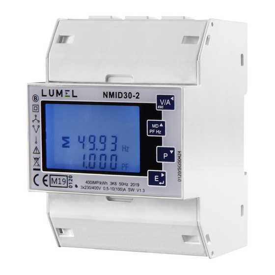
- Page 1 NMID30-2 1 and 3-phase energy meter 100 A (MID certi ed) User’s manual - MODBUS...
-
Page 2: Rs485 General Information
NMID30-2 _ Modbus 1. NMID30-2 Protocol Implementation Modbus Protocol Overview Input register 1.2.1 NMID30-2 Input Registers Modbus Protocol Holding Registers and Digital meter set up: 1.3.1 MODBUS Protocol Holding Register Parameters 2 RS485 General Information Half Duplex Connecting the Instruments... -
Page 3: Input Register
Modbus Protocol. It contains fields confirming the action taken, any data to be returned, and an error-checking field. If an error occurs in receipt of the message, the NMID30-2 will make no response. If the NMID30-2 is unable to perform the requested action, it will construct an error message and send it as the response. - Page 4 NMID30-2 _ Modbus 1.2.1 NMID30-2 Input Registers Address Parameter NMID30-2 Input Registers Input Register Modbus 3Ø 3Ø 1Ø (Register) Number Parameter Protocol Start Address Description Units 3W 2W Byte Byte 30001 Phase 1 line to neutral volts. Volts √ √...
- Page 5 NMID30-2 _ Modbus 30225 Neutral current. Amps √ 30235 Phase 1 L/N volts THD √ √ 30237 Phase 2 L/N volts THD √ 30239 Phase 3 L/N volts THD √ 30241 Phase 1 Current THD √ √ √ 30243 Phase 2 Current THD √...
- Page 6 NMID30-2 _ Modbus 1.3.1 MODBUS Protocol Holding Register Parameters Address Parameter Parameter Modbus Valid range Mode Register Number Protocol Start Address High Byte Byte 40001 Demand Time Read minutes into first demand calculation. When the Demand Time reaches the Demand Period then the demand values are valid.
-
Page 7: Half Duplex
NMID30-2 _ Modbus The Following information in this section relates to the NMID30-2 and is included to assist where a mixed network is implemented. RS485 or EIA (Electronic Industries Association) RS485 is a balanced line, half-duplex transmission system allowing transmission distances of up to 1.2 km. The... -
Page 8: Troubleshooting
NMID30-2 _ Modbus 2.3 A and B terminals The A and B connections to the NMID30-2 Digital meter products can be identified by the signals present on them whilst there is activity on the RS485 bus: 2.4 Troubleshooting Start with a simple network, one master and one slave. With the NMID30-2 Digital meter this is easily achieved as the network can be left intact whilst individual instruments are disconnected by removing the RS485 connection from the rear of the instrument. - Page 9 The MODBUS Protocol functions used by the NMID30-2 Digital meters copy 16 bit register values between master and slaves. However, the data used by the NMID30-2 Digital meter is in 32 bit IEEE 754 floating point format. Thus each instrument parameter is conceptually held in two adjacent MODBUS Protocol registers.
- Page 10 Following the last transmitted byte, a silent interval of at least 3.5 character times marks the end of the message. A new message can begin after this interval. In the NMID30-2 1000 and 2000, a silent interval of 60msec minimum is required in order to guarantee successful reception of the next request.
-
Page 11: Error Checking Methods
NMID30-2 _ Modbus 3.4 How Characters are Transmitted Serially When messages are transmitted on standard MODBUS Protocol serial networks each byte is sent in this order (left to right): Transmit Character = Start Bit + Data Byte + Parity Bit + 1 Stop Bit (11 bits total): Least Significant Bit (LSB) -
Page 12: Function Codes
NMID30-2 _ Modbus 3.6 Function Codes The function code part of a MODBUS Protocol message defines the action to be taken by the slave. The NMID30-2 Digital meter support the following function codes: Code MODBUS Protocol name Description Read Holding Registers... -
Page 13: Read Input Registers
3.8 MODBUS Protocol Commands supported The NMID30-2 Digital meters support the “Read Input Register” (3X registers), the “Read Holding Register” (4X registers) and the “Pre-set Multiple Registers” (write 4X registers) commands of the MODBUS Protocol RTU protocol. All values stored and returned are in floating point format to IEEE 754 with the most significant register first. -
Page 14: Exception Response
NMID30-2 _ Modbus “Starting Address” or the “Number of points” is odd then the query will fall in the middle of a floating point variable the product will return an error message. Field Name Example (Hex) Slave Address Function Byte Count... -
Page 15: Exception Codes
3.12 Diagnostics MODBUS Protocol code 08 provides a number of diagnostic sub-functions. Only the “Return Query Data” sub-function (sub-function 0) is supported on the NMID30-2 Digital meters. Example The following query will send a diagnostic “return query data” query with the data elements set to Hex(AA) and Hex(55) and will expect these to be returned in the...
Need help?
Do you have a question about the NMID30-2 and is the answer not in the manual?
Questions and answers