Table of Contents
Advertisement
Advertisement
Table of Contents

Related Manuals for TMT Automation PAPILLON 250


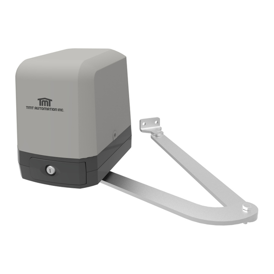
Summary of Contents for TMT Automation PAPILLON 250
- Page 1 PAPILLON 250 ARTICULATED ARM OPENERS 24V DC GEAR MOTOR USER MANUAL Transformer...
-
Page 2: Table Of Contents
INDEX 1.1 GENERAL PRECAUTION 1.2 INSTALLATION A. STANDARD INSTALLATION B. DIMENSION CHART C. Components of installation D. Installation of articulated arm opener E. Wire Connection F. Emergency Release G. Photocell Installation H. Green Box Installation I. Power Supply Connections CB19 Control Box LED Indication Transmitter Memorizing and Erasing Process System Learning Process... -
Page 3: General Precaution
1.1 GENERAL PRECAUTION: WARNING : This user manual is only for qualified technicians who is specialized in installations and automations. (1) All installations, electrical connections, adjustments and testing must be performed only after reading and understanding of all instructions carefully. (2) Before carrying out any installation or maintenance operation, disconnect the electrical power supply by turning off the magneto thermic switch connected upstream and apply the hazard area notice required by applicable regulations. -
Page 4: Installation
1.2 INSTALLATION STANDARD INSTALLATION 2x1.5 mm 4x0.5 mm RX - 4x0.5 mm TX - 4x0.5 mm 2x1.5 mm 2x1.5 mm 1. 24V DC blinker with integrated antenna 2. Push Button 3. Photocells 4. 24V DC articulated arm opener 5. TM3 Transmitter DIMENSION CHART Please comply with the measures shown on the chart for proper installation. -
Page 5: Components Of Installation
COMPONENTS OF INSTALLATION Straight arm 1 pce Curved arm 1 pce U-shaped fixing plate 1 pce Mechanical stopper 2 pcs Front-end fixing bracket 1 pce Screw 4 pcs Nut Ø10 2 pcs Screw 2 pcs Gasket 2 pcs Screw 2 pcs Spring washer 4 pcs Nut Ø8... -
Page 6: Wire Connection
3) Install the motor on the U-shaped fixing 4) After positioning the front of curved arm on the bottom of motor, plate with corresponding screws and nuts. release the motor and position the minor arm on the end of curved arm and mounting bracket with corresponding screws and nuts. -
Page 7: Emergency Release
EMERGENCY RELEASE 1) Insert the release key to the release slot 2) Turn the release key anti-clockwise 3) Pull out the release bar 4) Turn the release key clockwise to fix the release bar, the release bar has to be in pulled out position when turning the release key clockwise PHOTOCELL INSTALLATION The safety photocells are security devices for control automatic gates. -
Page 8: Green Box Installation
Figure 1(7) GREEN BOX INSTALLATION Green Box is for purpose when gate opener is in standby mode to allow it enter the power saving mode. Green Box AC out Cable AC in Installation manner: AC IN: connect the electricity AC OUT: connect the power of gate opener, and connect the transformer 5V CABLE: connect 3 pins white socket of control board Please make sure the switch of Green Box is off before proceeding the system learning and installation of device. -
Page 9: Cb19 Control Box
2. CB19 CONTROL BOX 1. Decide the installation position of control box first, it is suggested to be installed near the gate and should be protected from possible damage. Be aware of the motor cable length before deciding the installation position. 2. - Page 10 Figure 1(1) Transformer MOV1 LED Display DOWN RF-LEARN LED1 RF Learning LED2 Photocell 2 LED4 Photocell 1 LED3 Push botton or Key selector LED2 LED4 LED3 19 20 21 22 23 24 25 26 9 10 11 12 13 14 15 16 17 18 Lit+ Lit- Lat+...
- Page 11 Motor Only Figure 1(2) MOV1 LED2 LED4 LED3 9 10 11 12 13 14 15 16 17 18 19 20 21 22 23 24 25 26 Lit+ Lit- Lat+ Lat- Lmt1 Lmt2 DKey SKey Ph1 PhVcc PhVcc Lmt3 Lmt4 Transformer DOWN Motor1 Motor2...
-
Page 12: Led Indication
2.1 LED INDICATION DOWN LED1 System Learning: blue LED1 in receiver board blinks three times when learning is completed. LED2 RF : If the switch of the transmitter, key selector, or the push button is activated, LED2 will be on. RF-LEARN LED3 Photocells 1 : LED3 will be on when the first pair of the photocells are activated. -
Page 13: Gate Operation
2.4 GATE OPERATION Press the button “A” on the transmitter for dual-gate operation. Press the button “B” on the transmitter for single-gate operation in either single-gate or dual-gate installation. 2.5 GATE-MOVING LOGIC (A) In gate-opening phase: The gates stop if the transmitter/push button/key selector is activated, and close when the transmitter/push button/key selector is reactivated. -
Page 14: Photocell Adjustment
3.2 PHOTOCELL ADJUSTMENT The actions of the photocells safety edge loop detector when they detecting obstacles. 1. F9-1 Position of Gate When safety devices are activated Safety Device2 : Safety Device1 : Type of Safety Device Photocell-OPEN Photocell-CLOSE Open not allowed No effect FULLY CLOSED FULLY OPENED... -
Page 15: Trouble Shooting
4. TROUBLE SHOOTING Overheated Back-up Batteries Check the wiring connection of the batteries. The gate doesn’t move when pressing the 1. Check if LED3 or 4 is “OFF”. button of the transmitter 2. Check if the voltage of the batteries is upon 22V. 3. -
Page 16: Technical Feature
TECHNICAL FEATURE: Model PAPILLON 250 Motor 24Vdc motor Gear type Electromechanical worm gear Nominal thrust 1200N Maximum Gate Weight 250 kg per leaf Maximum Gate Length 2.5 meters per leaf Operating Temperature C~+50 Dimension 256 x 187 x 267mm Weight...
Need help?
Do you have a question about the PAPILLON 250 and is the answer not in the manual?
Questions and answers