Table of Contents
Advertisement
Advertisement
Table of Contents

Subscribe to Our Youtube Channel
Related Manuals for Kaba RAC 4XT


Summary of Contents for Kaba RAC 4XT
- Page 1 INSTALLATION GUIDE ILCO Remote Access Controller - RAC 4XT...
-
Page 2: Table Of Contents
4.1 Pre-Installation Procedures ..........9 Step 1: Identify a secure location for the RAC 4XT enclosure ......9 Step 2: Identify location(s) for card readers and peripherals . -
Page 3: Introduction And Disclaimers
CAUTION: Wear safety glasses when using any tools. Technical Support For technical assistance, call: (800) 906-4526 / (514) 340-9025 Visit the Kaba Support Website: www.kabalodgingsupport.com INSTALLATION GUIDE - REMOTE ACCESS CONTROLLER RAC 4XT • PK3191_10_14 Page 2... -
Page 4: Product Description
Standard Power Status LEDs feedback Standard Remote Unlock input Standard Request to Exit (REX) input Standard Battery Back-up Optional Relay Expansion Board with up to 8 relays Optional INSTALLATION GUIDE - REMOTE ACCESS CONTROLLER RAC 4XT • PK3191_10_14 Page 3... -
Page 5: Components
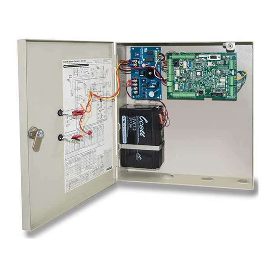
3 sides for routing of peripheral cables. (B) Power Supply: provides power required for operation of the controller PCB and all peripherals. (C) Controller Board (PCB): controls all INSTALLATION GUIDE - REMOTE ACCESS CONTROLLER RAC 4XT • PK3191_10_14 Page 4... -
Page 6: Card Readers
The RAC 4XT can also be used with the following types of peripherals: • Exit Devices • Motion Detectors • Panic Bars • Request to Exit (REX) button • Remote Unlock Button • Remote Programming Interface. INSTALLATION GUIDE - REMOTE ACCESS CONTROLLER RAC 4XT • PK3191_10_14 Page 5... -
Page 7: Checklist And Exploded Views
Power supply to LEDs Power supply to controller PCB Controller PCB jumpers (card (R) Front Desk Unit (FDU) reader type dependent) (R) ATLAS with Infra-red Programming Module (IPM) INSTALLATION GUIDE - REMOTE ACCESS CONTROLLER RAC 4XT • PK3191_10_14 Page 6... - Page 8 • Crimp tool – 18-22 AWG • Pliers • Wire cutter / stripper • FDU/ATLAS programmed “Test Lock” keycard • Hammer or rubber mallet • Awl or center punch INSTALLATION GUIDE - REMOTE ACCESS CONTROLLER RAC 4XT • PK3191_10_14 Page 7...
-
Page 9: Exploded View
3.2 Exploded View Figure 9 Hardware Bag Controller Box Power Adaptor North American International Peripherals / Optional Devices INSTALLATION GUIDE - REMOTE ACCESS CONTROLLER RAC 4XT • PK3191_10_14 Page 8... -
Page 10: System Installation Overview
Swipe, insert and extended range contactless Remove the selected knock-out(s) using card readers must be placed within 500 feet INSTALLATION GUIDE - REMOTE ACCESS CONTROLLER RAC 4XT • PK3191_10_14 Page 9... -
Page 11: Installation & Wiring Procedures
Table 1. Ensure that the correct wire color appropriate steps listed below, depending is attached to the correct terminal block on the type of card reader and configuration connection. being installed. INSTALLATION GUIDE - REMOTE ACCESS CONTROLLER RAC 4XT • PK3191_10_14 Page 10... - Page 12 (provided in the installation hardware bag) into the wall using a rubber mallet. Install the back plate onto the wall with the wood screws provided. INSTALLATION GUIDE - REMOTE ACCESS CONTROLLER RAC 4XT • PK3191_10_14 Page 11...
-
Page 13: Step 7: Connect Peripheral Wiring
PCB must be of the proper NOTE: Do not use the actual drawing from gauge and type as specified by the INSTALLATION GUIDE - REMOTE ACCESS CONTROLLER RAC 4XT • PK3191_10_14 Page 12... - Page 14 Always follow the locking device controller PCB connector J8, pins 3 & 4. manufacturer’s wiring recommendations INSTALLATION GUIDE - REMOTE ACCESS CONTROLLER RAC 4XT • PK3191_10_14 Page 13...
-
Page 15: Step 8: Relay Expansion Board Outputs Wiring
PCB as well as being indicated on the label on the inside of the door. Several Step 8: Relay Expansion Board outputs floors can be controlled by one relay (one wiring common area). INSTALLATION GUIDE - REMOTE ACCESS CONTROLLER RAC 4XT • PK3191_10_14 Page 14... -
Page 16: Step 9: Power Adaptor Connection
The relays in the RAC 4XT are UL rated and Figure 18 are capable of a maximum switching of 30 VDC @ 1A. For time duration of relay state change, please refer to the Access Delay Table in Annex A, Table 2. -
Page 17: Settings And Operation
Annex A, front of it to verify that the door unlocks. Table 2. 12. If the RAC 4XT is connected to a fire panel Follow the steps as per section 5.2 “Hotel verify that the electromagnetic lock or a ID Initialization”... -
Page 18: Programming And Auditing
Kaba Ilco Lodging Access Control Reference Manual. Figure 19 DB9 Cable RAC 4XT DB9 Cable DB9 Cable INSTALLATION GUIDE - REMOTE ACCESS CONTROLLER RAC 4XT • PK3191_10_14 Page 17... -
Page 19: Battery Back-Up Replacement
Figure 21 ensuring that the orientation and terminal polarities are as shown. In order, install the battery brackets, flat washer, split washers, and nuts. INSTALLATION GUIDE - REMOTE ACCESS CONTROLLER RAC 4XT • PK3191_10_14 Page 18... -
Page 20: Power Failure
PCB. If the LED is OFF use an initialization card with the reader and perform a time reset on the RAC 4XT as per the FDU or ATLAS manuals. NOTE: When the power to the RAC 4XT is... -
Page 21: Annexes
Please refer to ordering guide for current numbering. See detailed peripheral connections in Annex B. For latest part numbers please refer to the latest ordering guide or contact Kaba Customer Support. INSTALLATION GUIDE - REMOTE ACCESS CONTROLLER RAC 4XT • PK3191_10_14 Page 20... - Page 22 BLACK / WHITE XFMR-2 LOW BAT-1 YELLOW ( - ) XFMR-1 North America Battery Status DC OUT-2 ( + ) ( + ) XFMR-2 RED* ( + ) INSTALLATION GUIDE - REMOTE ACCESS CONTROLLER RAC 4XT • PK3191_10_14 Page 21...
-
Page 23: Annex B Peripheral Wiring Diagrams
Figure 3: Insert and Swipe Reader Wiring Insert Reader Swipe Reader Ingress 12V 1 RAC 4XT PCB 5V GND 12V Egress (RAC 4XT Only) Insert Reader Swipe Reader INSTALLATION GUIDE - REMOTE ACCESS CONTROLLER RAC 4XT • PK3191_10_14 Page 22... - Page 24 Bypass wire and connect J18 to the Fire Alarm panel as per Fire Alarm Panel Wiring diagram (see Annex B, Figure 10). In this case the Electric Strike MUST be powered from the RAC 4XT’s +12V output as shown in this diagram.
- Page 25 RAC 4XT’s +12V output as shown in this diagram. Figure 7: Externally Powered Locking Device Wiring (+12 volts or + 24 volts) IMPORTANT: Kaba does not provide Technical or Field Support on 3 party locking devices. Please contact the device manufacturer for assistance on installation or functional issues.
- Page 26 Black Wire Red Wire 5V GND 12V Power Supply NOTE: If the Egress reader is not used on RAC 4XT, the motion detector can be powered from J14, pin 3 (12V) Motion and J14, pin 2 (GND). Detector INSTALLATION GUIDE - REMOTE ACCESS CONTROLLER RAC 4XT • PK3191_10_14...
- Page 27 Normally Closed dry contact output. Note 2: If the Fire Alarm Panel connection is not required, place a jumper wire between pin 3 and 4 of J18. INSTALLATION GUIDE - REMOTE ACCESS CONTROLLER RAC 4XT • PK3191_10_14 Page 26...
- Page 28 Connections (See Note 4) Note 1: Make sure all the wiring is complete, including the ribbon cable, before applying power to the RAC 4XT to ensure proper Relay Expansion Board functionality. Note 2: The relay outputs are “fail safe”. Accordingly, they are energized in their normal state and the relay status LED is ON. Upon power failure, or when the Fire alarm input is activated (when connected to a Fire Alarm panel), the relay state will change and access will be automatically granted.
-
Page 29: Annex C Protection From Electromagnetic Interference
6.0 Annex C Protection from Electromagnetic Interference As per any other electronic equipment, the RAC 4XT can be affected by electromagnetic inter- ference caused by industrial electrical equipment such as elevator motors. To prevent the unit from operational instability such as "freezing" or losing programming, shei- lded cables should be used and connections made as per the diagram below. -
Page 30: Annex D Quick Troubleshooting Guide
- If qualified, with a multi-meter verify that 24 VAC (North American power adaptor) or 24 VDC (international power adaptor) is present across power supply terminal block XFMR_1 and XFMR_2 as per Annex A, Table 5.. INSTALLATION GUIDE - REMOTE ACCESS CONTROLLER RAC 4XT • PK3191_10_14 Page 29... - Page 31 Symptom Action Request to Exit does not work - Verify that the REX LED (D33) on the RAC 4XT controller turns on when the button is pressed. If not, verify the wiring to the Request to Exit button. Remote Unlock does not work - Verify that the Remote Unlock LED (D36) on the RAC 4XT controller turns on when the button is pressed.
- Page 32 • Verify that the Request to Exit or Remote Unlock activation unlocks the door. • Verify that the card is encoded properly. • Verify that the RAC 4XT is not in Lockout mode. • Verify that the RAC 4XT is programmed properly.
- Page 33 - Verify that the relays are not bypassed (the bypass switches SW1 and SW4 on the Relay Expansion Board should be off). - Verify that the RAC 4XT is not in passage mode. Relay Expansion Board relays do not - Activate the manual bypass switches SW1 and...
- Page 34 - If the RAC 4XT is not initialized (Initialization LED, D41, is OFF): • Follow the instructions in Section 5.2 "Hotel ID Initialization". - If the RAC 4XT was already initialized, it may need to be re-initialized: • Follow the instructions in section 5.3 “Hotel ID Re-Initialization”.
-
Page 35: Annex E Drilling Templates For Swipe Card Reader
6.0 Annex E Drilling Templates for Swipe Card Reader INSTALLATION GUIDE - REMOTE ACCESS CONTROLLER RAC 4XT • PK3191_10_14 Page 34... - Page 36 6.0 Annex E Drilling Templates for Swipe Card Reader NOTE: If swipe reader is model R71-2XX with 4 mounting holes, please contact Technical Support) INSTALLATION GUIDE - REMOTE ACCESS CONTROLLER RAC 4XT • PK3191_10_14 Page 35...
-
Page 37: Annex F Drilling Template For Insert Card Reader
6.0 Annex F Drilling Template for Insert Card Reader INSTALLATION GUIDE - REMOTE ACCESS CONTROLLER RAC 4XT • PK3191_10_14 Page 36... -
Page 38: Annex G Drilling Template For Contactless Card Reader
6.0 Annex G Drilling Template for Contactless Card Reader INSTALLATION GUIDE - REMOTE ACCESS CONTROLLER RAC 4XT • PK3191_10_14 Page 37... -
Page 39: Annex H Drilling Template For Contactless Card Reader
7301, Décarie Boul. Montréal, Qc, Canada H4P 2G7 www.kaba-ilco.com DATE UNE VERSION FRANCAISE DE CE DOCUMENT SHEET 21AU14 EST DISPONIBLE SUR DEMANDE. DT-514800 REV-1 1 OF 1 15174 INSTALLATION GUIDE - REMOTE ACCESS CONTROLLER RAC 4XT • PK3191_10_14 Page 38... - Page 40 Kaba Ilco Inc. 7301 Boul. Décarie Montréal (QC) H4P 2G7 Customer Service and Technical Support: T: 1.877.468.3555 F: 514.735.6589 General Information: www.kabalodging.com Online Consumable Orders: www.ilcostore.com To access all of our easy steps, please visit our Support Website: www.kabalodgingsupport.com...
Need help?
Do you have a question about the RAC 4XT and is the answer not in the manual?
Questions and answers
need part # for a battery back up
The provided context does not contain the part number for a battery backup for the Kaba RAC 4XT.
This answer is automatically generated