Table of Contents
Advertisement
Quick Links
EM542S Digital Stepper Drive User Manual
User Manual
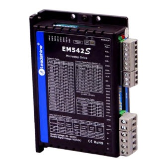
EM542S
Digital Microstep Drive
Revision 3.0
©2019 Leadshine Technology Co., Ltd.
Address: Floor 11, Block A3, Nanshan iPark, Xueyuan Avenue 1001, Shenzhen, Guangdong, 518055, China
Tel: (86)755-26409254
Fax: (86)755-26402718
Web:
Sales:
www.leadshine.com
sales@leadshine.com
Support:
tech@leadshine.com
Advertisement
Table of Contents

Related Manuals for Leadshine EM542S


Summary of Contents for Leadshine EM542S
- Page 1 EM542S Digital Stepper Drive User Manual User Manual EM542S Digital Microstep Drive Revision 3.0 ©2019 Leadshine Technology Co., Ltd. Address: Floor 11, Block A3, Nanshan iPark, Xueyuan Avenue 1001, Shenzhen, Guangdong, 518055, China Tel: (86)755-26409254 Fax: (86)755-26402718 Web: Sales: www.leadshine.com sales@leadshine.com...
- Page 2 Strictly adhere to the technical information regarding installation requirements. This manual is not for use or disclosure outside of Leadshine except under permission. All rights are reserved. No part of this manual shall be reproduced, stored in retrieval form, or transmitted by any means, electronic, mechanical, photocopying, recording, or otherwise without approval from Leadshine.
-
Page 3: Table Of Contents
EM542S Digital Stepper Drive User Manual Table of Contents 1.Introduction..................................1 1.1 Features...................................1 1.2 Applications................................1 2.Specifications..................................2 2.1 Electrical Specifications............................2 2.2 Environment................................2 2.3 Mechanical Specifications............................2 2.4 Elimination of Heat..............................3 3. Connection Pin Assignments and LED Indication...................... 3 3.1 P1 - Control Connector Configurations........................3 3.2 P2 - Fault and Brake Output Connector......................... -
Page 4: Introduction
(10-25%), quicker response time, control command smoothing, easy self-test, etc. The EM542S is able to power 2 phase (1.8°) and 4 phase (0.9°) stepper motors smoothly with very low motor heating & noise. It can take 20-50VDC supply voltage and output 0.5 to 4.2A current. All the micro step and output current configurations can be easily done via built in DIP switches. -
Page 5: Specifications
EM542S Digital Stepper Drive User Manual 2. Specifications 2.1 Electrical Specifications Parameters Typical Unit Output Current 4.2 (3.0 RMS) Supply Voltage 24 - 48 Logic signal current Pulse input frequency Minimal pulse width μs Minimal direction setup μs Isolation resistance MΩ... -
Page 6: Elimination Of Heat
Connectors, DIP switches, and LED locations The EM542S has 5 connectors P1, P2, P3, P4 and P5, 3 DIP switches S1, S2 and S3. P1 is for control signal connections, P2 is for fault output, P3 is for power connection, P4 is for motor connection and P5 is for fine tuning. -
Page 7: P2 - Fault And Brake Output Connector
3.6 Status LED Lights There are two LED lights for EM542S. The GREEN one is the power indicator which should be always on in normal circumstance. The RED one is a drive status indication light, which will be OFF while working normally but ON and flash 1 or 2 times in a 3-second period in the case of enabled over-current or over-voltage protection. -
Page 8: Control Signal And Fault Output
When over voltage or over current protection happens, EM542S red status LED light will blink and the impedance state between ALM and COM- will change (from low to high or high to low depending on configuration) and can thus be detected. -
Page 9: Stepper Motor Connections
Figure 7 Brake Output Connection 5. Stepper Motor Connections EM542S can drive 2-phase and 4-phase bipolar hybrid stepper motors with 4, 6, or 8 leads, Leadshine also offers easy-to-use and good-performance motors with 4-lead that have been tested with EM542S: (http://www.leadshine.com/series.aspx?type=products&category=stepper-products&producttype=stepper-motors&subt... -
Page 10: 8-Lead Motor Connection
Although setting the drive output current to 1.4 times of driven motor phase current will get the most torque, it is suggested to set an EM542S’s output current (peak of sinusoidal) to no more than 1.2 times the stepper motor’s phase current to prevent overheating. Refer to the figure 12 for how to connect an 8-lead stepper motor for parallel connection. -
Page 11: Power Supply Sharing
EM542S Digital Stepper Drive User Manual 6.2 Power Supply Sharing Multiple EM542S drives can share the same power supply, if that power supply has enough capacity. To avoid cross interference, connect each EM542S DIRECTLY to that shared power supply separately instead of connecting those power connectors of drives in daisy-chain connection. -
Page 12: Idle Current Configuration (Sw4)
7.2 Idle Current Configuration (SW4) The SW4 of an EM542S is used to set output current percentage when motor is standstill. Idle current percentage will be set to 50% at OFF position, and 90% at ON position. When the driven stepper motor is idle (no movement) for 0.4 second, the output current of EM542S will be automatically reduced to the configured percentage. -
Page 13: Smoothing Filter Time Configuration (Sw9-10)
(SW11) EM542S can configure itself with the best match to the driven stepper motor. This feature may need to be disabled for some applications or when it is used to drive a specially designed stepper motor. To do that, set the DIP switch SW11 to ON position and the drive will be set to its default settings. -
Page 14: Wiring Notes
It is better to separate them by at least 10 cm; otherwise the disturbing signals generated by motor will easily disturb pulse direction signals, causing motor position error, system instability and other failures. If only one power supply serves multiple EM542S drives, separately connecting the drives to the power supply is ... -
Page 15: Protection Functions
11. Protection Functions EM542S incorporates are built with over-voltage and over-current error protections. When it is under error protection, the red LED light will blink for 1 or 2 or 4 times in a period of 3 seconds. If fault output connection is connected, the impedance mode between ALM+ and ALM- will be changed (See “Fault Output Configuration”... -
Page 16: Troubleshooting
EM542S Digital Stepper Drive User Manual 12. Troubleshooting In the event that your drive doesn’t operate properly, the first step is to identify whether the problem is electrical or mechanical in nature. The next step is to isolate the system component that is causing the problem. As part of this process you may have to disconnect the individual components that make up your system and verify that they operate independently. -
Page 17: Warranty
Leadshine Technology Co., Ltd. warrants its products against defects in materials and workmanship for a period of 12 months from shipment out of factory. During the warranty period, Leadshine will either, at its option, repair or replace products which proved to be defective.
Need help?
Do you have a question about the EM542S and is the answer not in the manual?
Questions and answers