Table of Contents
Advertisement
Quick Links
Advertisement
Table of Contents

Related Manuals for Cisco ASR 907


Summary of Contents for Cisco ASR 907
- Page 1 Cisco ASR 907 Router Hardware Installation Guide First Published: 2015-10-01 Last Modified: 2019-07-31 Americas Headquarters Cisco Systems, Inc. 170 West Tasman Drive San Jose, CA 95134-1706 http://www.cisco.com Tel: 408 526-4000 800 553-NETS (6387) Fax: 408 527-0883...
- Page 2 © 2015–2019 Cisco Systems, Inc. All rights reserved.
- Page 3 8-Port 1 Gigabit Ethernet RJ45 Interface Module (A900-IMA8T) 1-Port 10 Gigabit Ethernet XFP Interface Module (A900-IMA1X) 8-port 10 Gigabit Ethernet Interface Module (8x10GE) (A900-IMA8Z) 8-Port 1 Gigabit Ethernet SFP with 1-Port 10 Gigabit Ethernet Combination Interface Module (A900-IMA8S1Z) Cisco ASR 907 Router Hardware Installation Guide...
-
Page 4: Table Of Contents
Safety Guidelines for Personal Safety and Equipment Protection Safety Precautions for Module Installation and Removal Safety with Electricity Power Supply Considerations Preventing ESD Damage Site Planning General Precautions Site Planning Checklist Site Selection Guidelines Cisco ASR 907 Router Hardware Installation Guide... - Page 5 Installing Plenum A907-F2B-AIR-U Assembly and Chassis in the Rack Installing the Chassis in the Air Plenum Attaching the Cable Management Brackets Installing the Chassis Ground Connection Installing the Fan Tray Removing and Replacing the Dust Filter Removing the Dust Filter Cisco ASR 907 Router Hardware Installation Guide...
- Page 6 Activating the AC Power Supply Removing and Replacing the AC Power Supply Installing Dust Caps Connecting the Cisco ASR 907 Router to the Network Connecting Console Cables Connecting to the Serial Port using Microsoft Windows Connecting to the Console Port using Mac OS X...
- Page 7 Connector and Cable Specifications C H A P T E R 4 Cisco Router Initial Configuration Checking Conditions Prior to System Startup Powering Up the Cisco ASR 907 Router Verifying the Front Panel LEDs Cisco ASR 907 Router Hardware Installation Guide...
- Page 8 Contents Verifying the Hardware Configuration Checking Hardware and Software Compatibility Configuring the Cisco ASR 907 Router at Startup Using the Console Interface Configuring Global Parameters Checking the Running Configuration Settings Saving the Running Configuration to NVRAM Safely Powering Off the Cisco ASR 907 Router...
- Page 9 OC-3 Interface Module LEDs T1/E1 Interface Module LEDs Serial Interface Module LEDs Power Supply LEDs Fan Tray LEDs Alarm Conditions A P P E N D I X A Site Log and Manufactures Manufactures Cisco ASR 907 Router Hardware Installation Guide...
- Page 10 Contents Cisco ASR 907 Router Hardware Installation Guide...
- Page 11 C H A P T E R Cisco ASR 907 Router Overview The Cisco ASR 907 Router seven-rack unit router that belongs to the Cisco ASR90x family of routers. This router complements Cisco’s offerings for IP RAN solutions for the GSM, UMTS, LTE and CDMA. Given its form-factor, interface types and GigabitEthernet density the Cisco ASR 907 Router can also be positioned as a Carrier Ethernet aggregation platform.
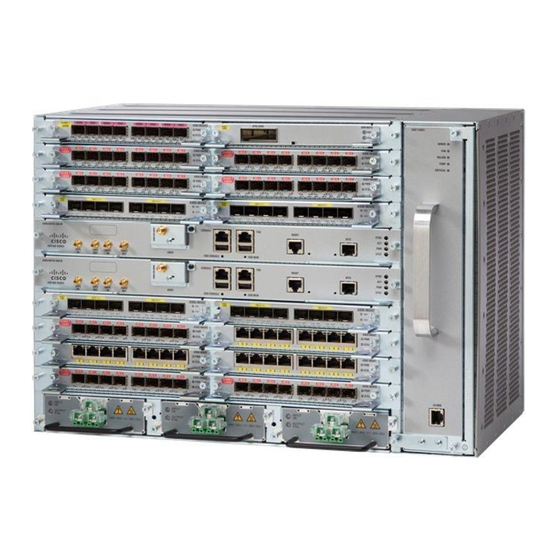
- Page 12 • Timing support for receipt and distribution of network frequency and time including SyncE, BITS, 1PPS/10MHz I/O, IEEE 1588-2008, and NTP. • Support for ENET OAM. • T1/E1 line protection compliant with NEBS GR-1089. The following image illustrates the Cisco ASR 907 Router chassis design. Cisco ASR 907 Router Hardware Installation Guide...
- Page 13 Redundant power units (two DC power units are shown). Fan tray Fan tray filter System Specifications The table below summarizes the system specifications and environmental requirements for the Cisco ASR 907 Router. Table 1: Cisco ASR 907 Router System Specifications Dimensions (Height x Width x Depth) 12.224 inches x 17.426 inches x 9.33 inches...
- Page 14 Cisco ASR 907 Router Overview GNSS Module (A900-CM-GNSS) Operating Temperature The Cisco ASR 907 Router (with industrial temperature optics) supports the following temperature ranges at 1800 m operating altitude: • -40º C to 65º C Nonoperating Temperature -40º F to 158º F (-40º C to +70º C) storage temperature Operating Humidity 5–95% operating non-condensing relative humidity...
- Page 15 • Use a passive splitter if more than one GNSS modules are fed from a single antenna. Power Supply Features The Cisco ASR 907 Router supports 1200W DC/AC power supplies on all the three PSU slots. The AC and DC power supplies support: •...
- Page 16 If you install a redundant power supply on the Cisco ASR 907 Router, we recommend that you connect each power supply to a separate input power source in order to ensure that the router maintains power in the event of a power interruption caused by an electrical failure, a wiring fault, or a tripped circuit breaker.
- Page 17 RSP Modules The Cisco ASR 907 Router is designed to use up to two RSP modules to handle the data plane, network timing, and control plane functionalities for the router. The RSP configuration allows you to use Cisco IOS software to control chassis management, redundancy, external management, and system status indications on the router.
- Page 18 LED indicators Supported RSPs Effective Cisco IOS-XE Release 3.16, the Cisco ASR 907 Router supports the following RSP: • A900-RSP3C-400-W—Provides 8 GB of SDRAM, 20 Mb of TCAM memory on every ASIC. The RSP does not provide external network interfaces for user traffic. All network interfaces are provided through separate IMs.
- Page 19 • If the module does not come up, perform a reload of the router. Supported Interface Modules Note There are certain restrictions in using the interface modules on different slots in the chassis. Contact Cisco Sales and Support for the valid combinations. Cisco ASR 907 Router Hardware Installation Guide...
- Page 20 Module 1-port OC-192 or 8-Port Low Rate CEM A900-IMA8S1Z-CX 3,4,7,8,11,12 (10 G Mode) Interface Module 0,1,2,5,6,9,10,13,14,15 (5 G Mode) 48-port T1/E1 Interface module A900-IMA48D-C 2,3,4,5,6,7,8,9,10,11,12,13,14,15 48-port T3/E3 Interface module A900-IMA48T-C 2,3,4,5,6,7,8,9,10,11,12,13,14,15 A900-IMA3G-IMSG 3,5,7,9,11,13,15 Cisco ASR 907 Router Hardware Installation Guide...
- Page 21 These slots are supported on 10G or 20G mode. These slots are supported on 10G or 20G mode, only if the adjacent odd slots are empty. These slots are supported on 10G mode. Cisco ASR 907 Router Hardware Installation Guide...
- Page 22 RSP Redundancy The Cisco ASR 907 Router chassis includes two RSP slots to allow for redundant RSPs. When the router uses redundant RSPs, one RSP operates in the active mode and the other operates in the hot standby mode. Removal or failure of the active RSP results in an automatic switchover to the standby RSP.
- Page 23 • 10GE port on Phase2 IMs—Supports LAN, WAN, OTU1e/2/2e modes of operation • 2X40 GE interface module—Supports QSFP mode • T1/E1 ports with integrated inter-office surge protection—Supports TDM channelized, PWE3 processing and ATM IMA bundles Cisco ASR 907 Router Hardware Installation Guide...
- Page 24 • T3/E3 ports - Supports TDM channelized, PWE3 Processing • OC3/OC12/OC48/OC192 - Supports TDM channelized, PWE3 Processing Note For information about supported interface modules, see the data sheet for the Cisco ASR 900 Series Aggregation Services Routers. For more information about installing, see the Installing an Interface Module.
- Page 25 Cisco ASR 907 Router Overview 8-Port 1 Gigabit Ethernet RJ45 Interface Module (A900-IMA8T) For information on supported SFP modules, see Cisco ASR 900 Series Aggregation Services Routers Data Sheet. 8-Port 1 Gigabit Ethernet RJ45 Interface Module (A900-IMA8T) The 8-port 1 Gigabit Ethernet RJ45 interface module provides eight Gigabit Ethernet copper ports. The figure below shows the interface module.
- Page 26 Cisco ASR 907 Router Overview 8-port 10 Gigabit Ethernet Interface Module (8x10GE) (A900-IMA8Z) For information on supported SFP modules, see Cisco ASR 900 Series Aggregation Services Routers Data Sheet. 8-port 10 Gigabit Ethernet Interface Module (8x10GE) (A900-IMA8Z) Figure 6: 8-port 10 Gigabit Ethernet Interface Module The high density 8-port 10 Gigabit Ethernet interface module supports eight 10 Gigabit Ethernet ports using SFP+ transceivers cages on the faceplate.
-
Page 27: (A900-Ima8T1Z)
Figure 7: 8-port 1 GE SFP + 1-port 10 GE SFP+ Interface Module For information on supported SFP modules, see Cisco ASR 900 Series Aggregation Services Routers Data Sheet. 8-Port 1 Gigabit Ethernet + 1-Port 10 Gigabit Ethernet SFP+ Combination Interface Module... -
Page 28: 2-Port 10 Gigabit Ethernet Sfp+ Interface Module (A900-Ima2Z)
The 2-port 10 Gigabit Ethernet interface module provides a dual port supporting a 10 Gigabit Ethernet SFP+ and XFP module. Figure 9: 2-port10 Gigabit Ethernet Interface Module For information on supported SFP modules, see Cisco ASR 900 Series Aggregation Services Routers Data Sheet. Cisco ASR 907 Router Hardware Installation Guide... -
Page 29: 1-Port 100 Gigabit Ethernet Interface Module (1X100Ge) (A900-Ima1C)
Figure 10: 1-port 100 Gigabit Ethernet Interface Module The 1-port 100 Gigabit Ethernet interface module supports one CPAK optics port. For information on supported CPAK modules, see Cisco ASR 900 Series Aggregation Services Routers Data Sheet. 2-Port 100 Gigabit Ethernet Interface Module (2X100GE) (N560-IMA2C) The 2-port 100 Gigabit Ethernet Interface Module (N560-IMA2C) design supports only one 100G QSFP28 optics on Port 0. -
Page 30: 2-Port 40 Gigabit Ethernet Qsfp Interface Module (2X40Ge) (A900-Ima2F)
Figure 12: 2-port 40 Gigabit Ethernet Interface Module For information on supported SFP modules, see Cisco ASR 900 Series Aggregation Services Routers Data Sheet. 8/16-Port 1 Gigabit Ethernet (SFP / SFP) + 1-port 10 Gigabit Ethernet (SFP+) / 2-port 1 Gigabit Ethernet... -
Page 31: 16-Port T1/E1 Interface Module (A900-Ima16D)
Gigabit Ethernet (1 X SFP) / 2-port Gigabit Ethernet (1 X CSFP) and 16-port Gigabit Ethernet (8 X CSFP) / 8-port Gigabit Ethernet (8 X SFP) Interface Module chapter of the Cisco ASR 900 Router Series Configuration Guide, Cisco IOS XE Everest 16.6.1. -
Page 32: 32-Port T1/E1 Interface Module (A900-Ima32D)
It is supported on the A900-RSP2A-64 module in slots 3, 4 and 5, and on the A900-RSP2A-128 on all slots. The 32-port T1/E1 interface module requires the use of a patch panel to provide RJ48 or BNC connectors. Figure 15: 32-portT1/E1 Interface Module Cisco ASR 907 Router Hardware Installation Guide... -
Page 33: 8-Port T1/E1 Interface Module (A900-Ima8D)
The 48-port T1/E1 interface module provides connectivity for up to 48 T1/E1 ports through 3 high-density connectors on the front panel (as shown in figure 48-port T1/E1 Faceplate). Each port supports 16 TX and RX ports. Cisco ASR 907 Router Hardware Installation Guide... -
Page 34: 48-Port T3/E3 Cem Interface Module (A900-Ima48T-C)
The 48-port T3/E3 interface module provides connectivity for up to 48 T3/E3 ports through 3 high-density connectors on the front panel (see the figure below). Each port supports 16 TX and RX ports. Figure 19: 48 x T3/E3 Interface Module Figure 20: 48-port T3/E3 Faceplate Cisco ASR 907 Router Hardware Installation Guide... -
Page 35: 1-Port Oc-48/Stm-16 Or 4-Port Oc-12/Oc-3 / Stm-1/Stm-4 + 12-Port T1/E1 + 4-Port
If OC48 is enabled, then the remaining 3 ports are disabled. Figure 21: A900-IMA3G-IMSG Gigabit Ethernet Interface Module For information on supported SFP modules, see Cisco ASR 900 Series Aggregation Services Routers Data Sheet. 1-Port OC-192 or 8-Port Low Rate CEM Interface Module (10G HO / 10G LO) (A900-IMA8S1Z-CX) The 1-port OC-192 interface module with 8-port low rate CEM interface module is a high density combination interface module. - Page 36 • 1 Gigabit Ethernet port configuration is supported on all ports simultaneously Note 1 Gigabit Ethernet port configuration is not supported. • Seamless migration from SONET to 1 Gigabit Ethernet interfaces is supported on all SFP ports Cisco ASR 907 Router Hardware Installation Guide...
-
Page 37: (A900-Ima1Z8S-Cxms)
The ASR 900 Combo 8-Port SFP GE and 1-Port 10GE With CEM/iMSG, 20G Interface Module is a cost-effective interface module (IM) that supports CEM and Multiservice Gateway features on the OCn interfaces. Note The Multiservice Gateway features are not supported on this IM on Cisco IOS XE Release 16.12.1. Cisco ASR 907 Router Hardware Installation Guide... - Page 38 • On the port capable of OC-192 speed, lower speed such as, OC-3, OC-12, or OC-48 are not supported. • Separate licenses are required for every OC-3, OC-12 ports, OC-48, and OC-192 ports. Cisco ASR 907 Router Hardware Installation Guide...
-
Page 39: Temperature Sensor
Temperature Sensor Temperature Sensor The Cisco ASR 907 Router has a temperature sensor to detect ambient overtemperature conditions inside the chassis. The operating temperature range is between –40 C to +65 C. Temperatures outside this range are reported to the processor as an interrupt, and the software takes action to generate the appropriate alarms. - Page 40 Cisco ASR 907 Router Overview Regulatory Compliance Cisco ASR 907 Router Hardware Installation Guide...
-
Page 41: Preparing For Installation
C H A P T E R Preparing for Installation The following sections describe how to prepare for the installation of the Cisco ASR 907 Router at your site: • Safety Guidelines, on page 31 • Site Planning, on page 39 •... - Page 42 This is a class A product. In a domestic environment this product may cause radio interference in which case the user may be required to take adequate measures. Statement 340 Warning This equipment is in compliance with the essential requirements and other relevant provisions of Directive 1999/5/EC. Cisco ASR 907 Router Hardware Installation Guide...
-
Page 43: Safety Guidelines For Personal Safety And Equipment Protection
Invisible laser radiation may be emitted from disconnected fibers or connectors. Do not stare into beams or view directly with optical instruments. Statement 1051 Warning Class 1M laser radiation when open. Do not view directly with optical instruments. Statement 1053 Cisco ASR 907 Router Hardware Installation Guide... -
Page 44: Safety With Electricity
8 AWG minimum with a 40 A circuit breaker. Statement 1005 Warning This product relies on the building’s installation for short-circuit (overcurrent) protection. For an AC installation, ensure that the branch circuit breaker is rated a maximum 20A. Cisco ASR 907 Router Hardware Installation Guide... - Page 45 This equipment must be grounded. Never defeat the ground conductor or operate the equipment in the absence of a suitably installed ground conductor. Contact the appropriate electrical inspection authority or an electrician if you are uncertain that suitable grounding is available. Statement 1024 Cisco ASR 907 Router Hardware Installation Guide...
- Page 46 When installing or replacing the unit, the ground connection must always be made first and disconnected last. Statement 1046 Warning Never install an AC power module and a DC power module in the same chassis. Statement 1050 Cisco ASR 907 Router Hardware Installation Guide...
- Page 47 • If possible, send another person to get medical aid. Otherwise, determine the condition of the victim, and then call for help. • Determine whether the person needs rescue breathing or external cardiac compressions; then take appropriate action. Cisco ASR 907 Router Hardware Installation Guide...
-
Page 48: Power Supply Considerations
• Never attempt to remove the printed circuit board from the metal carrier. Note For the safety of your equipment, periodically check the resistance value of the antistatic wrist strap. It should be between 1 and 10 Mohm. Cisco ASR 907 Router Hardware Installation Guide... -
Page 49: Site Planning
• The site meets the environmental requirements. • The site’s air conditioning system can compensate for the heat dissipation of the Cisco ASR 907 Router. • The floor space that the Cisco ASR 907 Router occupies can support the weight of the system. -
Page 50: Environmental Requirements
0, slot 1 and so on. Air Flow Guidelines Cool air is circulated through the Cisco ASR 907 Router by a fan tray located along the right side of the router. Air flow is side-to-side, right to left, as shown in the figure below. - Page 51 Preparing for Installation Air Flow Guidelines Figure 25: Cisco ASR 907 Router Chassis Air Flow To ensure adequate airflow, it is recommended that you maintain a minimum clearance distance always, as mentioned in the following figure. Cisco ASR 907 Router Hardware Installation Guide...
- Page 52 Preparing for Installation Air Flow Guidelines Figure 26: Front View of Cisco A907-F2B-AIR Clearance Cisco ASR 907 Router Hardware Installation Guide...
- Page 53 Preparing for Installation Air Flow Guidelines Figure 27: Side View of Cisco A907-F2B-AIR Clearance The fan trays maintain acceptable operating temperatures for the internal components by drawing in cool air through the vents, and circulating the air through the chassis.
-
Page 54: Air Flow Guidelines For Enclosed Rack Installation
Air Flow Guidelines for Enclosed Rack Installation To install a Cisco ASR 907 Router in a 4-post enclosed cabinet, the front and rear doors of the cabinet must be removed or be perforated with a minimum of 65% open area (70% for 800mm racks). - Page 55 Site Power Guidelines Note The Cisco ASR 907 Router installation must comply with all the applicable codes and is approved for use with copper conductors only. The ground bond fastening hardware should be of compatible material and preclude loosening, deterioration, and electrochemical corrosion of hardware and joined material. Attachment of the chassis ground to a central office or other interior ground system must be made with a 6 AWG gauge wire, copper ground conductor at a minimum.
-
Page 56: Electrical Circuit Requirements
The Cisco ASR 907 Routers can be powered by a DC source or an AC source. Ensure that equipment grounding is present and observe the power strip ratings. Make sure that the total ampere rating of all products plugged into the power strip does not exceed 80% of the rating. -
Page 57: Asynchronous Terminal Connections
The typical sources of EMI are equipment power cords and power service cables from electric utility companies. Strong EMI can destroy the signal drivers and receivers in the Cisco ASR 907 Router and even create an electrical hazard by causing power surges through the power lines into installed equipment. These problems are rare but could be catastrophic. -
Page 58: Precautions For Rack-Mounting
• Do not step on or stand on any component or system when servicing other systems or components in a rack. • When mounting the Cisco ASR 907 Router in a partially filled rack, load the rack from the bottom to the top, with the heaviest component at the bottom of the rack. -
Page 59: Installation Checklist
Locating for Safety If the Cisco ASR 907 Router is the heaviest or the only piece of equipment in the rack, consider installing it at or near the bottom to ensure that the rack’s center of gravity is as low as possible. -
Page 60: Creating A Site Log
Log as well as a sample Site Log that can be used to make copies. Receiving the Cisco ASR 907 Router Each Cisco ASR 907 Router chassis is shipped in a container. See the figure below. Cisco ASR 907 Router Hardware Installation Guide... -
Page 61: Chassis-Lifting Guidelines
Preparing for Installation Chassis-Lifting Guidelines Figure 28: Cisco ASR 907 Router Packaged for Shipping Pallet Corrugated spacer Pellet deck board Carton Bottom foam Edge protector Top foam Tape Tray — Chassis-Lifting Guidelines The chassis is not intended to be moved frequently. Before you install the system, ensure that your site is properly prepared so that you can avoid having to move the chassis later to accommodate power sources and network connections. -
Page 62: Tools And Equipment
• Crimping tool as specified by the ground lug manufacturer • 8 AWG copper wire for the power cord • Wire-stripping tools for stripping both 6 AWG and 8 AWG wire • Tape measure and level Cisco ASR 907 Router Hardware Installation Guide... -
Page 63: Unpacking And Verifying The Shipped Contents
Use the table below to check the contents of the Cisco ASR 907 Router shipping container. Do not discard the shipping container. You will need the container if you move or ship the Cisco ASR 907 Router in the future. - Page 64 • T1/E1 cable connector (required only for T1/E1 interface modules) Note Most Cisco documentation is available online. Documentation that is shipped with your Cisco ASR 907 Router includes the Regulatory Compliance and Safety Information for the Cisco ASR 900 Series Aggregation Service Router document, and the Cisco ASR 900 Series Aggregation Service Router Documentation Roadmap that contains information about the various documents that are available online and the links to them.
-
Page 65: Installing The Cisco Asr 907 Router
• Unpacking and inspecting the Cisco ASR 907 Router • Gathering the tools and test equipment required to properly install the Cisco ASR 907 Router For more instructions on how to prepare for the installation of the Cisco ASR 907 Router, see Preparing for Installation. -
Page 66: Installing The Router Chassis In The Rack
Remove the rack-mount brackets from the accessory kit and position them beside the router chassis. The figure below shows how to attach the brackets on the Cisco ASR 907 Router for a 19-inch EIA rack and 300 mm ETSI Cabinet. - Page 67 Do not use interface module and power supply ejector handles to lift the chassis; using the handles Caution to lift the chassis can deform or damage the handles. Installing the Chassis to support the Japanese JIS Rack Standard. Figure 30: Installing the Chassis in a 19-inch EIA Rack Cisco ASR 907 Router Hardware Installation Guide...
- Page 68 Installing the Cisco ASR 907 Router Installing the Router Chassis in the Rack Figure 31: Installing the Chassis to support the Japanese JIS Rack Standard Cisco ASR 907 Router Hardware Installation Guide...
-
Page 69: Installing Plenum A907-F2B-Air-U Assembly And Chassis In The Rack
Installing Plenum A907-F2B-AIR-U Assembly and Chassis in the Rack Procedure Step 1 Position the air baffle and the side plate to the plenum. Secure the air baffle using a maximum torque of 11.5 in.-lb (1.3 N-m). See figure below. Cisco ASR 907 Router Hardware Installation Guide... - Page 70 Position the plenum assembly to the rack and secure the cable brackets to the rack using a torque of 11.5 in.-lb (1.3 N-m). See figure below. For a 19-inch rack installation, the rack has to have a flat post. Note Cisco ASR 907 Router Hardware Installation Guide...
- Page 71 Installing Plenum A907-F2B-AIR-U Assembly and Chassis in the Rack Figure 34: Plenum Assembly to Rack Step 3 Repeat Step-1 and Step-2 to complete the plenum assembly on the other side of the plenum base. Cisco ASR 907 Router Hardware Installation Guide...
- Page 72 Position the plenum assembly to the rack and secure the cable brackets to the rack using a torque of 11.5 in.-lb (1.3 N-m). See figure below. For a 19-inch rack installation, the rack has to have a flat post. Note Cisco ASR 907 Router Hardware Installation Guide...
- Page 73 Installing the Cisco ASR 907 Router Installing Plenum A907-F2B-AIR-U Assembly and Chassis in the Rack Figure 37: Plenum Assembly to 21-inch Rack Cisco ASR 907 Router Hardware Installation Guide...
-
Page 74: Installing The Chassis In The Air Plenum
Position the chassis so that the rear of the chassis is at the front of the plenum. See the figure below. Step 2 Slide the chassis into the plenum so that the front of the chassis is in flush with the mounting rails and brackets. Cisco ASR 907 Router Hardware Installation Guide... -
Page 75: Attaching The Cable Management Brackets
Installing the Cisco ASR 907 Router Attaching the Cable Management Brackets Figure 39: Cisco ASR 907 Chassis with Air Plenum Cisco ASR 907 router Air plenum Attaching the Cable Management Brackets The router supports the following brackets: • A907-CABLE-GUIDE—This guide helps in routing the cables from the interface modules; therefore enabling a proper cable bending radius. -
Page 76: Installing The Chassis Ground Connection
(1.12 N-m). Installing the Chassis Ground Connection Before you connect the power or turn on the power to the Cisco ASR 907 Router, you must provide an adequate chassis ground (earth) connection to your router. This section describes how to ground the Cisco ASR 907 Router chassis. The router provides two locations for attaching a 2-hole grounding lug according to the rack-mounting brackets you use to install the router. - Page 77 • Wire-stripping tools appropriate to the wire you are using Caution Before making connections to the Cisco ASR 907 Router, ensure that you disconnect the power at the circuit breaker. Otherwise, severe injury to you or damage to the router may occur.
- Page 78 This unit is to be installed in a restrictive access location and must be permanently grounded to minimum 6 AWG copper ground wire. Perform the following procedure to ground the Cisco ASR 907 Router using a 2-hole lug and the corresponding mounting point. Most carriers require a minimum 6 AWG ground connection. Verify your carrier’s requirements for the ground connection.
-
Page 79: Installing The Fan Tray
Connect the other end of the ground wire to a suitable grounding point at your site. Installing the Fan Tray The fan tray is a modular unit that provides cooling to the Cisco ASR 907 Router. Note Do not introduce body parts or objects in the fan tray slot when installing or removing the fan tray module. -
Page 80: Removing And Replacing The Dust Filter
Secure the fan tray to the chassis using the attached captive installation screws. The recommended maximum torque is 5.5 in.-lb (.62 N-m). This completes the procedure for installing or replacing the fan tray in a Cisco ASR 907 Router. For a video walk-through of these instructions, see http://www.cisco.com/c/en/us/td/docs/routers/asr907/hardware/video/asr907-fantray.html. -
Page 81: Removing The Dust Filter
This product's filter is used as a single-use component. If the product is installed in a controlled environment, check and replace the filter every three months, otherwise replace the filter every month with PID (A907-FAN-F=) or equivalent. Cisco ASR 907 Router Hardware Installation Guide... -
Page 82: Removing And Replacing The Fan Tray
Removing and Replacing the Fan Tray The fan tray supports online insertion and removal (OIR). There is no need to power down the Cisco ASR 907 Router to remove or replace the fan tray. However, the router will shut down if the fan tray is removed from the chassis for more than 90 seconds at 25º... - Page 83 Always handle the fan tray by the handle. Step 3 Pull the fan tray toward you no more than 1 inch to disengage it from the power receptacle on the midplane, as shown in the figure below. Cisco ASR 907 Router Hardware Installation Guide...
-
Page 84: Rsp Installation
To install the new fan tray, follow the steps in Installing the Fan Tray . RSP Installation Follow these steps on handling an RSP module in the Cisco ASR 907 Router: Installing an RSP Module To install an RSP module in the router chassis, perform the following steps:... - Page 85 Position the module in the slot. Make sure that you align the sides of the module with the guides on each side of the slot, as shown in the figure below. Figure 49: Cisco ASR 907 Router RSP Installation Step 4...
-
Page 86: Removing An Rsp Module
USB flash drive, using the copy running-config {ftp | tftp | bootflash:} command. This saves you time when bringing the module back online. If the module is running Cisco IOS software, save the current running configuration by entering the copy running-config startup-config command. -
Page 87: Hot-Swapping An Rsp Module
Hot-Swapping an RSP Module The Cisco ASR 907 Router provides a feature that allows you to remove and replace a redundant RSP module without powering down the router. This feature, called hot-swapping or OIR, allows you to remove and replace a redundant module without disrupting router operation. -
Page 88: Installing The Interface Module Carrier
Carefully slide the IM carrier into the router slot until the IM carrier makes contact with the backplane. See the figure below. Figure 50: Installing the IM Carrier Interface Module Installation The following sections describe the various tasks of associated with interface module installation on the Cisco ASR 907 Router: Cisco ASR 907 Router Hardware Installation Guide... -
Page 89: Installing An Interface Module
Close all unused RJ-45, SFP, XFP, and QSFP ports on the interface module using the appropriate dust caps to prevent dust from accumulating inside the cage. For information on dust caps, see Installing Dust Caps Cisco ASR 907 Router Hardware Installation Guide... -
Page 90: Removing An Interface Module
Hot-Swapping an Interface Module The Cisco ASR 907 Router provides a feature that allows you to remove and replace an interface module without powering down the router. This feature, called hot-swapping or OIR, allows you to remove and replace a redundant module without disrupting router operation. - Page 91 Supported since 16.10.1 release. When you remove or insert a redundant module while the router is powered on and running, the router does the following: 1. Determines if there is sufficient power for the module. Cisco ASR 907 Router Hardware Installation Guide...
-
Page 92: Installing The Power Supply
RSP. Installing the Power Supply The Cisco ASR 907 Router router provides the choice of two different power supplies: • 1200 W DC power: - 40.8VDC to -72VDC The DC power supply uses 3 position terminal block-style connector with positive latching/securing and labeled connections for 48V, GRD, 48V. -
Page 93: Preventing Power Loss
Use the information in the DC Power Supply Specifications table to estimate the power requirements and heat dissipation of a Cisco ASR 907 Router based on a given configuration of the router. Determining power requirements is useful for planning the power distribution system needed to support the router. -
Page 94: Guidelines For Dc-Powered Systems
Installing the DC Power Supply The following sections describe how to install a DC power supply in the Cisco ASR 907 Router: Note This equipment is suitable for installation in Network Telecommunications Facilities and locations where the NEC applies. -
Page 95: Connecting Dc Power Supply Unit (A900-Pwr900-D2)
The DC power supply accepts a dual-hole type lug. The lug must be a UL Listed, CSA certified and rated to accept the 8 AWG cable. The lug is assembled on the unit with two nuts. Warning Before performing any of the following procedures, ensure that power is removed from the DC circuit. Cisco ASR 907 Router Hardware Installation Guide... - Page 96 Identify the positive and negative feed positions for the terminal block. The recommended wiring sequence is as in the figure below. Step 5 Attach the lugs on the terminal block, see the figure below. Cisco ASR 907 Router Hardware Installation Guide...
-
Page 97: Activating The Dc Power Supply
On (|) position. Step 2 Verify power supply operation by checking if the power supply front panel LEDs are in the following states: • INPUT OK LED is green • OUTPUT FAIL LED is green Cisco ASR 907 Router Hardware Installation Guide... -
Page 98: Removing And Replacing The Dc Power Supply
If you are installing a redundant DC power supply, repeat these steps for the second power source. Removing and Replacing the DC Power Supply This section provides information about removing and replacing the DC power supply in the Cisco ASR 907 Router. -
Page 99: Installing The Ac Power Supply
Step 7 Replace the DC power supply within 5 minutes. If the power supply bay is to remain empty, install a blank filler plate (Cisco part number A900-PWR-BLANK) over the opening, and secure it with the captive installation screws. Installing the AC power Supply Warning This product requires short-circuit (over current) protection, to be provided as part of the building installation. -
Page 100: Recommended Power Cables
(.62 N-m). Warning Power supply captive installation screws must be tight to ensure protective grounding continuity. Recommended Power Cables We recommend the following power cables for Cisco ASR 907 routers: Table 9: Power Cable PIDs for A900-PWR1200-A (1200 W) Description PWR-CAB-AC-USA520... -
Page 101: Activating The Ac Power Supply
PWR-CAB-AC-JPN Power Cord for AC V2 Power Module (Japan), JIS C8303 PWR-CAB-AC-IND India AC Power Cord for Cisco ASR 900, IS:1293 PWR-CAB-AC-ARG AC POWER CORD, WIRE HARNESS, Argentina, IRAM 2073, IEC60320 C21, ST, 4M, 30 AWG, STRANDED, 250.0 V, 16.0 A... -
Page 102: Installing Dust Caps
Step 5 If the power supply bay is to remain empty, install a blank filler plate (Cisco part number A900-PWR-BLANK) over the opening, and secure it with the captive installation screws. -
Page 103: Connecting The Cisco Asr 907 Router To The Network
Installing the Cisco ASR 907 Router Connecting the Cisco ASR 907 Router to the Network • RJ-45—A900-DCAP-RJ45-S= (24 dust caps per package) or A900-DCAP-RJ45-L= (240 caps per package) • SFP—A900-DCAP-SFP-S= (24 caps per package) or A900-DCAP-SFP-L= (240 caps per package) •... - Page 104 Note When the USB port is used it takes priority over the RJ45 EIA port. Note The USB Type A-to-Type A cable is not included with the Cisco ASR 907 Router; it is ordered separately. Step 2 Connect the end of the cable with the DB-9 connector (or USB Type-A) to the terminal or PC. If your terminal or PC has a console port that does not accommodate a DB-9 connector, you must provide an appropriate adapter for that port.
- Page 105 Installing the Cisco ASR 907 Router Connecting to the Serial Port using Microsoft Windows Figure 55: Connecting the USB Console Cable to the Cisco ASR 907 Router USB Type-A console port USB 5-pin mini USB Type-B to USB Type-A console cable USB Type-A —...
-
Page 106: Connecting To The Console Port Using Mac Os X
188, 0 Jan 14 18:02 ttyACM0 root@usb-suse /dev# Step 4 Connect to the USB port with the following command followed by the router USB port speed Example: root@usb-suse /dev# screen /dev/ttyACM0 9600 Cisco ASR 907 Router Hardware Installation Guide... -
Page 107: Installing The Cisco Microsoft Windows Usb Device Driver
Installing the Cisco Microsoft Windows 2000 USB Driver This procedure shows how to install the Microsoft Windows 2000 USB driver. Procedure Step 1 Obtain the file Cisco_usbconsole_driver.zip from the Cisco.com web site and unzip it. Step 2 Double-click the file setup.exe. Step 3 The Cisco Virtual Com InstallShield Wizard begins. -
Page 108: Uninstalling The Cisco Microsoft Windows Usb Driver
Uninstalling the Cisco Microsoft Windows USB Driver This section provides instructions for how to uninstall the Cisco Microsoft Windows USB device driver. Uninstalling the Cisco Microsoft Windows XP and 2000 USB Driver Using the Add Remove Programs Utility Note Disconnect the router console terminal before uninstalling the driver. -
Page 109: Connecting To The Auxiliary Port
DB-9-to-DB-25 connector adapter. Note The console cable and DB-9-to-DB-25 connector are not included with the Cisco ASR 907 Router; they are ordered separately. To connect a modem to the router, follow these steps:... - Page 110 Installing the Cisco ASR 907 Router Connecting to the Auxiliary Port Figure 56: Connecting a Modem to the Cisco ASR 907 Router RJ45 AUX port RJ45 to DB-9 DB-9 to DB-25 adapter Modem Step 2 Connect the DB-9 end of the console cable to the DB-9 end of the modem adapter.
-
Page 111: Connecting A Management Ethernet Cable
Connecting a USB Flash Device To connect a USB flash device to the Cisco ASR 907 Router, insert the memory stick in the USB port labeled MEM. The Flash memory module can be inserted in only one way, and can be inserted or removed regardless of whether the router is powered up or not. -
Page 112: Removing A Usb Flash Device
Removing a USB Flash Device Figure 57: Cisco ASR 907 Router Flash Token Memory Stick Removing a USB Flash Device To remove and then replace a USB flash token memory stick from a Cisco ASR 907 Router, follow these steps: Procedure Step 1 Pull the memory stick from the USB port. -
Page 113: Connecting Cables To A Gnss Interface
The addition of Primary Protectors is not sufficient protection in order to connect these interfaces metallically to OSP wiring. Connecting Cables to a GNSS Interface The following sections describe how to connect cables from the Cisco ASR 907 Router to a GPS unit for input or output timing of frequency. Note A Y-cable is required to connect to a primary and backup RSP in order to ensure that the router continues to transmit timing signals in the event of a network failure. -
Page 114: Connecting A Cable To The Gnss Antenna Interface
Step 1 Connect one end of a straight-through Ethernet cable to the GPS unit. Step 2 Connect one end of the split-side Y-cable Ethernet to the ToD port on the primary RSP of the Cisco ASR 907 Router. Step 3 Connect the other end of the split-side Y-cable Ethernet to the ToD port on the backup RSP of the Cisco ASR 907 Router. -
Page 115: Connecting Ethernet Cables
Inserting the GNSS Module Connecting Ethernet Cables The Cisco ASR 907 Router interface modules support RJ45 or SFP Ethernet ports. For instructions on how to connect cables to Ethernet SFP ports, see Connecting Cables to SFP Modules . The RJ45 port supports standard straight-through and crossover Category 5 unshielded twisted-pair (UTP) cables. -
Page 116: Connecting Cables To Sfp Modules
For information on connecting cables to Cisco optical and Ethernet SFP interfaces, see http://www.cisco.com/en/US/partner/products/hw/modules/ps5455/prod_installation_guides_list.html. Connecting T1/E1 Cables The physical layer interface for the Cisco ASR 907 Router T1/E1 port is a customer-installed high-density connector. The high-density connector has thumbscrews which should be screwed into the interface when the cable is installed. - Page 117 Both connectors are identical: one is for Transmit (TX) and the other is for Receive (RX). The figure below shows how the cable is connected between the 16 x T1/E1 interface module and the patch panel. Cisco ASR 907 Router Hardware Installation Guide...
- Page 118 The other end of the cable has two 50-pin Telco connectors that attach to the rear of a 24-port RJ45 patch panel. Both connectors are identical: one is for Transmit (TX) and the other is for Receive (RX). Cisco ASR 907 Router Hardware Installation Guide...
-
Page 119: T1/E1 Pinouts
• If both T1/E1 interfaces are connected to their patch panels in the same manner (TX to Transmit and RX to Receive, or TX to Receive and RX to Transmit), use a T1 cross-over cable to connect the patch panels. Cisco ASR 907 Router Hardware Installation Guide... -
Page 120: Patch Panel Pinout
Cable lengths differ for even numbered and odd numbered slots in the chassis. Note Do not try to interchange the cables as the length may vary based on odd and even slots. Cisco ASR 907 Router Hardware Installation Guide... - Page 121 16-port cable for TDM CEM Interface Module, 42 inches cable length and 7.5 inches stub length, even slot T3/E3-Cable S-1 16-port cable for TDM CEM Interface Module, 42 inches cable length and 6.5 inches stub length, even slot Cisco ASR 907 Router Hardware Installation Guide...
-
Page 122: Recommended Patch Panel
CABLE-16TDM-R3OL3 T1/E1-Cable L-3 3 x 16-port cables for TDM CEM Interface Module, 78 inches cable length and 10 inches stub length, odd slot Recommended Patch Panel We recommend the following T1/E1 patch panels: Cisco ASR 907 Router Hardware Installation Guide... -
Page 123: Installing Patch Panel
13.2 in.-lb (1.5 N-m) see the figure below. Figure 64: Rack Mount Screws (1) Rack mount screws to secure rack mount brackets on both the sides. Cisco ASR 907 Router Hardware Installation Guide... - Page 124 Figure 65: Patch Panel Front View with Brackets Figure 66: Patch Panel Rear View with Brackets Step 4 Position the cable management guides against the mounting brackets on the patch panel, see the figure below. Cisco ASR 907 Router Hardware Installation Guide...
- Page 125 Secure the guides to the brackets with the screws. The recommended maximum torque is 28 in.-lb (3.16 N-m). Step 6 Position the patch panel with brackets and guide onto the rack and secure with screws provided. The recommended maximum torque is 28 in.-lb (3.16 N-m), see the figure below. Cisco ASR 907 Router Hardware Installation Guide...
- Page 126 Installing the Cisco ASR 907 Router Installing Patch Panel Figure 69: Patch Panel Front View with Brackets and Guides Installed on Rack Cisco ASR 907 Router Hardware Installation Guide...
-
Page 127: Install 3G Patch Panel
Figure 70: Patch Panel Rear View with Brackets and Guides Installed on Rack Install 3G Patch Panel You can choose to either set up the Cisco ASR 903 3G patch panel on a rack or wall mount it. Cisco ASR 907 Router Hardware Installation Guide... -
Page 128: Install Rack Brackets
Step 2 Use a 6 AWG ground wire to connect the other end to a suitable grounding point at your site. Figure 71: Patch Panel Grounding - Single Cisco ASR 907 Router Hardware Installation Guide... - Page 129 • If the rear of the patch panel is at the front of the rack, insert the front of the chassis between the mounting posts. Step 4 Align the mounting holes in the bracket with the mounting holes in the equipment rack. Cisco ASR 907 Router Hardware Installation Guide...
- Page 130 Installing the Cisco ASR 907 Router Install Rack Brackets Figure 73: Installing the Patch Panel - Single in a 19-inch Rack Cisco ASR 907 Router Hardware Installation Guide...
- Page 131 Installing the Cisco ASR 907 Router Install Rack Brackets Figure 74: Installing the Patch Panel - Dual in a 19-inch Rack Cisco ASR 907 Router Hardware Installation Guide...
- Page 132 Installing the Cisco ASR 907 Router Install Rack Brackets Figure 75: Installing the Patch Panel - Single in a 21-inch Rack Cisco ASR 907 Router Hardware Installation Guide...
- Page 133 Installing the Cisco ASR 907 Router Install Rack Brackets Figure 76: Installing the Patch Panel - Dual in a 21-inch Rack Cisco ASR 907 Router Hardware Installation Guide...
- Page 134 Installing the Cisco ASR 907 Router Install Rack Brackets Figure 77: Installing the Patch Panel - Single in a 23-inch Rack Cisco ASR 907 Router Hardware Installation Guide...
-
Page 135: Set Up 3G Patch Panel On Rack
Position the cable management brackets against the front of the chassis and align the screw holes, as shown in the figure. Step 2 Secure the cable management brackets with the screws. The recommended maximum torque is 10 in.-lb (1.12 N-m). Cisco ASR 907 Router Hardware Installation Guide... - Page 136 Installing the Cisco ASR 907 Router Set up 3G Patch Panel on Rack Figure 79: Attaching 19-inch Brackets to Patch Panel - Single Cisco ASR 907 Router Hardware Installation Guide...
- Page 137 Installing the Cisco ASR 907 Router Set up 3G Patch Panel on Rack Figure 80: Installing 19-inch Brackets on to Rack - Single Cisco ASR 907 Router Hardware Installation Guide...
- Page 138 Installing the Cisco ASR 907 Router Set up 3G Patch Panel on Rack Figure 81: Attaching 19-inch Brackets to Patch Panel - Dual Cisco ASR 907 Router Hardware Installation Guide...
- Page 139 Installing the Cisco ASR 907 Router Set up 3G Patch Panel on Rack Figure 82: Installing 19-inch Brackets on to Rack - Dual Cisco ASR 907 Router Hardware Installation Guide...
- Page 140 Installing the Cisco ASR 907 Router Set up 3G Patch Panel on Rack Figure 83: Attaching 21-inch Brackets to Patch Panel - Single Cisco ASR 907 Router Hardware Installation Guide...
- Page 141 Installing the Cisco ASR 907 Router Set up 3G Patch Panel on Rack Figure 84: Installing 21-inch Brackets on to Rack - Single Cisco ASR 907 Router Hardware Installation Guide...
- Page 142 Installing the Cisco ASR 907 Router Set up 3G Patch Panel on Rack Figure 85: Attaching 21-inch Brackets to Patch Panel - Dual Cisco ASR 907 Router Hardware Installation Guide...
- Page 143 Installing the Cisco ASR 907 Router Set up 3G Patch Panel on Rack Figure 86: Installing 21-inch Brackets on to Rack - Dual Cisco ASR 907 Router Hardware Installation Guide...
- Page 144 Installing the Cisco ASR 907 Router Set up 3G Patch Panel on Rack Figure 87: Attaching 23-inch Brackets to Patch Panel - Single Cisco ASR 907 Router Hardware Installation Guide...
- Page 145 Installing the Cisco ASR 907 Router Set up 3G Patch Panel on Rack Figure 88: Installing 23-inch Brackets on to Rack - Single Cisco ASR 907 Router Hardware Installation Guide...
- Page 146 Installing the Cisco ASR 907 Router Set up 3G Patch Panel on Rack Figure 89: Attaching 23-inch Brackets to Patch Panel - Dual Cisco ASR 907 Router Hardware Installation Guide...
-
Page 147: Wall Mount 3G Patch Panel
You must first install the mounting brackets and cable guides on to the patch panel before you mount it on the wall. You can use the same rack mount brackets (700-113653-01) for wall mount. Cisco ASR 907 Router Hardware Installation Guide... - Page 148 Step 1 Remove the mounting brackets from the accessory kit and position them beside the device. Note You can install the brackets as shown in the figure. Figure 91: Wall Mount - Single Cisco ASR 907 Router Hardware Installation Guide...
-
Page 149: Patch Panel Dimensions
Before mounting the device, ensure that all unused holes at the sides of the device are protected with screws. Step 4 Use a tape measure and level to verify that the device is installed straight and on level. Patch Panel Dimensions Following are the various patch panel dimensions. Cisco ASR 907 Router Hardware Installation Guide... - Page 150 Installing the Cisco ASR 907 Router Patch Panel Dimensions Figure 93: Patch Panel Without Brackets Cisco ASR 907 Router Hardware Installation Guide...
- Page 151 Installing the Cisco ASR 907 Router Patch Panel Dimensions Figure 94: Patch Panel With Brackets Cisco ASR 907 Router Hardware Installation Guide...
- Page 152 Installing the Cisco ASR 907 Router Patch Panel Dimensions Figure 95: AMP64 Patch Panel With Brackets Cisco ASR 907 Router Hardware Installation Guide...
- Page 153 Installing the Cisco ASR 907 Router Patch Panel Dimensions Figure 96: 3G Patch Panel Without Brackets - Single Cisco ASR 907 Router Hardware Installation Guide...
-
Page 154: Connecting Serial Cables
The figure below shows the supported serial connectors, and the tables detail the supported cables with the Cisco ASR 907 Router. Caution The Cisco ASR 907 Router currently only supports the EIA/TIA-232 connector. Note The Cisco ASR 907 Router currently supports only the EIA/TIA-232 connector. -
Page 155: Connecting The Fan Tray Alarm Port
OSP wiring. Only Pins 1, 2, 4, 6, and 8 are available for customer use. The remaining pins are for Cisco manufacturing test, and should not be connected. Use a shielded cable for connection to this port for EMC protection. To understand the pinouts on the alarm port in Troubleshooting. -
Page 156: Connector And Cable Specifications
Attach the other end of the RJ45 cable to the relay controller. What to do next For information about how to map alarm inputs to critical, major, and minor alarm conditions, see the Cisco ASR 907 Router Software Configuration Guide . -
Page 157: Cisco Router Initial Configuration
Cisco IOS software configuration documentation set that corresponds to the software release installed on your Cisco hardware. To configure the Cisco Router from a console, you need to connect a terminal to the router console port. •... -
Page 158: Powering Up The Cisco Asr 907 Router
Do not operate the system unless all cards, faceplates, front covers, and rear covers are in place. Statement 1029 After installing your Cisco ASR 907 Router and connecting cables, start the router and follow these steps: Procedure... - Page 159 "License Notice" file accompanying the IOS-XE software, or the applicable URL provided on the flyer accompanying the IOS-XE software. A summary of U.S. laws governing Cisco cryptographic products may be found at: http://www.cisco.com/wwl/export/crypto/tool/stqrg.html If you require further assistance please contact us by sending email to export@cisco.com.
-
Page 160: Verifying The Front Panel Leds
*Feb 19 17:35:19.187: %ASR1000_OIR-6-ONLINECARD: Card (cc) online in slot 0 *Feb 19 17:35:19.189: %ASR1000_OIR-6-INSSPA: SPA inserted in subslot 0/0 *Feb 19 17:35:19.452: %SYS-5-RESTART: System restarted -- Cisco IOS Software, IOS-XE Software (PPC_LINUX_IOSD-ADVENTERPRISEK9-M), Version 12.2(33)XNA, RELEASE SOFTWARE Technical Support: http://www.cisco.com/techsupport Copyright (c) 1986-2008 by Cisco Systems, Inc. -
Page 161: Verifying The Hardware Configuration
To configure a Cisco ASR 907 Router from the console, you must connect a terminal or terminal server to the console port on the Cisco ASR 907 Router RSP. To configure the Cisco ASR 907 Router using the management Ethernet port, you must have the router’s IP address available. -
Page 162: Configuring Global Parameters
(c) of the Commercial Computer Software - Restricted Rights clause at FAR sec. 52.227-19 and subparagraph (c) (1) (ii) of the Rights in Technical Data and Computer Cisco ASR 907 Router Hardware Installation Guide... -
Page 163: Checking The Running Configuration Settings
Basic management setup configures enough connectivity for managing the system; extended setup will ask you to configure each interface on the system. For detailed information about setting global parameters, refer to the Cisco ASR 907 Router Software Configuration Guide. Checking the Running Configuration Settings... -
Page 164: Saving The Running Configuration To Nvram
Safely Powering Off the Cisco ASR 907 Router This section explains how to shut down the Cisco ASR 907 Router. It is recommended that before turning off all power to the chassis, you issue the reload command. This insures that the operating system cleans up all the file systems. - Page 165 1 > Step 5 Remove any power cables from the Cisco ASR 907 Router. a) For power supplies with a circuit breaker switch, position the switch to the Off (O) position. b) For power supplies with a Standby switch, place the Standby switch in the Standby position.
- Page 166 Cisco Router Initial Configuration Safely Powering Off the Cisco ASR 907 Router Cisco ASR 907 Router Hardware Installation Guide...
-
Page 167: Troubleshooting
C H A P T E R Troubleshooting The following sections provide information for troubleshooting problems on the Cisco ASR 907 Router. • Pinouts, on page 157 • LED Summary, on page 181 Pinouts The following sections describe the pinouts for the Cisco ASR 907 Router interfaces: BITS Port Pinout The table below summarizes the BITS port pinout of the Front Panel “Building Integrated Timing Supply”... -
Page 168: Gps Port Pinout
— — — — 1PPS RS422 signal 1PPS_P Input TOD_N Output or input Time of Day R422 output or input signal TOD_P Output or input Time of Day R422 output or input signal Cisco ASR 907 Router Hardware Installation Guide... -
Page 169: Alarm Port Pinout
Console/Aux RJ45 RS232 Serial Port Pinout The table below summarizes the console/aux RJ45 RS232 serial port pinout. Table 19: Console/Aux RJ45 RS232 serial port Pi n Signal Direction Description Name — Used Cisco ASR 907 Router Hardware Installation Guide... -
Page 170: T1/E1 Port Pinout
T1/E1 Port Pinout 16 T1/E1 Interface Module Pinout The table below summarizes the pinouts of the cable (Tyco part number 2163442-1, Cisco part number 72-5184-01) used to connect the T1/E1 interface module to the rear of the patch panel. Table 20: 16 T1/E1 Interface Pinouts... - Page 171 RX_RING_P15 TX_TIP_P15 RX_TIP_P15 Line 15 TX_RING_P16 RX_RING_P16 TX_TIP_P16 RX_TIP_P16 The figure below shows the wiring schematic of the cable used to connect the T1/E1 interface module to the rear of the patch panel. Cisco ASR 907 Router Hardware Installation Guide...
-
Page 172: T1/E1 Interface Module Pinout
Connector PORTS Line 0 TX_RING_P0 RX_RING_P0 0-15 TX_TIP_P0 RX_TIP_P0 Line 1 TX_RING_P1 RX_RING_P1 TX_TIP_P1 RX_TIP_P1 Line 2 TX_RING_P2 RX_RING_P2 TX_TIP_P2 RX_TIP_P2 Line 3 TX_RING_P3 RX_RING_P3 TX_TIP_P3 RX_TIP_P3 Line 4 TX_RING_P4 RX_RING_P4 TX_TIP_P4 RX_TIP_P4 Cisco ASR 907 Router Hardware Installation Guide... - Page 173 RX_TIP_P12 Line 13 TX_RING_P13 RX_RING_P13 TX_TIP_P13 RX_TIP_P13 Line 14 TX_RING_P14 RX_RING_P14 TX_TIP_P14 RX_TIP_P14 Line 15 TX_RING_P15 RX_RING_P15 TX_TIP_P15 RX_TIP_P15 PORTS Line 16 TX_RING_P16 RX_RING_P16 16-31 TX_TIP_P16 RX_TIP_P16 Line 17 TX_RING_P17 RX_RING_P17 TX_TIP_P17 RX_TIP_P17 Cisco ASR 907 Router Hardware Installation Guide...
- Page 174 RX_RING_P25 TX_TIP_P25 RX_TIP_P25 Line 26 TX_RING_P26 RX_RING_P26 TX_TIP_P26 RX_TIP_P26 Line 27 TX_RING_P27 RX_RING_P27 TX_TIP_P27 RX_TIP_P27 Line 28 TX_RING_P28 RX_RING_P28 TX_TIP_P28 RX_TIP_P28 Line 29 TX_RING_P29 RX_RING_P29 TX_TIP_P29 RX_TIP_P29 Line 30 TX_RING_P30 RX_RING_P30 TX_TIP_P30 RX_TIP_P30 Cisco ASR 907 Router Hardware Installation Guide...
-
Page 175: T1/E1 Interface Module Rj48C Port Pinnouts
Table 22: RJ48C Connector Pin-out for 8 T/E1 Interface Module Signal Direction Description RX_TIP Input Receive Tip RX_RING Output Receive Ring Connected TX_TIP Input Receive Tip TX_RING Output Receive Ring Connected Connected Connected Cisco ASR 907 Router Hardware Installation Guide... -
Page 176: Amp64 Pinouts
RX Ring Port 20 RX Tip Port 20 RX Ring Port 21 RX Tip Port 21 RX Ring Port 22 RX Tip Port 22 RX Ring Port 23 RX Tip Port 23 Open Open Cisco ASR 907 Router Hardware Installation Guide... - Page 177 RX Tip Port 37 RX Ring Port 38 RX Tip Port 38 RX Ring Port 39 RX Tip Port 39 RX Ring Port 40 RX Tip Port 40 RX Ring Port 41 RX Tip Port 41 Cisco ASR 907 Router Hardware Installation Guide...
- Page 178 TX Tip Port 6 TX Ring Port 7 TX Tip Port 7 TX Ring Port 8 TX Tip Port 8 TX Ring Port 9 TX Tip Port 9 TX Ring Port 10 TX Tip Port 10 Cisco ASR 907 Router Hardware Installation Guide...
- Page 179 Signal TX Ring Port 24 TX Tip Port 24 TX Ring Port 25 TX Tip Port 25 TX Ring Port 26 TX Tip Port 26 TX Ring Port 27 TX Tip Port 27 Cisco ASR 907 Router Hardware Installation Guide...
- Page 180 TX Tip Port 45 TX Ring Port 46 TX Tip Port 46 TX Ring Port 47 TX Tip Port 47 Open Open Open Open Open Open Open Open Open Open Open Open Open Open Open Open Cisco ASR 907 Router Hardware Installation Guide...
-
Page 181: Patch Panel Pinout
TX_PORT9_RING TX_PORT25_RING TX_PORT41_RING TX_PORT9_TIP TX_PORT25_TIP TX_PORT41_TIP TX_PORT8_RING TX_PORT24_RING TX_PORT40_RING TX_PORT8_TIP TX_PORT24_TIP TX_PORT40_TIP — — — — — — TX_PORT7_RING TX_PORT23_RING TX_PORT39_RING TX_PORT7_TIP TX_PORT23_TIP TX_PORT39_TIP TX_PORT6_RING TX_PORT22_RING TX_PORT38_RING TX_PORT6_TIP TX_PORT22_TIP TX_PORT38_TIP TX_PORT5_RING TX_PORT21_RING TX_PORT37_RING Cisco ASR 907 Router Hardware Installation Guide... - Page 182 RX_PORT13_TIP RX_PORT29_TIP RX_PORT45_TIP RX_PORT12_RING RX_PORT28_RING RX_PORT44_RING RX_PORT12_TIP RX_PORT28_TIP RX_PORT44_TIP RX_PORT11_RING RX_PORT27_RING RX_PORT43_RING RX_PORT11_TIP RX_PORT27_TIP RX_PORT43_TIP RX_PORT10_RING RX_PORT26_RING RX_PORT42_RING RX_PORT10_TIP RX_PORT26_TIP RX_PORT42_TIP RX_PORT9_RING RX_PORT25_RING RX_PORT41_RING RX_PORT9_TIP RX_PORT25_TIP RX_PORT41_TIP RX_PORT41_TIP RX_PORT24_RING RX_PORT40_RING RX_PORT8_TIP RX_PORT24_TIP RX_PORT40_TIP Cisco ASR 907 Router Hardware Installation Guide...
- Page 183 The table below summarizes the 3G patch panel pinouts of the connectors that connects to the interface module (IM). Table 28: 3G Patch Panel Pinout Signal Name Signal Connector (0-15) TX_PORT15_RING TX_PORT15_TIP TX_PORT14_RING TX_PORT14_TIP Cisco ASR 907 Router Hardware Installation Guide...
- Page 184 Signal Name Signal Connector (0-15) TX_PORT13_RING TX_PORT13_TIP TX_PORT12_RING TX_PORT12_TIP TX_PORT11_RING TX_PORT11_TIP TX_PORT10_RING TX_PORT10_TIP TX_PORT9_RING TX_PORT9_TIP TX_PORT8_RING TX_PORT8_TIP — — — — TX_PORT7_RING TX_PORT7_TIP TX_PORT6_RING TX_PORT6_TIP TX_PORT5_RING TX_PORT5_TIP TX_PORT4_RING TX_PORT4_TIP TX_PORT3_RING TX_PORT3_TIP TX_PORT2_RING TX_PORT2_TIP TX_PORT1_RING Cisco ASR 907 Router Hardware Installation Guide...
- Page 185 Signal Name Signal Connector (0-15) TX_PORT1_TIP TX_PORT0_RING TX_PORT0_TIP RX_PORT15_RING RX_PORT15_TIP RX_PORT14_RING RX_PORT14_TIP RX_PORT13_RING RX_PORT13_TIP RX_PORT12_RING RX_PORT12_TIP RX_PORT11_RING RX_PORT11_TIP RX_PORT10_RING RX_PORT10_TIP RX_PORT9_RING RX_PORT9_TIP RX_PORT8_RING RX_PORT8_TIP — — — — RX_PORT7_RING RX_PORT7_TIP RX_PORT6_RING RX_PORT6_TIP RX_PORT5_RING RX_PORT5_TIP Cisco ASR 907 Router Hardware Installation Guide...
-
Page 186: Serial Cable Pinouts
The table below summarizes the pinouts for each serial interface type when using a DB-9 connector. Table 29: DB-9 Pin-outs Pi n Standard Direction Description RS-485 IRIG-B DB-9 Output Unused Input Receive Output Transmit IRIG-B IRIG-B (RS232) (RS232) Output TxD- IRIG-B- (RS485) Input Output TxD+ IRIG-B+ Cisco ASR 907 Router Hardware Installation Guide... -
Page 187: Rj-45 Connector Pinouts
Input RxD- (RS485) Input Transmit Signal ground Signal ground Output Receive data IRIG-B IRIG-B (RS232) (RS232) Output TxD- IRIG-B- (RS485) Output TxD+ IRIG-B+ (RS485) Note Twisted Pairs are: 1-2, 3-6, 4-5, 7-8. Cisco ASR 907 Router Hardware Installation Guide... -
Page 188: Connector Pinouts
The X.21, V.35, RS-485, EIA-449, EIA-530, and IRIG-B standards are not currently supported by software. RJ-48 Connector Pinouts The figure shows the RJ-48C connector wiring for the T1/E1 cable for the Cisco 2-port T1/E1-RAN interface card. The table shows the pinout configuration for the RJ-48C connectors on the Cisco 2-port T1/E1-RAN interface card for both the shielded and unshielded cables for either T1 or E1. -
Page 189: Management Ethernet Port Pinout
Type-A to Type-A connector instead of a standard USB cable. Note The use of the USB console is mutually exclusive with the RS232 console/Aux port. While a USB cable is inserted, access is automatically switched to this port. Cisco ASR 907 Router Hardware Installation Guide... -
Page 190: Usb Flash/Mem Port Pinout
USB host device. Fiber-Optic Specifications The specification for optical fiber transmission defines two types of fiber: single-mode and multimode. Within the single-mode category, three transmission types are defined: short reach, intermediate reach, and long Cisco ASR 907 Router Hardware Installation Guide... -
Page 191: Led Summary
A major alarm condition indicates the failure of a single fan in the fan tray; a critical alarm indicates the failure of multiple fans. In the event that a single fan fails, the Cisco ASR 907 Router software adjusts the fan speed to prevent excessive heat within the chassis. -
Page 192: Asr900-Rsp3C-400-W Led Fault Condition
STAT LED Indication Comment State State Light Power is OK and the Image validation failed. System is in hung Green field-programmable gate array (FPGA) state. is nfigured successfully, but FPGA image validation failed. Cisco ASR 907 Router Hardware Installation Guide... -
Page 193: Interface Module Leds
The Status LED is Amber for the 10 Gigabit Ethernet ports when operating in WAN mode for the following IMS: • 8x1 Gigabit Ethernet SFP + 1x10 Gigabit Ethernet SFP+ Interface Module • 8x1 Gigabit Ethernet RJ45 + 1x10 Gigabit Ethernet SFP+ Interface Module • 2x10 Gigabit Ethernet SFP+ Interface Module Cisco ASR 907 Router Hardware Installation Guide... -
Page 194: 1-Port Oc-192 Or 8-Port Low Rate Cem Interface Module Leds
Operating Status (STAT) Green Failure Disabled or power-down Link Up SFP Link (Left LED) Solid Green FLASH Green Link Activity Solid Yellow Fault or Error or Alarm FLASH Yellow Disabled or No Link Cisco ASR 907 Router Hardware Installation Guide... -
Page 195: 48 T1/E1 And 48 T3/E3 Interface Module Leds
The table summarizes the LEDs for the 48 T1/E1 and 48 T3/E3 interface module. Color/State Meaning (Default=Off) Power (PWR) Green All power rails are within spec Disabled No power to Interface Module Operational Operating Status (STAT) Green FLASH Green Booting Failure Disabled or power-down Cisco ASR 907 Router Hardware Installation Guide... -
Page 196: Oc-3 Interface Module Leds
Remote or local alarm activated Active/Loopback(A/L) Green SFP ready and operating normally Yellow SFP port in loopback state T1/E1 Interface Module LEDs The table below summarizes the LEDs for the 16 T1/E1 interface module. Cisco ASR 907 Router Hardware Installation Guide... - Page 197 The table below summarizes the LEDs for the 8 T1/E1 interface module. Table 38: 8 T1/E1 Interface Module LEDs Color/State Description (two LEDs for eachT1/E1 port) Active Green Active Blinking green Standby Operationally down; card is disabled or shut down Cisco ASR 907 Router Hardware Installation Guide...
- Page 198 One or more configured ports are down and at least one configured port is in a loopback state All ports disabled or shut down STAT Green Operational Pulsing Green Booting Failure; On at reset Cisco ASR 907 Router Hardware Installation Guide...
-
Page 199: Serial Interface Module Leds
IM power rails are in range and are enabled Disabled; No power to IM Serial Interface Module LEDs The table below summarizes the LEDs for the serial interface module. Table 40: Cisco ASR 907 Router Serial IM LEDs LED Label Color/State Meaning... -
Page 200: Fan Tray Leds
Two or more fan faults Minor (MIN) No minor alarm Amber Minor alarm Major (MAJ) No major alarm Major alarm Critical No critical alarm (CRIT) Critical alarm (defaults to ON upon RSP reset) Cisco ASR 907 Router Hardware Installation Guide... -
Page 201: Alarm Conditions
Troubleshooting Alarm Conditions Alarm Conditions The table below summarizes the meaning of alarm conditions on the Cisco ASR 907 Router. Table 43: Alarm Condition Summary Alarm Alarm Meaning Type Critical RSP OIR Power supply OIR Port in down state Environmental sensor threshold exceeded (voltage, temperature) - Page 202 Troubleshooting Alarm Conditions Cisco ASR 907 Router Hardware Installation Guide...
-
Page 203: Appendix A Site Log And Manufactures
Site Log. Make entries as you complete each task. • Upgrade, removal, and maintenance procedures—Use the Site Log as a record of ongoing router maintenance and expansion history. Each time a task is performed on the Cisco ASR 907 Router, update the Site Log to reflect the following: •... -
Page 204: Manufactures
Site Log and Manufactures Manufactures Manufactures The table below lists the manufacturers for equipment used with the Cisco ASR 907 router. Table 45: Manufactures Manufacturer Web Site or Phone Number Products/Model Foxconn Foxconn Technology Group Air Plenum Website: www.foxconn.com Burndy http://www.burndy.com...
Need help?
Do you have a question about the ASR 907 and is the answer not in the manual?
Questions and answers