Cisco ASR 903 Installing Manual
Hide thumbs
Also See for ASR 903:
- Release notes (280 pages) ,
- Installation manual (200 pages) ,
- Hardware installation manual (196 pages)
Table of Contents
Advertisement
Quick Links
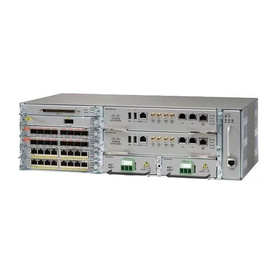
Installing the Cisco ASR 903 Router
This chapter describes how to install the Cisco ASR 903 Router.
•
•
•
•
•
•
•
•
Prerequisites
Before installing the Cisco ASR 903 Router, it is important to prepare for the installation by:
• Preparing the site (site planning) and reviewing the installation plans or method of procedures (MOP)
• Unpacking and inspecting the Cisco ASR 903 Router
• Gathering the tools and test equipment required to properly install the Cisco ASR 903 Router
For more instructions on how to prepare for the installation of the Cisco ASR 903 Router, see
Installation.
Installing the Router in a Rack
The following sections describe how to install the Cisco ASR 903 Router in a rack:
Prerequisites, page 1
Installing the Router in a Rack, page 1
Installing the Fan Tray, page 20
RSP Installation, page 23
Interface Module Installation, page 26
Installing the Power Supply, page 31
Cisco ASR 903 and ASR 903U Aggregation Services Router Hardware Installation Guide
Preparing for
1
Advertisement
Table of Contents

Related Manuals for Cisco ASR 903


Summary of Contents for Cisco ASR 903
-
Page 1: Table Of Contents
• Unpacking and inspecting the Cisco ASR 903 Router • Gathering the tools and test equipment required to properly install the Cisco ASR 903 Router For more instructions on how to prepare for the installation of the Cisco ASR 903 Router, see Preparing for Installation. -
Page 2: Installing The Chassis Brackets
Figure 1: Attaching Mounting Brackets for a 19-inch EIA Rack The figure below shows how to attach the brackets on the Cisco ASR 903 Router for a 300 mm ETSI cabinet. Figure 2: Attaching Mounting Brackets for a 300 mm ETSI Cabinet Step 2 Position one of the brackets against the chassis side, and align the screw holes. -
Page 3: Installing The Router Chassis In The Rack
• If the rear of the chassis is at the front of the rack, insert the front of the chassis between the mounting posts. Step 2 Align the mounting holes in the bracket (and optional cable guide) with the mounting holes in the equipment rack. Cisco ASR 903 and ASR 903U Aggregation Services Router Hardware Installation Guide... - Page 4 Figure 3: Installing the Chassis in a 19-inch EIA Rack Figure 4: Installing the Chassis to support the Japanese JIS Rack Standard Figure 5: Installing the Chassis in a 300 mm ETSI Cabinet Cisco ASR 903 and ASR 903U Aggregation Services Router Hardware Installation Guide...
- Page 5 Installing the Cisco ASR 903 Router Installing the Router Chassis in the Rack Figure 6: Vertical Mounting Installation Cisco ASR 903 and ASR 903U Aggregation Services Router Hardware Installation Guide...
- Page 6 Install the 8 or 12 (4 or 6 per side) 12-24 x 3/4-inch or 10-32 x 3/4-inch screws through the holes in the bracket and into the threaded holes in the equipment rack posts. Step 4 Use a tape measure and level to verify that the chassis is installed straight and level. Cisco ASR 903 and ASR 903U Aggregation Services Router Hardware Installation Guide...
- Page 7 Installing the Router Chassis in the Rack Installing Plenum A903-F2B-AIR-U Assembly and Chassis in the Rack Following steps help you to install the plenum assembly irrespective of the chassis and rack size. Cisco ASR 903 and ASR 903U Aggregation Services Router Hardware Installation Guide...
- Page 8 Position the air baffle and the side plate to the plenum. Secure the air baffle and the side plate using a maximum torque of 11.5 in.-lb (1.3 N-m). See figure below. Figure 8: Securing the Air Baffle Tray Cisco ASR 903 and ASR 903U Aggregation Services Router Hardware Installation Guide...
- Page 9 Installing the Cisco ASR 903 Router Installing the Router Chassis in the Rack Air baffle Plenum base Side plate Secure screw to Plenum base Cisco ASR 903 and ASR 903U Aggregation Services Router Hardware Installation Guide...
- Page 10 Secure the air baffle using a maximum torque of 11.5 in.-lb (1.3 N-m). See figure below. Figure 9: Securing the Side Plate Securing side plate to — — plenum base Cisco ASR 903 and ASR 903U Aggregation Services Router Hardware Installation Guide...
- Page 11 11.5 in.-lb (1.3 N-m). See figure below. Figure 10: Air Filter The filter is applicable only when fans A903-FAN and A903-FAN-H are used and the filter is not applicable Note for A903-FAN-E. Cisco ASR 903 and ASR 903U Aggregation Services Router Hardware Installation Guide...
- Page 12 Step 6 Position the plenum assembly to the rack and secure the cable brackets to the rack using a torque of 11.5 in.-lb (1.3 N-m). See figure below. Cisco ASR 903 and ASR 903U Aggregation Services Router Hardware Installation Guide...
- Page 13 Installing the Router Chassis in the Rack Note For a 19-inch rack installation, the rack has to have a flat post. Figure 12: Plenum Assembly to 21-inch Rack Cisco ASR 903 and ASR 903U Aggregation Services Router Hardware Installation Guide...
- Page 14 Installing the Cisco ASR 903 Router Installing the Router Chassis in the Rack Figure 13: Plenum Assembly to 23-inch Rack Secure screws to rack — — Cisco ASR 903 and ASR 903U Aggregation Services Router Hardware Installation Guide...
-
Page 15: Attaching The Cable Management Brackets
Attaching the Cable Management Brackets The router supports the following brackets: • A903-CABLE-GUIDE • A903-CAB-BRACKET—This bracket helps in routing the cables from the interface modules; therefore enabling a proper cable bending radius. Cisco ASR 903 and ASR 903U Aggregation Services Router Hardware Installation Guide... - Page 16 Figure 15: Cable Management Bracket Installation Figure 16: Cable Management Bracket (A903-CAB-BRACKET) Step 2 Secure the cable management brackets with four M4 screws. The recommended maximum torque is 10 in.-lb (1.12 N-m). Cisco ASR 903 and ASR 903U Aggregation Services Router Hardware Installation Guide...
-
Page 17: Installing The Chassis Ground Connection
Installing the Chassis Ground Connection Installing the Chassis Ground Connection Before you connect the power or turn on the power to the Cisco ASR 903 Router, you must provide an adequate chassis ground (earth) connection to your router. This section describes how to ground the Cisco ASR 903 Router chassis. The router provides two locations for attaching a 2-hole grounding lug according to the rack-mounting brackets you use to install the router. - Page 18 • 6 AWG or larger copper wire for the ground wire • Wire-stripping tools appropriate to the wire you are using Before making connections to the Cisco ASR 903 Router, ensure that you disconnect the power at the Caution circuit breaker. Otherwise, severe injury to you or damage to the router may occur.
- Page 19 Installing the Cisco ASR 903 Router Installing the Chassis Ground Connection Perform the following procedure to ground the Cisco ASR 903 Router using a 2-hole lug and the corresponding mounting point. Most carriers require a minimum 6 AWG ground connection. Verify your carrier’s requirements for the ground connection.
-
Page 20: Installing The Fan Tray
Installing the Cisco ASR 903 Router Installing the Fan Tray Installing the Fan Tray The fan tray is a modular unit that provides cooling to the Cisco ASR 903 Router. Follow these steps to install the fan tray in the chassis: Step 1 Orient the fan tray so that the captive screws are on the left side of the fan tray’s front panel. -
Page 21: Installing The Dust Filter
Removing and Replacing the Fan Tray The fan tray supports online insertion and removal (OIR). There is no need to power down the Cisco ASR 903 Router to remove or replace the fan tray. However, there is a finite time to replace the fan tray. This time depends upon the specific RSP and fan tray combination and also the ambient temperature. - Page 22 This is applicable when the RSP1 and RSP2 modules are installed in the chassis. Follow these steps to remove and replace the fan tray on the Cisco ASR 903 Router: Step 1 Using a No. 2 Phillips screwdriver or your fingers, loosen the captive installation screw that secures the fan tray to the chassis.
-
Page 23: Rsp Installation
To install the new fan tray, follow the steps inInstalling the Fan Tray. RSP Installation Follow these steps on handling an RSP module in the Cisco ASR 903 Router: Cisco ASR 903 and ASR 903U Aggregation Services Router Hardware Installation Guide... -
Page 24: Installing An Rsp Module
Note toward the open slot, which reduces the size of the opening and makes it difficult to install the new module. Blank module filler plates (Cisco part number A900-RSPA-BLANK) should be installed in any empty chassis Note slots to keep dust out of the chassis and to maintain consistent airflow through the chassis. -
Page 25: Removing An Rsp Module
Loosen the two captive installation screws on the module you plan to remove from the chassis. Step 4 Place your thumbs on the ejector levers (see the figure Cisco ASR 903 Router RSP Installation ) and simultaneously rotate the ejector levers outward to unseat the module from the backplane connector. -
Page 26: Interface Module Installation
Hot-Swapping an RSP Module The Cisco ASR 903 Router provides a feature that allows you to remove and replace a redundant RSP module without powering down the router. This feature, called hot-swapping or OIR, allows you to remove and replace a redundant module without disrupting router operation. -
Page 27: Installing An Interface Module
Close all unused SFP ports using SFP dust caps to prevent dust from accumulating inside the cage. The dust Note caps (Cisco part number A900-DCAP-SFP-S= (24 caps per package) or Cisco part number A900-DCAP-SFP-L= (240 caps per package)) can be ordered from Cisco. -
Page 28: Removing An Interface Module
Hot-Swapping an Interface Module The Cisco ASR 903 Router provides a feature that allows you to remove and replace an interface module without powering down the router. This feature, called hot-swapping or OIR, allows you to remove and replace a redundant module without disrupting router operation. - Page 29 Use the hw-module subslot default command before performing a swap of the modules. to default the interfaces on the interface module. The hw-module subslot default command is not supported on the TDM and OC-3 interface modules. Note Cisco ASR 903 and ASR 903U Aggregation Services Router Hardware Installation Guide...
- Page 30 Interface Module Ethernet interface (8X10GE) modules 1-port 100 Gigabit No support No support Ethernet Interface Module (1X100GE) 2-port 40 Gigabit Ethernet No support No support QSFP Interface Module (2X40GE) Cisco ASR 903 and ASR 903U Aggregation Services Router Hardware Installation Guide...
-
Page 31: Installing The Power Supply
Do not use interface module and power supply ejector handles to lift the chassis; using the handles to lift Caution the chassis can deform or damage the handles. Cisco ASR 903 and ASR 903U Aggregation Services Router Hardware Installation Guide... -
Page 32: Preventing Power Loss
DC Power Specifications to estimate the power requirements and heat dissipation of a Cisco ASR 903 Router based on a given configuration of the router. Determining power requirements is useful for planning the power distribution system needed to support the router. -
Page 33: Installing The Dc Power Supply
This equipment is suitable for installations utilizing the Common Bonding Network (CBN). Note The grounding architecture of this product is DC-Isolated (DC-I) for DC-powered products. DC-powered Note products have a nominal operating DC voltage of 48 VDC. Cisco ASR 903 and ASR 903U Aggregation Services Router Hardware Installation Guide... -
Page 34: Installing The Dc Power Supply Module
8 AWG cable. The lug is assembled on the unit with two nuts. Warning Before performing any of the following procedures, ensure that power is removed from the DC circuit. Cisco ASR 903 and ASR 903U Aggregation Services Router Hardware Installation Guide... - Page 35 Use a wire-stripping tool to strip the ends of each of the two wires coming from the DC-input power source as recommended by the lug manufacturer. Stripping more than the recommended amount of wire can leave behind exposed wire from the terminal block Note after installation. Cisco ASR 903 and ASR 903U Aggregation Services Router Hardware Installation Guide...
- Page 36 Use a tie wrap to secure the wires to the rack, so that the wires are not pulled from the terminal block by casual contact. Make sure the tie wrap allows for some slack in the wire. Cisco ASR 903 and ASR 903U Aggregation Services Router Hardware Installation Guide...
-
Page 37: Activating The Dc Power Supply
If you are installing a redundant DC power supply, repeat these steps for the second power source. Removing and Replacing the DC Power Supply This section provides information about removing and replacing the DC power supply in the Cisco ASR 903 Router. -
Page 38: Installing The Ac Power Supply
Replace the DC power supply within 5 minutes. If the power supply bay is to remain empty, install a blank filler Note plate (Cisco part number A900-PWR-BLANK) over the opening, and secure it with the captive installation screws. Installing the AC power Supply... - Page 39 Slide the power supply into the power supply bay. Make sure that the power supply is fully seated in the bay. Figure 28: Installing the A900-PWR550-A AC Power Supply Cisco ASR 903 and ASR 903U Aggregation Services Router Hardware Installation Guide...
- Page 40 We recommend the following power cables for Cisco ASR 903 routers: Table 3: Power Cable PIDs for A900-PWR550-A (550 W) Description CAB-AC AC POWER CORD, UNITED STATES, 125V, 10A, 2.5m, C13,NEMA, 5-15P Cisco ASR 903 and ASR 903U Aggregation Services Router Hardware Installation Guide...
- Page 41 Table 4: Power Cable PIDs for A900-PWR1200-A (1200 W) Description PWR-CAB-AC-USA520 US AC Power Cord for Cisco ASR 900, NEMA 5-20 PWR-CAB-AC-USA Power Cord for AC V2 Power Module (USA), NEMA L6-20P Cisco ASR 903 and ASR 903U Aggregation Services Router Hardware Installation Guide...
-
Page 42: Activating The Ac Power Supply
If you are installing a redundant AC power supply, ensure that each power supply is connected to a separate Note power source in order to prevent power loss in the event of a power failure. Cisco ASR 903 and ASR 903U Aggregation Services Router Hardware Installation Guide... -
Page 43: Removing And Replacing The Ac Power Supply
Step 5 If the power supply bay is to remain empty, install a blank filler plate (Cisco part number A900-PWR-BLANK) over the opening, and secure it with the captive installation screws. -
Page 44: Connecting The Cisco Asr 903 Router To The Network
Connecting the Cisco ASR 903 Router to the Network When installing the cabling to the RSPs, we recommend that you leave a service loop of extra cabling Note sufficient to allow for fan tray removal. Cisco ASR 903 and ASR 903U Aggregation Services Router Hardware Installation Guide... -
Page 45: Connecting Console Cables
USB port is used it takes priority over the RJ45 EIA port. Note The USB Type A-to-Type A cable is not included with the Cisco ASR 903 Router; it is ordered separately. Step 2 Connect the end of the cable with the DB-9 connector (or USB Type-A) to the terminal or PC. If your terminal or PC has a console port that does not accommodate a DB-9 connector, you must provide an appropriate adapter for that port. - Page 46 Installing the Cisco ASR 903 Router Connecting Console Cables • no flow control Figure 31: Connecting the USB Console Cable to the Cisco ASR 903 Router USB Type-A console port USB Type-A to USB Type-A Console cable USB Type-A —...
-
Page 47: Connecting To The Console Port Using Mac Os X
0 Jan 14 18:02 ttyACM0 root@usb-suse /dev# Step 4 Connect to the USB port with the following command followed by the router USB port speed Example: root@usb-suse /dev# screen /dev/ttyACM0 9600 Cisco ASR 903 and ASR 903U Aggregation Services Router Hardware Installation Guide... -
Page 48: Installing The Cisco Microsoft Windows Usb Device Driver
Found New Hardware Wizard appears. Following the instructions to complete the installation of the driver. Step 7 The USB console is ready for use. Cisco ASR 903 and ASR 903U Aggregation Services Router Hardware Installation Guide... - Page 49 “Installing device driver software” appears. Following the instructions to complete the installation of the driver. Step 7 The USB console is ready for use. Cisco ASR 903 and ASR 903U Aggregation Services Router Hardware Installation Guide...
-
Page 50: Uninstalling The Cisco Microsoft Windows Usb Driver
Installing the Cisco ASR 903 Router Connecting Console Cables Uninstalling the Cisco Microsoft Windows USB Driver Uninstalling the Cisco Microsoft Windows XP and 2000 USB Driver Using the Add Remove Programs Utility Note Disconnect the chassis console terminal before uninstalling the driver. -
Page 51: Connecting To The Auxiliary Port
DB-9-to-DB-25 connector adapter. Note The console cable and DB-9-to-DB-25 connector are not included with the Cisco ASR 903 Router; they are ordered separately. To connect a modem to the router, follow these steps: Step 1 Connect the RJ45 end of the adapter cable to the black AUX port on the router, as shown in the figure below . -
Page 52: Connecting A Management Ethernet Cable
Installing and Removing SFP and XFP Modules The Cisco ASR 903 Router supports a variety of SFP and XFP modules, including optical and Ethernet modules. For information on how to install and remove SFP and XFP modules, see the documentation for the SFP or XFP module at: http://www.cisco.com/en/US/partner/products/hw/modules/ps5455/prod_installation_guides_list.html... -
Page 53: Connecting A Usb Flash Device
Connecting a USB Flash Device To connect a USB flash device to the Cisco ASR 903 Router, insert the memory stick in the USB port labeled MEM. The Flash memory module can be inserted in only one way, and can be inserted or removed regardless of whether the router is powered up or not. -
Page 54: Connecting Timing Cables
RJ45 Cat5 1-to-2 splitter (3 female port RJ45 connector). Note When installing the cabling to the RSPs, we recommend that you leave a service loop of extra cabling sufficient to allow for fan tray removal. Cisco ASR 903 and ASR 903U Aggregation Services Router Hardware Installation Guide... - Page 55 Step 3 Connect the other end of the split-side Y-cable Ethernet to the ToD port on the backup RSP of the Cisco ASR 903 Router. For instructions on how to configure clocking, see the Cisco ASR 903 Router Software Configuration Guide.
-
Page 56: Connecting Ethernet Cables
Screw on the GNSS Module Inserting the GNSS Module Connecting Ethernet Cables The Cisco ASR 903 Router interface modules support RJ45 or SFP Ethernet ports. For instructions on how to connect cables to Ethernet SFP ports, see Connecting Cables to SFP Modules. -
Page 57: Connecting Cables To Sfp Modules
For information on connecting cables to Cisco optical and Ethernet SFP interfaces, see http://www.cisco.com/en/US/partner/products/hw/modules/ps5455/prod_installation_guides_list.html. Connecting T1/E1 cables The physical layer interface for the Cisco ASR 903 Router T1/E1 port is a customer-installed high-density connector. The high-density connector has thumbscrews which should be screwed into the interface when the cable is installed. - Page 58 Figure 36: Cable Installation between 16 x T1/E1 Interface and Patch Panel Patch panel interfaces For information about the pinout of the cable connecting the T1/E1 interface to the rear of the patch panel, see the T1/E1 Port Pinout Cisco ASR 903 and ASR 903U Aggregation Services Router Hardware Installation Guide...
- Page 59 The other end of the cable has two 50-pin Telco connectors that attach to the rear of a 24-port RJ45 patch panel. Both connectors are identical: one is for Transmit (TX) and the other is for Receive (RX). Cisco ASR 903 and ASR 903U Aggregation Services Router Hardware Installation Guide...
- Page 60 • If both T1/E1 interfaces are connected to their patch panels in the same manner (TX to Transmit and RX to Receive, or TX to Receive and RX to Transmit), use a T1 cross-over cable to connect the patch panels. Cisco ASR 903 and ASR 903U Aggregation Services Router Hardware Installation Guide...
-
Page 61: Recommended Patch Panel
800-622-7711 (toll-free in the U.S.A.) ◦ 540-265-0690 (outside the U.S.A.) Connecting Serial Cables The tables below detail the supported cables with the Cisco ASR 903 Router. Note The Cisco ASR 903 Router currently only supports the EIA/TIA-232 connector. Cisco ASR 903 and ASR 903U Aggregation Services Router Hardware Installation Guide... - Page 62 10 ft. Female RJ-45 4-port EIA-232 CAB-QUAD-ASYNC-M 10 ft. Male RJ-45 4-port EIA-232 CAB-9AS-M 10 ft. Male DB-9 For more information on cable specifications and pinouts, see Troubleshooting. Cisco ASR 903 and ASR 903U Aggregation Services Router Hardware Installation Guide...
-
Page 63: Connecting The Fan Tray Alarm Port
OSP wiring. Only Pins 1, 2, 4, 5, and 8 are available for customer use. The remaining pins are for Cisco manufacturing test, and should not be connected. Use a shielded cable for connection to this port for EMC protection. Table 5-6 summarizes the pinouts on the alarm port in Troubleshooting. - Page 64 Installing the Cisco ASR 903 Router Connector and Cable Specifications Cisco ASR 903 and ASR 903U Aggregation Services Router Hardware Installation Guide...
Need help?
Do you have a question about the ASR 903 and is the answer not in the manual?
Questions and answers