Cisco ASR 903 Hardware Installation Manual
Hide thumbs
Also See for ASR 903:
- Release notes (280 pages) ,
- Installation manual (200 pages) ,
- Manual (147 pages)
Table of Contents
Advertisement
Quick Links
Advertisement
Table of Contents

Related Manuals for Cisco ASR 903


Summary of Contents for Cisco ASR 903
- Page 1 Cisco ASR 903 Aggregation Services Router Hardware Installation Guide First Published: 2015-10-01 Americas Headquarters Cisco Systems, Inc. 170 West Tasman Drive San Jose, CA 95134-1706 http://www.cisco.com Tel: 408 526-4000 800 553-NETS (6387) Fax: 408 527-0883...
- Page 2 Cisco and the Cisco logo are trademarks or registered trademarks of Cisco and/or its affiliates in the U.S. and other countries. To view a list of Cisco trademarks, go to this URL: www.cisco.com/go/trademarks . Third-party trademarks mentioned are the property of their respective owners. The use of the word partner does not imply a partnership relationship between Cisco and any other company.
-
Page 3: Table Of Contents
Fan Tray (A903-FAN-E) Dust Filter (A903-FAN-F) Air Plenum RSP Modules Supported RSPs A900-RSP1 Supported Interface Modules A900-RSP2 Supported Interface Modules A900-RSP3C-400-S Supported Interface Modules A900-RSP3C-200-S Supported Interface Modules Supported RSP Features Cisco ASR 903 Aggregation Services Router Hardware Installation Guide... - Page 4 8-Port 1 10/100/1000 Gigabit Ethernet + 1-Port 10 Gigabit Ethernet SFP+ Combination Interface Module 2-Port 10 Gigabit Ethernet SFP+ Interface Module Blank Deflector (A900-IMA-BLNK-DEF) Maximum Operating Ambient Temperature Support for RSP3 Modules Example: Configuration with A900-RSP3-200-S with Blank Deflector (A900-IMA-BLNK-DEF) Temperature Sensor Cisco ASR 903 Aggregation Services Router Hardware Installation Guide...
- Page 5 Electrical Circuit Requirements Site Cabling Guidelines Asynchronous Terminal Connections Interference Considerations Electromagnetic Interference Radio Frequency Interference Lightning and AC Power Fault Interference Rack-Mounting Guidelines Precautions for Rack-Mounting Rack Selection Guidelines Equipment Rack Guidelines Cisco ASR 903 Aggregation Services Router Hardware Installation Guide...
- Page 6 Hot-Swapping an RSP Module Interface Module Installation Installing an Interface Module Removing an Interface Module Hot-Swapping an Interface Module Swapping of Interface Modules Installing the Power Supply Preventing Power Loss Power Connection Guidelines Cisco ASR 903 Aggregation Services Router Hardware Installation Guide...
- Page 7 Installing the Cisco Microsoft Windows Vista USB Driver Uninstalling the Cisco Microsoft Windows USB Driver Uninstalling the Cisco Microsoft Windows XP and 2000 USB Driver Using the Add Remove Programs Utility Uninstalling the Cisco Microsoft Windows XP and 2000 USB Driver Using the Setup.exe Program...
- Page 8 Checking the Running Configuration Settings Saving the Running Configuration to NVRAM Safely Powering Off the Cisco ASR 903 Router Troubleshooting C H A P T E R 5 BITS Port Pinout GPS Port Pinout Cisco ASR 903 Aggregation Services Router Hardware Installation Guide viii...
- Page 9 E and M Interface Module LEDs 4-Port C37.94 Interface Module LEDs Power Supply LEDs Fan Tray LEDs Alarm Conditions Site Log and Manufactures A P P E N D I X A Manufactures Cisco ASR 903 Aggregation Services Router Hardware Installation Guide...
- Page 10 Contents Cisco ASR 903 Aggregation Services Router Hardware Installation Guide...
-
Page 11: Document Revision History
Preface This preface describes the revision history, audience, organization, and conventions of the Cisco ASR 903 Router Hardware Installation Guide. It also lists sources for obtaining additional information and technical assistance from Cisco Systems. • Document Revision History, page xi •... -
Page 12: Document Organization
Initial release Document Audience This guide is intended for users who are responsible for installing the Cisco router. It is intended for users who may not be familiar with the initial configuration and troubleshooting tasks, the relationship among tasks, or the Cisco IOS software commands necessary to perform particular tasks. -
Page 13: Document Conventions
Preface Document Conventions Title Description “Installing the Cisco ASR 903 Router, on This chapter describes the Cisco ASR 903 Router and Chapter 3, how to install it. page 79” Chapter 4, “Cisco ASR 903 Initial Configuration, on This chapter describes how to start the Cisco ASR 903 Router and create an initial system configuration. - Page 14 The following conventions are used to attract the attention of the reader: Caution Means reader be careful . In this situation, you might do something that could result in equipment damage or loss of data. Cisco ASR 903 Aggregation Services Router Hardware Installation Guide...
-
Page 15: Obtaining Documentation And Submitting A Service Request
Obtaining Documentation and Submitting a Service Request For information on obtaining documentation, submitting a service request, and gathering additional information, see the monthly What’s New in Cisco Product Documentation , which also lists all new and revised Cisco technical documentation, at: http://www.cisco.com/en/US/docs/general/whatsnew/whatsnew.html... - Page 16 Preface Obtaining Documentation and Submitting a Service Request Cisco ASR 903 Aggregation Services Router Hardware Installation Guide...
-
Page 17: Cisco Asr 903 Router Features
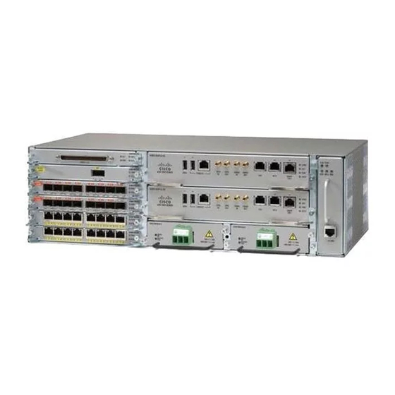
3-rack-unit (RU) router provides high service scale, full redundancy, and flexible hardware configuration. The Cisco ASR 903 Router expands the Cisco service provider product portfolio by providing a rich and scalable feature set of Layer 2 VPN (L2VPN) and Layer 3 VPN (L3VPN) services in a compact package. -
Page 18: Power Supply Features
Redundant power units (two DC power units are shown) Power Supply Features The Cisco ASR 903 Router support AC and DC power supplies. For more information about installing the Cisco ASR 903 Router power supplies, see the Installing the Power Supply. -
Page 19: Redundancy
Redundancy is supported either with identical power supplies or a combination of AC and DC power supply. The Cisco ASR 903 Router supports current sharing between the power supplies. - Page 20 As most of the system configurations using A900-RSP3C-400-S RSP modules require power exceeding 550 W, we recommend using the A900-PWR1200-D power supply with A900-RSP3C-400-S RSP modules. Figure 2: DC PSU Module (A900-PWR550-D) with Euro-style Connector Euro-style connector — Cisco ASR 903 Aggregation Services Router Hardware Installation Guide...
-
Page 21: Cisco Asr 903 Aggregation Services Router Hardware Installation Guide
T-shaped connector — Table 1: DC Power Supply Specifications (550 W) Part numbers A900-PWR550-D, A900-PWR550-D-E Input power specification +24V/-48V or -60V VDC Minimum input voltage 19.2 VDC Maximum input voltage 72 VDC Cisco ASR 903 Aggregation Services Router Hardware Installation Guide... -
Page 22: Cisco Asr 903 Aggregation Services Router Hardware Installation Guide
10 AWG minimum for –48/–60 VDC. 8 AWG minimum for 24 VDC. Connector accepts 8 AWG maximum. Maximum power output 550 W Figure 4: DC PSU Module (A900-PWR1200-D) Label Component T-shaped connector Cisco ASR 903 Aggregation Services Router Hardware Installation Guide... -
Page 23: Ac Power Specifications
• A900-PWR550-A—Provides 550 W output power for system 12 V power. Uses an IEC 320 C14 type 15 Amp power receptacle connector, The A900-PWR550-A power supply can be used with the A900-RSP3C-400-S RSP modules only if the power consumption is within 550 W. However, A900-PWR1200-A is recommended. Cisco ASR 903 Aggregation Services Router Hardware Installation Guide... -
Page 24: Cisco Asr 903 Aggregation Services Router Hardware Installation Guide
550 W, we recommend using the A900-PWR1200-A power supply with A900-RSP3C-400-S RSP modules. See the figure below. Figure 5: AC Power Supply (A900-PWR1200-A) Table 4: AC Power Supply Specifications (A900-PWR1200-A) Part number A900-PWR1200-A Cisco ASR 903 Aggregation Services Router Hardware Installation Guide... -
Page 25: Fan Tray
For more information about air flow guidelines, see Air Flow Guidelines . For instructions on how to install the fan tray, see Installing the Fan Tray . For a summary of the LEDs on the fan tray, see LED Summary. Cisco ASR 903 Aggregation Services Router Hardware Installation Guide... -
Page 26: Fan Tray (A903-Fan)
Fan Tray Fan Tray (A903-FAN) The Cisco ASR 903 Router uses a modular fan tray that is separate from the power supply. The fan tray contains twelve fans and provides sufficient capacity to maintain operation indefinitely in the event of an individual fan failure. -
Page 27: Dust Filter (A903-Fan-F)
Cisco ASR 903 Router Overview Fan Tray prevents dust from entering the unit and avoids possible damage to the components. The fan tray is IEC60950-1 compliant. Figure 7: Cisco ASR 903 Fan Tray with Dust Filter and Dummy Cover (A903-FAN-E) LEDs Dummy cover Alarm... -
Page 28: Air Plenum
RSP Modules The Cisco ASR 903 Router is designed to use up to two RSP modules to handle the data plane, network timing, and control plane functionalities for the router. The RSP configuration allows you to use Cisco IOS software to control chassis management, redundancy, external management, and system status indications on the router. -
Page 29: Cisco Asr 903 Aggregation Services Router Hardware Installation Guide
• A900-RSP3C-200-S—Provides 8 GB of SDRAM and non-volatile memory, 64MB flash memory, 20 Mb of TCAM memory, 200Gbps throughput. The supported RSPs have different memory capacities, but they have the same interfaces and functionality. Note Cisco ASR 903 Aggregation Services Router Hardware Installation Guide... -
Page 30: Cisco Asr 903 Aggregation Services Router Hardware Installation Guide
The SD memory card is not field replaceable. Do not try to remove or replace it. Caution Figure 8: A900-RSP1 Module Figure 9: A900-RSP2A-128 Module SD memory card SD memory card slot Installing a mix of RSP modules in the chassis is not supported. Note Cisco ASR 903 Aggregation Services Router Hardware Installation Guide... -
Page 31: Cisco Asr 903 Aggregation Services Router Hardware Installation Guide
RSP Modules The RSPs do not provide external network interfaces for user traffic. All network interfaces are provided via separate IMs. Figure 10: A900-RSP3C-400-S RSP Module Figure 11: A900-RSP3C-200-S RSP Module Cisco ASR 903 Aggregation Services Router Hardware Installation Guide... -
Page 32: A900-Rsp1 Supported Interface Modules
The combination IMs (A900-IMA8S1Z, A900-IMA8T1Z), and the A900-IMA2Z are not supported on Note the A900-RSP1A-55 and A900-RSP1B-55 modules on the Cisco ASR 903 Router. • The combination IMs (A900-IMA8S1Z, A900-IMA8T1Z) are not supported on the A900-RSP2-64 RSP module on the Cisco ASR 903 Router. -
Page 33: Cisco Asr 903 Aggregation Services Router Hardware Installation Guide
(8x1GE) + 1-port 10 Gigabit Ethernet Interface Module (1x10GE) 2-port 10 Gigabit Ethernet Interface A900-IMA2Z Module (2x10GE) 6-port E & M Interface Module A900-IMA6EM 14-port Serial Interface Module A900-IMASER14A/S 4-port C37.94 Interface Module A900-IMA4C3794 Cisco ASR 903 Aggregation Services Router Hardware Installation Guide... -
Page 34: Cisco Asr 903 Aggregation Services Router Hardware Installation Guide
16-port T1/E1 Interface Module A900-IMA16D 32-port T1/E1 Interface Module A900-IMA32D 8-port T1/E1 Interface Module A900-IMA8D 6-port E & M Interface Module A900-IMA6EM 14-port Serial Interface Module A900-IMASER14A/S 4-port C37.94 Interface Module A900-IMA4C3794 Cisco ASR 903 Aggregation Services Router Hardware Installation Guide... -
Page 35: A900-Rsp3C-400-S Supported Interface Modules
Ethernet Interface Module (1x10GE) 2-port 10 Gigabit Ethernet A900-IMA2Z Interface Module (2x10GE) 8-port 10 Gigabit Ethernet A900-IMA8Z Interface Module (8x10GE) 1-port 100 Gigabit A900-IMA1C 4 and 5 Ethernet Interface Module (1x100GE) Cisco ASR 903 Aggregation Services Router Hardware Installation Guide... -
Page 36: Cisco Asr 903 Aggregation Services Router Hardware Installation Guide
A900-IMA48D-C Interface Module 48 X T3/E3 CEM A900-IMA48T-C Interface Module 1 There are restrictions using the interface modules in different slots with RSP3 module. Contact Cisco Sales/Support for the valid combinations.. Cisco ASR 903 Aggregation Services Router Hardware Installation Guide... -
Page 37: A900-Rsp3C-200-S Supported Interface Modules
(8x10GE) 2-port 40 Gigabit Ethernet A900-IMA2F QSFP Interface Module (2x40GE) 2 There are restrictions using the interface modules in different slots with RSP3 module. Contact Cisco Sales/Support for the valid combinations.. Cisco ASR 903 Aggregation Services Router Hardware Installation Guide... -
Page 38: Rsp Redundancy
RSP Redundancy The Cisco ASR 903 Router chassis includes two RSP slots to allow for redundant RSPs. When the router uses redundant RSPs, one RSP operates in the active mode and the other operates in the hot standby mode. Removal or failure of the active RSP results in an automatic switchover to the standby RSP. -
Page 39: Rsp Interfaces
1 PPS output timing port 10 MHz input timing port 10 MHz output timing port Time of Day (ToD) timing port BITS timing port Ethernet management port Figure 13: Cisco A900-RSP2A Interface Summary Cisco ASR 903 Aggregation Services Router Hardware Installation Guide... -
Page 40: Cisco Asr 903 Aggregation Services Router Hardware Installation Guide
Time of Day (ToD) timing port BITS timing port Ethernet management port The Cisco A900-RSP2A module has the following front panel interfaces. For information on cable pinout, see Troubleshooting. • 1 USB Type-A Connector for USB-flash (Label = “MEM”) • 1 USB Type-A Connector for alternate console port (Label = “CONSOLE”) •... -
Page 41: Cisco Asr 903 Aggregation Services Router Hardware Installation Guide
Ethernet management port Figure 15: Cisco A900-RSP3C-200-S Interfaces Label Interface GNSS module slot (optional) USB memory port USB console port Console port 1 PPS input timing port 1 PPS output timing port Cisco ASR 903 Aggregation Services Router Hardware Installation Guide... -
Page 42: Gnss Module (A900-Cm-Gnss)
22dB to 30dB with a minimum of 20dB and a maximum of 35dB. • GNSS module provides 5V to the active antenna through the same RF input. • Surge requirement: Cisco ASR 903 Aggregation Services Router Hardware Installation Guide... -
Page 43: Interface Modules
Pinout. Interface Modules The Cisco ASR 903 Router interface modules are a field-replaceable units. In addition to the ports provided on an RSP, the Cisco ASR 903 Router supports the following interface modules: For information about supported interface modules, see the Release Notes for the Cisco ASR 903 Series Note Aggregation Services Router . -
Page 44: 8-Port 1 Gigabit Ethernet Sfp Interface Module
For information on supported SFP modules, see Cisco ASR 900 Series Aggregation Services Routers Data Sheet. For more information about installing an SFP Gigabit Ethernet module, see the Interface Module Installation. Cisco ASR 903 Aggregation Services Router Hardware Installation Guide... -
Page 45: 8-Port 1Gigabit Ethernet Rj45 Interface Module
The 10-Port Gigabit Ethernet XFP interface module provides a single port supporting a 10 Gigabit Ethernet XFP module. The figure below shows the interface module. Figure 18: 1-port 10 Gigabit Ethernet XFP Interface Module Cisco ASR 903 Aggregation Services Router Hardware Installation Guide... -
Page 46: 8-Port 10 Gigabit Ethernet Interface Module (8X10Ge)
To remove the configuration, use no hw-module subslot command. For information on supported SFP modules, see Cisco ASR 900 Series Aggregation Services Routers Data Sheet. For more information about installing a 8x10GE module, see the Interface Module Installation. Cisco ASR 903 Aggregation Services Router Hardware Installation Guide... -
Page 47: 1-Port 100 Gigabit Ethernet Interface Module (1X100Ge)
The 1-port 100 Gigabit Ethernet interface module supports one CPAK optics port. For information on supported CPAK modules, see Cisco ASR 900 Series Aggregation Services Routers Data Sheet. For more information about installing a 1x100GE module, see the Interface Module Installation. Cisco ASR 903 Aggregation Services Router Hardware Installation Guide... -
Page 48: 2-Port 40 Gigabit Ethernet Qsfp Interface Module (2X40Ge)
Figure 21: 2-port 40 Gigabit Ethernet Interface Module For information on supported SFP modules, see Cisco ASR 900 Series Aggregation Services Routers Data Sheet. For more information about installing a 2x40GE module, see the Interface Module Installation. Cisco ASR 903 Aggregation Services Router Hardware Installation Guide... -
Page 49: 16-Port T1/E1 Interface Module
The 32-port T1/E1 interface module provides connectivity for up to 32 T1/E1 ports through two 68-pin Tyco connectors. It is supported on the A900-RSP2A-64 module in slots 3, 4 and 5, and on the A900-RSP2A-128 on all slots. Cisco ASR 903 Aggregation Services Router Hardware Installation Guide... -
Page 50: Cisco Asr 903 Aggregation Services Router Hardware Installation Guide
Figure 23: 32-portT1/E1 Interface Module For information on supported SFP modules, see Cisco ASR 900 Series Aggregation Services Routers Data Sheet. For more information about installing a 32-portT1/E1 interface module, see the Interface Module Installation. Cisco ASR 903 Aggregation Services Router Hardware Installation Guide... -
Page 51: 8-Port T1/E1 Interface Module
For information on supported SFP modules, see Cisco ASR 900 Series Aggregation Services Routers Data Sheet. For more information about installing a 8-port T1/E1 interface module, see the Interface Module Installation. Cisco ASR 903 Aggregation Services Router Hardware Installation Guide... -
Page 52: 48-Port T1/E1 Cem Interface Module
Figure 26: 48-port T1/E1 Faceplate For information on supported SFP modules, see Cisco ASR 900 Series Aggregation Services Routers Data Sheet. For more information about installing an optical interface module, see Interface Module Installation. Cisco ASR 903 Aggregation Services Router Hardware Installation Guide... -
Page 53: 48-Port T3/E3 Cem Interface Module
4-port OC3/STM-1 (OC-3) or 1-port OC12/STM-4 (OC-12) Interface Module The 4-port OC3/STM-1 (OC-3) or 1-port OC12/STM-4 (OC-12) interface module can operate as up to four STM-1 interfaces. The figure below shows the interface module. Cisco ASR 903 Aggregation Services Router Hardware Installation Guide... -
Page 54: Cisco Asr 903 Aggregation Services Router Hardware Installation Guide
Figure 29: 4-port OC-3 Interface Module For information on supported SFP modules, see Cisco ASR 900 Series Aggregation Services Routers Data Sheet. For more information about installing an optical interface module, see Interface Module Installation. Cisco ASR 903 Aggregation Services Router Hardware Installation Guide... -
Page 55: 1-Port Oc-192 Or 8-Port Low Rate Cem Interface Module (10G Ho / 10G Lo)
◦ Maximum of 4 x OC-48 interfaces are supported per interface module ◦ For each OC-48 port enabled, neighboring SFP ports cannot be configured ◦ OC-3 and OC-12 port configuration is supported on all ports simultaneously Cisco ASR 903 Aggregation Services Router Hardware Installation Guide... -
Page 56: Port Combinations Usage Guidelines
Installation. 14-Port Serial Interface Module The Cisco (A900-IMASER14A/S) is a 14-port serial interface module for the Cisco ASR 903 router. The Cisco ASR 903 Router module has the following interfaces: • 12-in-1 Connector (6)-Supports synchronous and asynchronous RS-232 interfaces using EIA/TIA-232... -
Page 57: Cisco Asr 903 Aggregation Services Router Hardware Installation Guide
68-pin connectors • • J8-J13-Indicate the status of the 12-in-1 connectors For more information about using the LEDs to troubleshoot the Cisco ASR 903 Router, see LED Summary Cisco ASR 903 Aggregation Services Router Hardware Installation Guide... -
Page 58: Supported Standards
Cables. 6-Port E and M Interface Module The Cisco (A900-IMA6EM) is a 6-portEar and Mouth (E&M) interface module for the Cisco ASR 903 router. The interface module provides the router with connectivity to tele-protection equipments. The front panel of the module consists of: •... -
Page 59: 4-Port C37.94 Interface Module
Pinouts. 4-Port C37.94 Interface Module The Cisco (A900-IMA4C3794) is a 4-port interface module that provides IEEE C37.94-2002 compliant Nx64 kbps optical interface ports to the router. The interfaces support 50/62.5 multimode fiber at 850nm. The physical interfaces use 2.5mm ST connectors. -
Page 60: Port 1 Sfp Gigabit Ethernet With 1-Port 10 Gigabit Ethernet Combination Interface Module
For information on supported SFP modules, see Cisco ASR 900 Series Aggregation Services Routers Data Sheet. For more information about installing the 8-port1 SFP GE + 1-port 10 SFP+ Gigabit Ethernet module, see Interface Module Installation. Cisco ASR 903 Aggregation Services Router Hardware Installation Guide... -
Page 61: Module
Cisco ASR 900 Series Aggregation Services Routers Data Sheet. For more information about installing the 8-port 1 10/100/1000 GE (RJ45) + 1-port 10 SFP Gigabit Ethernet module, see Interface Module Installation. Cisco ASR 903 Aggregation Services Router Hardware Installation Guide... -
Page 62: 2-Port 10 Gigabit Ethernet Sfp+ Interface Module
Caution The A900-IMA-BLNK-DEF is module should not be used in slot 0 in the Cisco ASR 903 Router. For slot 0, always use the filler blank (A900-IMA-BLANK) when a blank filler needs to be used. -
Page 63: Cisco Asr 903 Aggregation Services Router Hardware Installation Guide
3 Maximum operating temperature of 65°C is supported only with EXT/RGD/IND optical modules. 4 A900-IMA8Z supports a maximum temperature of 65°C with A903-FAN or A903-FAN-E if A900-IMA-BLNK-DEF is used in the slot above the interface module. Cisco ASR 903 Aggregation Services Router Hardware Installation Guide... -
Page 64: Example: Configuration With A900-Rsp3-200-S With Blank Deflector
A900-IMA8Z Temperature Sensor The Cisco ASR 903 Router has a temperature sensor to detect overtemperature conditions inside the chassis. Temperature Sensors on the A900 RSP1 and A900 RSP2 modules The overtemperature detection trips at 75 degrees C +/- 5% with the ambient (inlet) trip point at 67 degrees C. -
Page 65: Serial Number Label Location
• Two RSP module slots • Two power supply slots • One fan tray slot Each network interface on a Cisco ASR 903 Router is identified by a slot number and a port number. Cisco ASR 903 Aggregation Services Router Hardware Installation Guide... -
Page 66: Cisco Asr 903 Aggregation Services Router Hardware Installation Guide
Cisco ASR 903 Router Overview Interface Numbering The figure below shows interface numbering in a Cisco ASR 903 Router. Figure 41: Cisco ASR 903 Router Slot Numbers RSP slot 1 RSP slot 0 Fan tray slot Power supply slot 1... -
Page 67: Regulatory Compliance
• show platform software memory iomd • set platform software trace iomd Regulatory Compliance For regulatory compliance and safety information, see the Regulatory Compliance and Safety Information for the Cisco ASR 903 Router document. Cisco ASR 903 Aggregation Services Router Hardware Installation Guide... -
Page 68: Cisco Asr 903 Aggregation Services Router Hardware Installation Guide
Cisco ASR 903 Router Overview Regulatory Compliance Cisco ASR 903 Aggregation Services Router Hardware Installation Guide... -
Page 69: Chapter 2 Preparing For Installation
C H A P T E R Preparing for Installation This chapter describes how to prepare for the installation of the Cisco ASR 903 Router at your site. • Safety Guidelines, page 53 • Site Planning, page 63 • Receiving the Cisco ASR 903 Router, page 74... -
Page 70: Cisco Asr 903 Aggregation Services Router Hardware Installation Guide
Never install telephone jacks in wet locations unless the jack is specifically designed for wet locations. Warning Statement 1036 Never touch uninsulated telephone wires or terminals unless the telephone line has been disconnected at Warning the network interface. Statement 1037 Cisco ASR 903 Aggregation Services Router Hardware Installation Guide... -
Page 71: Cisco Asr 903 Aggregation Services Router Hardware Installation Guide
Warning This is a class A product. In a domestic environment this product may cause radio interference in which case the user may be required to take adequate measures. Statement 340 Cisco ASR 903 Aggregation Services Router Hardware Installation Guide... -
Page 72: Safety Guidelines For Personal Safety And Equipment Protection
Class 1M laser radiation when open. Do not view directly with optical instruments. Statement 1053 Warning Class 1 (CDRH) and Class 1M (IEC) laser products. Statement 1055 Warning Warning Do not stare into the beam or view it directly with optical instruments. Statement 1011 Cisco ASR 903 Aggregation Services Router Hardware Installation Guide... -
Page 73: Safety With Electricity
Nevertheless, if the on-premise wiring is in close proximity to or not shielded from, the off-premise wiring or power cable during a lightning strike or power surge, the on-premise wiring can carry a dangerous discharge to the attached interface, equipment, or nearby personnel. Statement 338 Cisco ASR 903 Aggregation Services Router Hardware Installation Guide... -
Page 74: Cisco Asr 903 Aggregation Services Router Hardware Installation Guide
Statement 1017 Warning Take care when connecting units to the supply circuit so that wiring is not overloaded. Statement 1018 Cisco ASR 903 Aggregation Services Router Hardware Installation Guide... -
Page 75: Cisco Asr 903 Aggregation Services Router Hardware Installation Guide
Statement 1032 Connect the unit only to DC power source that complies with the safety extra-low voltage (SELV) Warning requirements in IEC 60950 based safety standards. Statement 1033 Cisco ASR 903 Aggregation Services Router Hardware Installation Guide... -
Page 76: Cisco Asr 903 Aggregation Services Router Hardware Installation Guide
Failure to securely tighten the power and relay connector captive screws can result in an electrical arc if Warning the connector is accidentally removed. Statement 397 This equipment is intended to be grounded. Ensure that the host is connected to earth ground during normal Warning use. Cisco ASR 903 Aggregation Services Router Hardware Installation Guide... -
Page 77: Cisco Asr 903 Aggregation Services Router Hardware Installation Guide
In addition, use the following guidelines when working with any equipment that is disconnected from a power source, but still connected to telephone wiring or network cabling: • Never install telephone wiring during a lightning storm. Cisco ASR 903 Aggregation Services Router Hardware Installation Guide... -
Page 78: Power Supply Considerations
• Avoid contact between the printed circuit boards and clothing. The wrist strap only protects components from ESD voltages on the body; ESD voltages on clothing can still cause damage. • Never attempt to remove the printed circuit board from the metal carrier. Cisco ASR 903 Aggregation Services Router Hardware Installation Guide... -
Page 79: Site Planning
• The site meets the environmental requirements. • The site’s air conditioning system can compensate for the heat dissipation of the Cisco ASR 903 Router. • The floor space that the Cisco ASR 903 Router occupies can support the weight of the system. -
Page 80: Site Selection Guidelines
Routers Data Sheet. For an outside plant installation (cell site cabinet, hut etc.), it is required that the Cisco ASR 903 Router be protected against airborne contaminants, dust, moisture, insects, pests, corrosive gases, polluted air or other reactive elements present in the outside air. To achieve this level of protection, we recommend that the unit be installed in a fully sealed enclosure or cabinet. -
Page 81: Air Flow Guidelines
Air Flow Guidelines Air Flow Guidelines Cool air is circulated through the Cisco ASR 903 Router by a fan tray located along the right side of the router. Air flow is side-to-side, right to left, as shown in the figure below . -
Page 82: Air Flow Guidelines For Enclosed Rack Installation
Air Flow Guidelines for Enclosed Rack Installation To install a Cisco ASR 903 Router in a 4-post enclosed cabinet, the front and rear doors of the cabinet must be removed or be perforated with a minimum of 65% open area (70% for ETSI 800mm racks). -
Page 83: Cisco Asr 903 Aggregation Services Router Hardware Installation Guide
Caution Install only in accordance with national and local wiring regulations. The Cisco ASR 903 Router installation must comply with all the applicable codes and is approved for use Note with copper conductors only. The ground bond fastening hardware should be of compatible material and preclude loosening, deterioration, and electrochemical corrosion of hardware and joined material. -
Page 84: Electrical Circuit Requirements
The Cisco ASR 903 Routers can be powered by a DC source or an AC source. Ensure that equipment grounding is present and observe the power strip ratings. Make sure that the total ampere rating of all products plugged into the power strip does not exceed 80% of the rating. -
Page 85: Site Cabling Guidelines
This section contains guidelines for wiring and cabling at your site. When preparing your site for network connections to the Cisco ASR 903 Router, consider the type of cable required for each component, and the cable limitations. Consider the distance limitations for signaling, electromagnetic interference (EMI), and connector compatibility. -
Page 86: Electromagnetic Interference
The typical sources of EMI are equipment power cords and power service cables from electric utility companies. Strong EMI can destroy the signal drivers and receivers in the Cisco ASR 903 Router and even create an electrical hazard by causing power surges through the power lines into installed equipment. These problems are rare but could be catastrophic. -
Page 87: Rack Selection Guidelines
• Do not step on or stand on any component or system when servicing other systems or components in a rack. • When mounting the Cisco ASR 903 Router in a partially filled rack, load the rack from the bottom to the top, with the heaviest component at the bottom of the rack. -
Page 88: Locating For Safety
Locating for Safety If the Cisco ASR 903 Router is the heaviest or the only piece of equipment in the rack, consider installing it at or near the bottom to ensure that the rack’s center of gravity is as low as possible. -
Page 89: Cisco Asr 903 Aggregation Services Router Hardware Installation Guide
Network interface cables and devices connected System power turned on System boot complete (STATUS LED is Shared port adapters are operational Correct software configuration displayed after system banner appears Cisco ASR 903 Aggregation Services Router Hardware Installation Guide... -
Page 90: Creating A Site Log
Log as well as a sample Site Log that can be used to make copies. Receiving the Cisco ASR 903 Router Each Cisco ASR 903 Router chassis is shipped in a container. See the figure below . Figure 43: Cisco ASR 903 Router Packaged for Shipping... -
Page 91: Chassis-Lifting Guidelines
• Always disconnect all external cables before lifting or moving the chassis. • Do not carry the chassis in any other packaging except as provided by Cisco packaging. Usage of other inferior packaging for equipment movement may cause severe damage to the product. -
Page 92: Unpacking And Verifying The Shipped Contents
Step 4 Use the table below to check the contents of the Cisco ASR 903 Router shipping container. Do not discard the shipping container. You will need the container if you move or ship the Cisco ASR 903 Router in the future. -
Page 93: Cisco Asr 903 Aggregation Services Router Hardware Installation Guide
Preparing for Installation Unpacking and Verifying the Shipped Contents What to Do Next Table 12: Cisco ASR 903 Router Shipping Container Contents Component Description Chassis Cisco ASR 903 Router chassis Fan tray Power supplies Interface modules Accessories kit Chassis rack-mount brackets (19-inch EIA) Three sets of screws: •... -
Page 94: Cisco Asr 903 Aggregation Services Router Hardware Installation Guide
Preparing for Installation Unpacking and Verifying the Shipped Contents Most Cisco documentation is available online. Documentation that is shipped with your Cisco ASR 903 Note Router includes the Regulatory Compliance and Safety Information for the Cisco ASR 903 Router document, and the Cisco ASR 903 Router Documentation Roadmap that contains information about the various documents that are available online and the links to them. -
Page 95: Installing The Cisco Asr 903 Router
• Unpacking and inspecting the Cisco ASR 903 Router • Gathering the tools and test equipment required to properly install the Cisco ASR 903 Router For more instructions on how to prepare for the installation of the Cisco ASR 903 Router, see Preparing for... -
Page 96: Installing The Chassis Brackets
Figure 44: Attaching Mounting Brackets for a 19-inch EIA Rack The figure below shows how to attach the brackets on the Cisco ASR 903 Router for a 300 mm ETSI cabinet. Figure 45: Attaching Mounting Brackets for a 300 mm ETSI Cabinet Step 2 Position one of the brackets against the chassis side, and align the screw holes. -
Page 97: Installing The Router Chassis In The Rack
• If the rear of the chassis is at the front of the rack, insert the front of the chassis between the mounting posts. Step 2 Align the mounting holes in the bracket (and optional cable guide) with the mounting holes in the equipment rack. Cisco ASR 903 Aggregation Services Router Hardware Installation Guide... -
Page 98: Cisco Asr 903 Aggregation Services Router Hardware Installation Guide
Figure 46: Installing the Chassis in a 19-inch EIA Rack Figure 47: Installing the Chassis to support the Japanese JIS Rack Standard Figure 48: Installing the Chassis in a 300 mm ETSI Cabinet Cisco ASR 903 Aggregation Services Router Hardware Installation Guide... -
Page 99: Cisco Asr 903 Aggregation Services Router Hardware Installation Guide
Installing the Cisco ASR 903 Router Installing the Router Chassis in the Rack Figure 49: Vertical Mounting Installation Cisco ASR 903 Aggregation Services Router Hardware Installation Guide... -
Page 100: Cisco Asr 903 Aggregation Services Router Hardware Installation Guide
Install the 8 or 12 (4 or 6 per side) 12-24 x 3/4-inch or 10-32 x 3/4-inch screws through the holes in the bracket and into the threaded holes in the equipment rack posts. Step 4 Use a tape measure and level to verify that the chassis is installed straight and level. Cisco ASR 903 Aggregation Services Router Hardware Installation Guide... -
Page 101: Installing The Chassis In The Air Plenum
Position the chassis so that the rear of the chassis is at the front of the plenum. See the figure below. Step 2 Slide the chassis into the plenum so that the front of the chassis is in flush with the mounting rails and brackets. Figure 50: Cisco ASR 903 Chassis with Air Plenum Cisco ASR 903 router Air plenum... -
Page 102: Cisco Asr 903 Aggregation Services Router Hardware Installation Guide
Figure 51: Cable Management Bracket Installation Figure 52: Cable Management Bracket (A903-CAB-BRACKET) Step 2 Secure the cable management brackets with four M4 screws. The recommended maximum torque is 10 in.-lb (1.12 N-m). Cisco ASR 903 Aggregation Services Router Hardware Installation Guide... -
Page 103: Installing The Chassis Ground Connection
Installing the Chassis Ground Connection Installing the Chassis Ground Connection Before you connect the power or turn on the power to the Cisco ASR 903 Router, you must provide an adequate chassis ground (earth) connection to your router. This section describes how to ground the Cisco ASR 903 Router chassis. The router provides two locations for attaching a 2-hole grounding lug according to the rack-mounting brackets you use to install the router. -
Page 104: Cisco Asr 903 Aggregation Services Router Hardware Installation Guide
• 6 AWG or larger copper wire for the ground wire • Wire-stripping tools appropriate to the wire you are using Before making connections to the Cisco ASR 903 Router, ensure that you disconnect the power at the Caution circuit breaker. Otherwise, severe injury to you or damage to the router may occur. -
Page 105: Cisco Asr 903 Aggregation Services Router Hardware Installation Guide
Installing the Cisco ASR 903 Router Installing the Chassis Ground Connection Perform the following procedure to ground the Cisco ASR 903 Router using a 2-hole lug and the corresponding mounting point. Most carriers require a minimum 6 AWG ground connection. Verify your carrier’s requirements for the ground connection. -
Page 106: Installing The Fan Tray
Installing the Cisco ASR 903 Router Installing the Fan Tray Installing the Fan Tray The fan tray is a modular unit that provides cooling to the Cisco ASR 903 Router. Follow these steps to install the fan tray in the chassis: Step 1 Orient the fan tray so that the captive screws are on the left side of the fan tray’s front panel. -
Page 107: Installing The Dust Filter
Removing and Replacing the Fan Tray The fan tray supports online insertion and removal (OIR). There is no need to power down the Cisco ASR 903 Router to remove or replace the fan tray. However, there is a finite time to replace the fan tray. This time depends upon the specific RSP and fan tray combination and also the ambient temperature. -
Page 108: Cisco Asr 903 Aggregation Services Router Hardware Installation Guide
This is applicable when the RSP1 and RSP2 modules are installed in the chassis. Follow these steps to remove and replace the fan tray on the Cisco ASR 903 Router: Step 1 Using a No. 2 Phillips screwdriver or your fingers, loosen the captive installation screw that secures the fan tray to the chassis. -
Page 109: Rsp Installation
This completes the steps for removing the fan tray from the chassis. To install the new fan tray, follow the steps inInstalling the Fan Tray. RSP Installation Follow these steps on handling an RSP module in the Cisco ASR 903 Router: Cisco ASR 903 Aggregation Services Router Hardware Installation Guide... -
Page 110: Installing An Rsp Module
Note toward the open slot, which reduces the size of the opening and makes it difficult to install the new module. Blank module filler plates (Cisco part number A900-RSPA-BLANK) should be installed in any empty chassis Note slots to keep dust out of the chassis and to maintain consistent airflow through the chassis. -
Page 111: Removing An Rsp Module
Loosen the two captive installation screws on the module you plan to remove from the chassis. Step 4 Place your thumbs on the ejector levers (see the figure Cisco ASR 903 Router RSP Installation ) and simultaneously rotate the ejector levers outward to unseat the module from the backplane connector. -
Page 112: Hot-Swapping An Rsp Module
Hot-Swapping an RSP Module The Cisco ASR 903 Router provides a feature that allows you to remove and replace a redundant RSP module without powering down the router. This feature, called hot-swapping or OIR, allows you to remove and replace a redundant module without disrupting router operation. -
Page 113: Installing An Interface Module
Close all unused SFP ports using SFP dust caps to prevent dust from accumulating inside the cage. The dust Note caps (Cisco part number A900-DCAP-SFP-S= (24 caps per package) or Cisco part number A900-DCAP-SFP-L= (240 caps per package)) can be ordered from Cisco. -
Page 114: Removing An Interface Module
Hot-Swapping an Interface Module The Cisco ASR 903 Router provides a feature that allows you to remove and replace an interface module without powering down the router. This feature, called hot-swapping or OIR, allows you to remove and replace a redundant module without disrupting router operation. -
Page 115: Swapping Of Interface Modules
RSP. Swapping of Interface Modules The Ethernet interface modules support swapping on the Cisco A900-RSP2A module. • 8-port Gigabit Ethernet SFP Interface Module (8X1GE) • 8-port Gigabit Ethernet RJ45 (Copper) Interface Module (8X1GE) •... -
Page 116: Cisco Asr 903 Aggregation Services Router Hardware Installation Guide
Swapping allowed on all Interface Module Ethernet interface (8X10GE) modules 1-port 100 Gigabit No support No support Ethernet Interface Module (1X100GE) 2-port 40 Gigabit Ethernet No support No support QSFP Interface Module (2X40GE) Cisco ASR 903 Aggregation Services Router Hardware Installation Guide... -
Page 117: Installing The Power Supply
• If the module does not come up, perform a reload of the router. Installing the Power Supply The Cisco ASR 903 Router router provides the choice of two different power supplies: • DC power ◦550 W Power Supply—19.2VDC to -72VDC The DC power supply uses 3 position terminal block-style connector with positive latching/securing and labeled connections for +24/48V, GRD, -24/48V. -
Page 118: Preventing Power Loss
DC Power Specifications, on page 3 to estimate the power requirements and heat dissipation of a Cisco ASR 903 Router based on a given configuration of the router. Determining power requirements is useful for planning the power distribution system needed to support the router. -
Page 119: Guidelines For Dc-Powered Systems
Installing the DC Power Supply This equipment is suitable for installation in Network Telecommunications Facilities and locations where Note the NEC applies. Note This equipment is suitable for installations utilizing the Common Bonding Network (CBN). Cisco ASR 903 Aggregation Services Router Hardware Installation Guide... -
Page 120: Installing The Dc Power Supply Module
Tighten the captive installation screws of the power supply. The recommended maximum torque is 5.5 in.-lb (.62 N-m). If you are installing a redundant DC power supply, repeat these steps for the second power source. Cisco ASR 903 Aggregation Services Router Hardware Installation Guide... -
Page 121: Installing Dc Power Supply Unit (A900-Pwr550-D)
Only wire with insulation should extend from the terminal block. Do not overtorque the plug captive screws of the terminal block. The recommended maximum torque is from Caution 4.425 in.-lb (.5 N-m) to 5.310 in-lb (.6 N-m). Cisco ASR 903 Aggregation Services Router Hardware Installation Guide... -
Page 122: Cisco Asr 903 Aggregation Services Router Hardware Installation Guide
4.425 in.-lb (.5 N-m) to 5.310 in-lb (.6 N-m) as shown in the figure below . Figure 64: Torquing the DC Power Supply Terminal Block Plug Screws Torque is from 4.425 in.-lb (.5 N-m) to 5.310 in-lb (.6 N-m). Cisco ASR 903 Aggregation Services Router Hardware Installation Guide... -
Page 123: Cisco Asr 903 Aggregation Services Router Hardware Installation Guide
(+) lead wire DC power supply negative — — (-) lead wire Secure the wires coming in from the terminal block plug so that they cannot be disturbed by casual contact. Caution Cisco ASR 903 Aggregation Services Router Hardware Installation Guide... -
Page 124: Installing Dc Power Supply Unit (A900-Pwr550-D-E And A900-Pwr1200-D)
This completes the procedure for connecting the DC power supply in the Cisco ASR 903 Router. If you are installing a redundant DC power supply, repeat these steps for the second power source. -
Page 125: Cisco Asr 903 Aggregation Services Router Hardware Installation Guide
Use a wire-stripping tool to strip the ends of each of the two wires coming from the DC-input power source to 0.27 inch (6.6 mm) ± 0.02 inch (0.5 mm) and the wire for grounding. Do not strip more than 0.29 inch (7.4 mm) of insulation from Cisco ASR 903 Aggregation Services Router Hardware Installation Guide... -
Page 126: Cisco Asr 903 Aggregation Services Router Hardware Installation Guide
DC power supply positive (+) lead wire DC power supply negative (-) lead — wire Step 6 Insert the lugged end of the cables to the connector and secure the cables using the captive screws. Cisco ASR 903 Aggregation Services Router Hardware Installation Guide... -
Page 127: Cisco Asr 903 Aggregation Services Router Hardware Installation Guide
Figure 69: DC Terminal Block Plug Insertion Lead wires secured DC power supply terminal block plug being inserted into terminal block header. Cisco ASR 903 Aggregation Services Router Hardware Installation Guide... -
Page 128: Activating The Dc Power Supply
If you are installing a redundant DC power supply, repeat these steps for the second power source. Removing and Replacing the DC Power Supply This section provides information about removing and replacing the DC power supply in the Cisco ASR 903 Router. -
Page 129: Installing The Ac Power Supply
Installation of the equipment must comply with local and national electrical codes. Statement 1074 Warning Follow these steps to remove and replace the DC power supply on the Cisco ASR 903 Router: Step 1 Verify the circuit breaker connected to the power supply that has to be replaced. -
Page 130: Installing The Ac Power Supply Module
Connect the other end of the power cord to an AC-input power source. Step 3 Verify power supply operation by checking that the power supply LEDs are in the following states: • INPUT OK LED is green Cisco ASR 903 Aggregation Services Router Hardware Installation Guide... -
Page 131: Removing And Replacing The Ac Power Supply
Removing and Replacing the AC Power Supply This section describes how to remove and replace the AC power supply. The Cisco ASR 903 Router power supplies are hot-swappable. If you have installed redundant power Note supply modules, you can replace a single power supply without interrupting power to the router. -
Page 132: Installing Dust Caps
Step 5 If the power supply bay is to remain empty, install a blank filler plate (Cisco part number A900-PWR-BLANK) over the opening, and secure it with the captive installation screws. -
Page 133: Connecting The Cisco Asr 903 Router To The Network
Connecting to the Auxiliary Port. When the USB port is used it takes priority over the RJ45 EIA port. The USB Type A-to-Type A cable is not included with the Cisco ASR 903 Router; it is ordered separately. Note Step 2 Connect the end of the cable with the DB-9 connector (or USB Type-A) to the terminal or PC. -
Page 134: Cisco Asr 903 Aggregation Services Router Hardware Installation Guide
Installing the Cisco ASR 903 Router Connecting Console Cables • 1 stop-bit • no flow control Figure 72: Connecting the USB Console Cable to the Cisco ASR 903 Router USB Type-A console port USB Type-A to USB Type-A Console cable USB Type-A —... -
Page 135: Connecting To The Console Port Using Mac Os X
/dev# ls -ltr *ACM* crw-r--r-- 1 root root 188, 0 Jan 14 18:02 ttyACM0 root@usb-suse /dev# Step 4 Connect to the USB port with the following command followed by the router USB port speed Cisco ASR 903 Aggregation Services Router Hardware Installation Guide... -
Page 136: Installing The Cisco Microsoft Windows Usb Device Driver
Connect the USB cable to the PC and router USB console ports. The EN LED for the USB console port turns green, and within a few moments the Found New Hardware Wizard appears. Following the instructions to complete the installation of the driver. Step 7 The USB console is ready for use. Cisco ASR 903 Aggregation Services Router Hardware Installation Guide... -
Page 137: Installing The Cisco Microsoft Windows 2000 Usb Driver
Installing the Cisco Microsoft Windows 2000 USB Driver This procedure shows how to install the Microsoft Windows 2000 USB driver. Step 1 Obtain the file Cisco_usbconsole_driver.zip from the Cisco.com web site and unzip it. Step 2 Double-click the file setup.exe. -
Page 138: Uninstalling The Cisco Microsoft Windows Usb Driver
Installing the Cisco ASR 903 Router Connecting Console Cables Uninstalling the Cisco Microsoft Windows USB Driver Uninstalling the Cisco Microsoft Windows XP and 2000 USB Driver Using the Add Remove Programs Utility Note Disconnect the chassis console terminal before uninstalling the driver. -
Page 139: Connecting To The Auxiliary Port
DB-9-to-DB-25 connector adapter. Note The console cable and DB-9-to-DB-25 connector are not included with the Cisco ASR 903 Router; they are ordered separately. To connect a modem to the router, follow these steps: Step 1 Connect the RJ45 end of the adapter cable to the black AUX port on the router, as shown in the figure below . -
Page 140: Connecting A Management Ethernet Cable
Installing and Removing SFP and XFP Modules The Cisco ASR 903 Router supports a variety of SFP and XFP modules, including optical and Ethernet modules. For information on how to install and remove SFP and XFP modules, see the documentation for the SFP or XFP module at: http://www.cisco.com/en/US/partner/products/hw/modules/ps5455/prod_installation_guides_list.html... -
Page 141: Connecting A Usb Flash Device
Connecting a USB Flash Device To connect a USB flash device to the Cisco ASR 903 Router, insert the memory stick in the USB port labeled MEM. The Flash memory module can be inserted in only one way, and can be inserted or removed regardless of whether the router is powered up or not. -
Page 142: Connecting Timing Cables
RJ45 Cat5 1-to-2 splitter (3 female port RJ45 connector). Note When installing the cabling to the RSPs, we recommend that you leave a service loop of extra cabling sufficient to allow for fan tray removal. Cisco ASR 903 Aggregation Services Router Hardware Installation Guide... -
Page 143: Connecting Cables To The Input 10Mhz Or 1Pps Interface
Step 3 Connect the other end of the split-side Y-cable Ethernet to the ToD port on the backup RSP of the Cisco ASR 903 Router. For instructions on how to configure clocking, see the Cisco ASR 903 Router Software Configuration Guide. -
Page 144: Connecting A Cable To The Gnss Antenna Interface
Screw on the GNSS Module Inserting the GNSS Module Connecting Ethernet Cables The Cisco ASR 903 Router interface modules support RJ45 or SFP Ethernet ports. For instructions on how to connect cables to Ethernet SFP ports, see Connecting Cables to SFP Modules. -
Page 145: Connecting Cables To Sfp Modules
For information on connecting cables to Cisco optical and Ethernet SFP interfaces, see http://www.cisco.com/en/US/partner/products/hw/modules/ps5455/prod_installation_guides_list.html. Connecting T1/E1 cables The physical layer interface for the Cisco ASR 903 Router T1/E1 port is a customer-installed high-density connector. The high-density connector has thumbscrews which should be screwed into the interface when the cable is installed. -
Page 146: Cisco Asr 903 Aggregation Services Router Hardware Installation Guide
Figure 77: Cable Installation between 16 x T1/E1 Interface and Patch Panel Patch panel interfaces For information about the pinout of the cable connecting the T1/E1 interface to the rear of the patch panel, see the Troubleshooting Cisco ASR 903 Aggregation Services Router Hardware Installation Guide... -
Page 147: 32 X T1/E1 Cable Connector
The other end of the cable has two 50-pin Telco connectors that attach to the rear of a 24-port RJ45 patch panel. Both connectors are identical: one is for Transmit (TX) and the other is for Receive (RX). Cisco ASR 903 Aggregation Services Router Hardware Installation Guide... -
Page 148: T1/E1 Pinouts
• If both T1/E1 interfaces are connected to their patch panels in the same manner (TX to Transmit and RX to Receive, or TX to Receive and RX to Transmit), use a T1 cross-over cable to connect the patch panels. Cisco ASR 903 Aggregation Services Router Hardware Installation Guide... -
Page 149: Recommended Patch Panel
800-622-7711 (toll-free in the U.S.A.) ◦ 540-265-0690 (outside the U.S.A.) Connecting Serial Cables The tables below detail the supported cables with the Cisco ASR 903 Router. Note The Cisco ASR 903 Router currently only supports the EIA/TIA-232 connector. Cisco ASR 903 Aggregation Services Router Hardware Installation Guide... -
Page 150: Cisco Asr 903 Aggregation Services Router Hardware Installation Guide
4-port EIA-232 CAB-QUAD-ASYNC-F 10 ft. Female RJ-45 4-port EIA-232 CAB-QUAD-ASYNC-M 10 ft. Male RJ-45 4-port EIA-232 CAB-9AS-M 10 ft. Male DB-9 For more information on cable specifications and pinouts, see Troubleshooting. Cisco ASR 903 Aggregation Services Router Hardware Installation Guide... -
Page 151: Connecting The Fan Tray Alarm Port
OSP wiring. Only Pins 1, 2, 4, 5, and 8 are available for customer use. The remaining pins are for Cisco manufacturing test, and should not be connected. Use a shielded cable for connection to this port for EMC protection. Table 5-6 summarizes the pinouts on the alarm port in Troubleshooting. -
Page 152: Cisco Asr 903 Aggregation Services Router Hardware Installation Guide
Installing the Cisco ASR 903 Router Connector and Cable Specifications Cisco ASR 903 Aggregation Services Router Hardware Installation Guide... -
Page 153: Cisco Asr 903 Initial Configuration
Cisco IOS software configuration documentation set that corresponds to the software release installed on your Cisco hardware. To configure the Cisco ASR 903 router from a console, you need to connect a terminal to the console port. •... -
Page 154: Powering Up The Cisco Asr 903 Router
It takes a few minutes for the messages to stop. Step 2 Observe the initialization process. When the system boot is complete (the process takes a few seconds), the Cisco ASR 903 Router RSP begins to initialize. -
Page 155: Cisco Asr 903 Aggregation Services Router Hardware Installation Guide
"License Notice" file accompanying the IOS-XE software, or the applicable URL provided on the flyer accompanying the IOS-XE software. A summary of U.S. laws governing Cisco cryptographic products may be found at: http://www.cisco.com/wwl/export/crypto/tool/stqrg.html If you require further assistance please contact us by sending email to export@cisco.com. -
Page 156: Verifying The Front Panel Leds
• show version—Displays the system hardware version; the installed software version; the names and sources of configuration files; the boot images; and the amount of installed DRAM, NVRAM, and flash memory. • show diag slot—Displays the IDPROM information for the assemblies in the router. Cisco ASR 903 Aggregation Services Router Hardware Installation Guide... -
Page 157: Checking Hardware And Software Compatibility
To configure a Cisco ASR 903 Router from the console, you must connect a terminal or terminal server to the console port on the Cisco ASR 903 Router RSP. To configure the Cisco ASR 903 Router using the management Ethernet port, you must have the router's IP address available. -
Page 158: Configuring Global Parameters
The first sections of the configuration script appear only at an initial system startup. On subsequent uses of the setup facility, the script begins with a System Configuration Dialog as shown below. When asked if you would like to enter the initial configuration dialog, enter yes. Cisco ASR 903 Aggregation Services Router Hardware Installation Guide... -
Page 159: Checking The Running Configuration Settings
Basic management setup configures enough connectivity for managing the system; extended setup will ask you to configure each interface on the system. For detailed information about setting global parameters, refer to the Cisco ASR 903 Router Software Configuration Guide. -
Page 160: Safely Powering Off The Cisco Asr 903 Router
Safely Powering Off the Cisco ASR 903 Router This section explains how to shut down the Cisco ASR 903 Router. It is recommended that before turning off all power to the router, you issue the reload command. This insures that the operating system cleans up all the file systems. -
Page 161: Troubleshooting
C H A P T E R Troubleshooting This chapter provides information for troubleshooting problems on the Cisco ASR 903 Router. • BITS Port Pinout, page 145 • GPS Port Pinout, page 146 • Time of Day Port Pinout, page 147 •... -
Page 162: Gps Port Pinout
Output—5 nanoseconds Table 19: GPS Port Pinout for ASR 900 RSP3 10 Mhz (input and output) 1PPS (input and output) Waveform Input—Sine wave Input—Rectangular pulse Output—Sine and Square wave Output—Rectangular pulse Cisco ASR 903 Aggregation Services Router Hardware Installation Guide... -
Page 163: Time Of Day Port Pinout
The table below summarizes the TOD pinout for A900-RSP2A and A900-RSP3-3C-400 modules. This port requires the use of SHIELDED cable for GR-1089-core “Intra-Bldg lightning surge” protection. Note RS422 interface is per industry standard EIA-422 /RS422 specification. Cisco ASR 903 Aggregation Services Router Hardware Installation Guide... -
Page 164: Alarm Port Pinout
Table 22: External Alarm Input Pinout Signal Name Description ALARM0_IN Alarm input 0 ALARM1_IN Alarm input 1 No connect ALARM2_IN Alarm input 2 ALARM3_IN Alarm input 3 No connect No connect COMMON Alarm common Cisco ASR 903 Aggregation Services Router Hardware Installation Guide... -
Page 165: Console/Aux Rj45 Rs232 Serial Port Pinout
Clear to send 16 T1/E1 Interface Module Pinout The table below summarizes the pinouts of the cable (Tyco part number 2163442-1, Cisco part number 72-5184-01) used to connect the T1/E1 interface module to the rear of the patch panel. Table 24: 16 T1/E1 Interface Pinouts... - Page 166 R X _ R I N G _ P 1 4 TX_TIP_P14 RX_TIP_P14 Line 14 T X _ R I N G _ P 1 5 R X _ R I N G _ P 1 5 TX_TIP_P15 RX_TIP_P15 Cisco ASR 903 Aggregation Services Router Hardware Installation Guide...
-
Page 167: T1/E1 Interface Module Pinout
Figure 80: Wiring Schematic of Cable between 16 T1/E1 Interface and Patch Panel 32 T1/E1 Interface Module Pinout The table below summarizes the pinouts of the cable used to connect the 32 T1/E1 interface module to the rear of the patch panel. Cisco ASR 903 Aggregation Services Router Hardware Installation Guide... - Page 168 T X _ R I N G _ P 1 0 R X _ R I N G _ P 1 0 0-15 TX_TIP_P10 R X _ T I P _ P 1 0 Cisco ASR 903 Aggregation Services Router Hardware Installation Guide...
- Page 169 T X _ R I N G _ P 2 1 R X _ R I N G _ P 2 1 16-31 TX_TIP_P21 R X _ T I P _ P 2 1 Cisco ASR 903 Aggregation Services Router Hardware Installation Guide...
- Page 170 T X _ R I N G _ P 3 1 R X _ R I N G _ P 3 1 16-31 TX_TIP_P31 R X _ T I P _ P 3 1 Cisco ASR 903 Aggregation Services Router Hardware Installation Guide...
-
Page 171: T1/E1 Interface Module Rj48C Port Pinnouts
Not Connected Not Connected Not Connected Serial Cable Pinouts The following sections summarize the pinouts for 14-port serial interface module when used with the cable types specified in Connecting Serial Cables. Cisco ASR 903 Aggregation Services Router Hardware Installation Guide... -
Page 172: Db-9 Connector Pinouts
The table below summarizes the pinouts for each serial interface type when using an RJ-45 connector. Table 28: RJ45 Pinout Standard DB-9 Direction Description RS-485 IRIG-B Input Ready to send RxD+ (RS485) Input RxD- (RS485) Input Transmit Cisco ASR 903 Aggregation Services Router Hardware Installation Guide... -
Page 173: E And M Interface Module Pinouts
T I P _ A U D I O _ I N _ O U T Tip, audio input/output or output TIP_AUDIO_IN Tip, audio input Not used in 2-wire mode E_SIG_OUT Signaling output Cisco ASR 903 Aggregation Services Router Hardware Installation Guide... -
Page 174: Management Ethernet Port Pinout
Type-A to Type-A connector instead of a standard USB cable. The use of the USB console is mutually exclusive with the RS232 console/Aux port. While a USB cable Note is inserted, access is automatically switched to this port. Cisco ASR 903 Aggregation Services Router Hardware Installation Guide... -
Page 175: Usb Flash/Mem Port Pinout
Data - Data + Ground Note USB TYPE-A receptacle used. The USB flash/MEM port +5VDC is output. We provide power for USB flash/MEM, and it operates as Note a USB host device. Cisco ASR 903 Aggregation Services Router Hardware Installation Guide... -
Page 176: Fiber-Optic Specifications
A major alarm condition indicates the failure of a single fan in the fan tray; a critical alarm indicates the Note failure of multiple fans. In the event that a single fan fails, the Cisco ASR 903 Router software adjusts the fan speed to prevent excessive heat within the chassis. -
Page 177: Asr900-Rsp Led
Yellow Free run Flashing yellow Holdover Green Locked to source USB flash (MEM) Flashing green USB activity BITS Out of service/not configured Amber Fault or loop condition Green In frame/working properly Cisco ASR 903 Aggregation Services Router Hardware Installation Guide... -
Page 178: A900-Rsp2 And A900-Rsp3 Led Information
Green IOS is successfully IOS writes into FPGA booted register to indicate that it has booted, FPGA stops flashing PWR LED and turns Green. Software now controls the STAT LED. Cisco ASR 903 Aggregation Services Router Hardware Installation Guide... -
Page 179: Interface Module Leds
Ok with activity or no activity Speed (S) Inactive port status Green Activity or no activity OC-3 and OC-192 Interface Module LEDs The table below summarizes the LEDs for the OC-3 and OC-192 interface module. Cisco ASR 903 Aggregation Services Router Hardware Installation Guide... -
Page 180: T1/E1 Interface Module Leds
The table below summarizes the LEDs for the 16-port T1/E1 interface module. Table 37: 16-port T1/E1 Interface Module LEDs Color/State Description (two LEDs for eachT1/E1 port) Active Green Active Blinking green Standby Operationally down; card is disabled or shut down Cisco ASR 903 Aggregation Services Router Hardware Installation Guide... - Page 181 The table below summarizes the LEDs for the 8-port T1/E1 interface module. Table 38: 8-port T1/E1 Interface Module LEDs Color/State Description (two LEDs for eachT1/E1 port) Active Green Active Blinking green Standby Operationally down; card is disabled or shut down Cisco ASR 903 Aggregation Services Router Hardware Installation Guide...
- Page 182 The table below summarizes the LEDs for the 32-port T1/E1 interface module. Table 39: 32-port T1/E1 Interface Module LEDs Color/State Description (two LEDs for eachT1/E1 port) Active Green Active Blinking green Standby Operationally down; card is disabled or shut down Cisco ASR 903 Aggregation Services Router Hardware Installation Guide...
- Page 183 Table 40: 48-port T1/E1 and 48-port T3/E3 interface Module LEDs Color/State Description (two LEDs for eachT1/E1 port) Active Green Active Blinking green Standby Operationally down; card is disabled or shut down Cisco ASR 903 Aggregation Services Router Hardware Installation Guide...
-
Page 184: Serial Interface Module Leds
Blinking red Booting Green Active Serial Interface Module LEDs The table below summarizes the LEDs for the serial interface module. Table 41: Cisco ASR 903 Router Serial IM LEDs LED Label Color/State Meaning Power (PWR) Green All power rails are within spec. -
Page 185: E And M Interface Module Leds
Port has failed Not Enabled (at POR) E and M Interface Module LEDs The table below summarizes the LEDs for the E & M interface module. Table 42: Cisco ASR 903 Router EandM IM LEDs LED Label Color/State Description Power (PWR) Green All power rails are within spec. -
Page 186: 4-Port C37.94 Interface Module Leds
Call not established Blinking Yellow Not used Initialized 4-Port C37.94 Interface Module LEDs The table below summarizes the LEDs for the 37.94 interface module. Table 43: Cisco ASR 903 Router C37.94 IM LEDs LED Label Color/State Description Power (PWR) Green All power rails are within spec. -
Page 187: Power Supply Leds
Green Operational Table 45: DC Power Supply LEDs (A900-PWR-1200-D) Color/State Description Input OK No Input Voltage Amber Input voltage out of range Green Input voltage within acceptable operating range Cisco ASR 903 Aggregation Services Router Hardware Installation Guide... -
Page 188: Fan Tray Leds
Power supply fault (internal failure) Green Operational Fan Tray LEDs The table below summarizes the fan tray LEDs. Table 47: Fan Tray LEDs Color/State Description Status (TEMP) Disabled/power down Amber Over temperature Green Cisco ASR 903 Aggregation Services Router Hardware Installation Guide... -
Page 189: Alarm Conditions
Critical (CRIT) No critical alarm Critical alarm (defaults to ON upon RSP reset) Alarm Conditions The table below summarizes the meaning of alarm conditions on the Cisco ASR 903 Router. Table 48: Alarm Condition Summary Alarm Type Alarm Description Critical... - Page 190 Troubleshooting Alarm Conditions Alarm Type Alarm Description Info Port administratively shut down Cisco ASR 903 Aggregation Services Router Hardware Installation Guide...
-
Page 191: Appendix A Site Log And Manufactures
Site Log. Make entries as you complete each task. • Upgrade, removal, and maintenance procedures—Use the Site Log as a record of ongoing router maintenance and expansion history. Each time a task is performed on the Cisco ASR 903 Router, update the Site Log to reflect the following: ◦... -
Page 192: Manufactures
Description of Action Performed or Initials Symptom Observed • Manufactures, page 176 Manufactures The table below lists the manufacturers for equipment used with the Cisco ASR 903 router. Table 50: Manufactures Manufacturer Web Site or Phone Number Products/Model Gaw Technology... - Page 193 Site Log and Manufactures Manufactures 5 For ordering, visit www.GawTechnology.net Cisco ASR 903 Aggregation Services Router Hardware Installation Guide...
- Page 194 Site Log and Manufactures Manufactures Cisco ASR 903 Aggregation Services Router Hardware Installation Guide...
- Page 195 See EMP EMP, avoiding connecting to router global parameters, configuring power surge suppression power lines (warning) power supplies (warning) Cisco ASR 903 Aggregation Services Router Hardware Installation Guide IN-1...
- Page 196 (warning) startup system reviewing changes to configuration router connecting to a PC terminal server connections safety information Cisco ASR 903 Aggregation Services Router Hardware Installation Guide IN-2...
Need help?
Do you have a question about the ASR 903 and is the answer not in the manual?
Questions and answers