
Related Manuals for Skyjack SJ7127 RT


Summary of Contents for Skyjack SJ7127 RT
- Page 1 OPERATING MANUAL (ANSI/CSA) ROUGH TERRAIN SCISSORS MODELS SJ7127 RT SJ7135 RT SJ8831 RT SJ8841 RT SJ9250 RT 159166AC-A August 2014...
- Page 2 SJRT 8831 36 000 287 - 36 000 296 SJRT 8841 40 001 211 - 40 001 405 SJRT 9250 50 001 121 - 50 001 273 Please refer to the website (www.skyjack.com) for older Serial Numbers. Skyjack Service Center Parts & Service (Europe) 3451 Swenson Ave.
- Page 3 The Safety Alert Symbol identifies important safety messages on aerial platform, safety signs This Safety Alert Symbol means attention! in manuals or elsewhere. When you see this symbol, be alert to the possibility of personal Become alert! Your safety is involved. injury or death.
- Page 4 Table of Contents Section 1 - About Your Aerial Platform ....................5 Read and Heed ..............................5 Safety Rules ................................6 Section 2 - Familiarization ........................13 Familiarization of SJRT Mid Size and Full Size Series ..............13 Component Identification .........................14 Visual & Daily Maintenance Inspections ..................18 Function Tests ..........................28 Winching and Towing Procedure .....................38 Emergency Lowering Procedures ....................39...
- Page 5 SKYJACK warrants each new SJRT Series aerial platform to be free of defective parts and workmanship for the first 24 months. Any defective part will be replaced or repaired by your local SKYJACK dealer at no charge for parts or labor.
- Page 6 Common sense dictates the use of protective clothing when working on or near machinery. Use appropriate safety devices to protect your eyes, ears, hands, feet and body. Any modifications from the original design are strictly forbidden without written permission from SKYJACK. Rough Terrain Scissors...
- Page 7 Section 1 - About Your Aerial Platform Safety Rules Electrocution Hazard This aerial platform is not electrically insulated. Maintain a Minimum Safe Approach Distance (MSAD) from energized power lines and parts as listed below. The operator must allow for the platform to sway, rock or sag. This aerial platform does not provide protection from contact with or proximity to an electrically charged conductor.
- Page 8 Safety Rules Section 1 - About Your Aerial Platform Safety Precautions Know and understand the safety precautions before going on to next section. WARNING • DO NOT increase the lateral Failure to heed the following safety surface area of the platform. precautions could result in tip over, Increasing the area exposed falling, crushing, or other hazards leading...
- Page 9 Section 1 - About Your Aerial Platform Safety Rules Safety Precautions (Continued) Know and understand the safety precautions before going on to next section. • DO NOT operate on surfaces not capable of • AVOID crushing hazards. Be holding the weight of the aerial platform including aware of crushing hazards the rated load, e.g.
- Page 10 • DO NOT place materials on the guardrails of alcohol or drugs. or materials that exceed the confines of the guardrails unless approved by Skyjack. • STUNT driving and horseplay are prohibited. • DO NOT exceed the rated capacity of the aerial platform.
- Page 11 • Do use three points of contact to enter and exit Skyjack recommends the use of a fall restraint the platform. Enter and exit the platform from system to keep an occupant within the confines the ground only.
- Page 12 Notes Rough Terrain Scissors Page 12 December 2007...
- Page 13 Section 2- Familiarization SJRT Series 2.1 Familiarization of SJRT Mid Size and Full Size Series WARNING Aerial Platform Familiarization should be given only to individuals who are QUALIFIED And TRAINED to operate an aerial platform. Do not operate this aerial platform without proper authorization and training. Failure to avoid this hazard could result in death or serious injury.
- Page 14 Control Functions Section 2 - Familiarization 2.2 Component Identification 2.2-4 Base Control Console This control console is located at the rear of the The following descriptions are for identification, hydraulic/electrical compartment. It contains the explanation and locating purposes only. following controls: 2.2-1 Main Power Disconnect Switch This switch is located at the side of the hydraulic/ electrical compartment.
- Page 15 Section 2 - Familiarization Control Functions 2.2-5 Brake System 2.2-7 Emergency Lowering System The brake system is located on the main manifold in This emergency lowering system allows platform the hydraulic/electrical compartment. The brake must lowering in the event of an emergency or an electrical be manually disengaged before pushing, winching or system failure.
- Page 16 Control Functions Section 2 - Familiarization 2.2-8 Engine Control Console Engine Off/On/Start Switch - This is a three- This control console is attached to the engine tray. It position switch. When in “ ” on position, it contains the following controls: energizes engine circuit.
- Page 17 Section 2 - Familiarization Control Functions 2.2-9 Platform Control Console Lift Enable Pushbutton - When depressed and This removable control console is mounted at the held, this “ ” pushbutton allows the lift right front of the platform. It contains the following functions to operate.
- Page 18 Visual & Maintenance Inspection Section 2 - Familiarization Model 71xx Model 88xx Platform Control Console Platform Assembly Scissor Assembly Limit Switch Outrigger Ladder Ladder Base Electrical/Hydraulic Electrical/Hydraulic Base Limit Switch Compartment Compartment 2.3 Visual & Daily Maintenance 2.3-2 Electrical Maintaining the electrical components is essential Inspections to good performance and service life of the aerial Begin the visual and daily maintenance inspections...
- Page 19 Section 2 - Familiarization Visual & Maintenance Inspection Typical Model 71xx shown Emergency Lowering Electrical Panel Access Rod Main Manifold Main Power Disconnect Switch Load/Tilt Sensor Base Control Switches Motion Control Manifold Cushion Cylinder Brake Manifold 2.3-5 Emergency Lowering Access Rod (All WARNING models except 9250) Battery acid is extremely corrosive - Wear...
- Page 20 Visual & Maintenance Inspection Section 2 - Familiarization Typical Model 71xx shown Emergency Lowering Electrical Panel Access Rod Main Manifold Main Power Disconnect Switch Load/Tilt Sensor Base Control Switches Motion Control Manifold Cushion Cylinder Brake Manifold • Manifolds • Hydraulic Oil Ensure all fittings and hoses are properly Ensure platform is fully lowered, and tightened and there is no evidence of...
- Page 21 Section 2 - Familiarization Visual & Maintenance Inspection Typical Model 71xx shown Propane Tank Fuel Tank Hydraulic Tank 2.3-7 Hydraulic/Fuel Compartment • Fuel Leaks Ensure all compartment latches are Ensure that there no fuel leaks. secure and in proper working order.
- Page 22 Visual & Maintenance Inspection Section 2 - Familiarization Typical Model 71xx shown Muffler and Exhaust Engine Radiator Engine Control Console Engine Air Filter Hydraulic Pump Engine Tray Battery 2.3-8 Engine Compartment • Muffler and Exhaust Ensure muffler and exhaust system are properly secured, with no evidence of WARNING damage.
- Page 23 Section 2 - Familiarization Visual & Maintenance Inspection Typical Model 71xx shown Muffler and Exhaust Engine Radiator Engine Control Console Engine Air Filter Hydraulic Pump Engine Tray Battery • Hydraulic Pump • Fuel Leaks Ensure there are no loose or missing Ensure there are no fuel leaks.
- Page 24 Visual & Maintenance Inspection Section 2 - Familiarization Platform Control Console Powered Extension Control Console Platform Railing Platform Assembly 2.3-9 Platform Assembly • Platform Control Console Ensure all switches and controller are returned to neutral and are properly WARNING secured. Ensure that you maintain three points of Ensure there are no loose or missing contact to mount/dismount platform.
- Page 25 Section 2 - Familiarization Visual & Maintenance Inspection Scissor Assembly Slider Scissor Bumper Maintenance Limit Switch Support Lift Cylinder 2.3-10 Lifting Mechanism • Scissor Bumpers Ensure bumpers are secure and shows • Sliders no sign of visible damage. Ensure sliders are secure and there is no • Lift Cylinder(s) visible damage.
- Page 26 Therefore, in a timely fashion. replace tires only with the exact Skyjack- approved type. Failure to operate with WARNING matched approved tires in good condition Air filled tires are not permitted on some may result in death or serious injury.
- Page 27 Section 2 - Familiarization Visual & Maintenance Inspection Typical Model 71xx shown - Bottom View Ladder Manual Storage Base Weldment Wheel/Tire Assembly Drive Axle Steer Cylinder Assembly Tie Rod • Tie Rod 2.3-12 Manuals Ensure a copy of operating manual, manual Ensure there are no loose or missing of responsibilities and ANSI/CSA certificate are parts, tie rod end studs are locked and...
- Page 28 Function Tests Section 2 - Familiarization Drive/Steer Enable Rocker Switch Trigger Switch Drive/Steer Torque Switch Controller Low/High Throttle Switch Low/High Speed Range Operation Light Switch Horn Raise/Off/Lower Pushbutton Switch Glow Plug/Choke Off/Lift/Drive Key Pushbutton Switch Engine Start Emergency Stop Pushbutton Button Lift Enable Pushbutton...
- Page 29 Section 2 - Familiarization Function Tests Drive/Steer Enable Rocker Switch Trigger Switch Drive/Steer Torque Switch Controller Low/High Throttle Switch Low/High Speed Range Operation Light Switch Horn Raise/Off/Lower Pushbutton Switch Glow Plug/Choke Off/Lift/Drive Key Pushbutton Switch Engine Start Emergency Stop Pushbutton Button Lift Enable Pushbutton...
- Page 30 Function Tests Section 2 - Familiarization Drive/Steer Enable Rocker Switch Trigger Switch Drive/Steer Torque Switch Controller Low/High Throttle Switch Low/High Speed Range Operation Light Switch Horn Raise/Off/Lower Pushbutton Switch Glow Plug/Choke Off/Lift/Drive Key Pushbutton Switch Engine Start Emergency Stop Pushbutton Button Lift Enable Pushbutton...
- Page 31 Section 2 - Familiarization Function Tests Drive/Steer Enable Rocker Switch Trigger Switch Drive/Steer Torque Switch Controller Low/High Throttle Switch Low/High Speed Range Operation Light Switch Horn Raise/Off/Lower Pushbutton Switch Glow Plug/Choke Off/Lift/Drive Key Pushbutton Switch Engine Start Emergency Stop Pushbutton Button Lift Enable Pushbutton...
- Page 32 Function Tests Section 2 - Familiarization Drive/Steer Enable Rocker Switch Trigger Switch Drive/Steer Torque Switch Controller Low/High Throttle Switch Low/High Speed Range Operation Light Switch Horn Raise/Off/Lower Pushbutton Switch Glow Plug/Choke Off/Lift/Drive Key Pushbutton Switch Engine Start Emergency Stop Pushbutton Button Lift Enable Pushbutton...
- Page 33 Section 2 - Familiarization Function Tests Base Control Console Base Control Console Platform Lower/Neutral/ Raise Switch Emergency Stop Enable Switch Button Emergency Lowering Valve 2.4-2 Base Control Console • Test Lower/Neutral/Raise Switch 1. On engine control console, select 1. On base control console, select and “...
- Page 34 Function Tests Section 2 - Familiarization Base Control Console Base Control Console Platform Lower/Neutral/ Raise Switch Emergency Stop Enable Switch Button Emergency Lowering Valve • Test Emergency Lowering (Models 71xx • Test Emergency Lowering (Model & 88xx) 9250) WARNING WARNING Be aware of overhead obstructions or Be aware of overhead obstructions or other possible hazards around the aerial...
- Page 35 Section 2 - Familiarization Function Tests Left-Rear Left-Front Platform Control Console Right-Rear Right-Front • Test Hydraulic Outriggers (If Equipped) 7. Drive the aerial platform to maximum (For Hydraulic Outrigger Operation, refer to speed. Section 3.8-10) Result: Aerial platform drives at high speed.
- Page 36 Function Tests Section 2 - Familiarization Left-Rear Left-Front Platform Control Console Right-Rear Right-Front Attempt to partially extend Right-Rear With Right-Rear Outrigger partially Outrigger (approximately 4”). extended, attempt to lift the platform. Result: Outrigger will not extend. Result: Lift function will not operate. Attempt to partially extend Left-Rear With Left-Rear Outrigger partially Outrigger (approximately 4”).
- Page 37 Section 2 - Familiarization Function Tests Left-Rear Left-Front Platform Control Console Right-Rear Right-Front Attempt to lift the platform 1 foot. 18. Extend all four outriggers until all tires are Result: Lift function will not operate. off the ground and the aerial platform is levelled.
- Page 38 Procedures Section 2 - Familiarization 2.5 Winching and Towing Procedure Brake Lever Brake Auto Reset Valve Plunger This section provides the operator with procedures Brake Pump regarding winching, towing and manual brake release. WARNING WARNING Brake must be manually disengaged Ensure platform is fully lowered before before pushing, winching or towing.
- Page 39 Section 2 - Familiarization Procedures 2.6 Emergency Lowering Procedures Model 9250 This section guides the operator on how to use the emergency lowering system. This system allows WARNING platform lowering in the event of an emergency or an Keep clear of scissors mechanism when engine malfunction.
- Page 40 Notes Rough Terrain Scissors Page 40 December 2007...
- Page 41 Section 3 - Operation General 3.0 Operation • The operator must be sure that the aerial platform This section provides the necessary information needed has been properly maintained and inspected to operate the aerial platform. It is important that the user before using it.
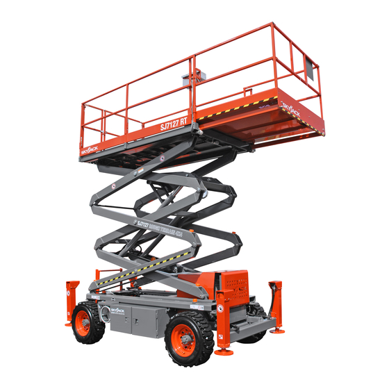
- Page 42 Major Components Section 3 - Operation 3.2 Major Components Entry Gate Platform Control Console Extension Platform Main Platform Maintenance Support Lifting Mechanism Hydraulic/ Electrical Engine Compartment Compartment Outrigger Base SKYJACK Model 7127 Aerial Platform Rough Terrain Scissors Page 42 December 2007...
- Page 43 Section 3 - Operation Major Assemblies 3.3 Major Assemblies 3.3-2 Lifting Mechanism The lifting mechanism is constructed of formed steel or The aerial platform consists of three major assemblies: tube sections making up a scissor-type assembly. The base, lifting mechanism and platform. scissor assembly is raised and lowered by single-acting 3.3-1 Base hydraulic lift cylinders with holding valves.
- Page 44 Component Identification Operation - Section 3 3.5 Component Identification WARNING The following descriptions are for identification, The maintenance support must be used explanation and locating purposes only. when inspection and/or maintenance or repairs are to be performed within the 3.5-1 Manual Storage Box lifting mechanism.
- Page 45 Section 3 - Operation Component Identification 3.5-4 Folding Guardrail System 3.5-5 Lanyard Attachment Anchorage This system, when folded down, reduces the height Use this as an attachment point for safety belt/harness of the retracted aerial platform for transporting and tethers. Do not attach belts/harnesses to any other point traveling through doorways only.
- Page 46 Component Identification (Special Options) Section 3 - Operation 3.6 Component Identification (Optional Leveling Indicator Light - This light functions when the auto and manual level functions are in Equipment/Attachments) use and illuminates to display the status of the This following descriptions are for identification, auto-leveling outriggers.
- Page 47 Section 3 - Operation Component Identification (Special Options) 3.6-3 1500W AC Inverter (If Equipped) The inverter is located on the base of the aerial platform. It has the following controls: Figure 3-8. 1500W AC Inverter NOTE The inverter operation is automatic. These controls do not need to be manipulated for normal operation.
- Page 48 Operator’s Responsibility Section 3 - Operation 3.7 Operator’s Responsibility Repairs to the aerial platform may only be made by a qualified service technician. After repairs are completed, It is the responsibility of the operator, prior to each work the operator must perform visual and daily maintenance shift, to perform the following: inspections &...
- Page 49 Section 3 - Operation Start Operation 3.8 Start Operation 3.8-1 To Activate Base Control Console Carefully read and completely understand the Operating Manual and all warnings and instruction labels (refer to WARNING Section 5 - Labels) on the aerial platform. Ensure that you maintain three points of contact when using the ladder to mount/ WARNING...
- Page 50 Start Operation Section 3 - Operation To start the engine: On base control console, pull out “ ” emergency stop button. • If dual fuel engine is cold, select and hold “ ” choke switch (if equipped) with engine WARNING “...
- Page 51 Section 3 - Operation Start Operation 3.8-4 To Raise or Lower Platform Using 3.8-5 To Drive Forward or Backward Platform Control Console WARNING WARNING Be aware of blind spots when operating Be aware of overhead obstructions or the aerial platform. other possible hazards around the aerial platform when lifting.
- Page 52 Start Operation Section 3 - Operation 3.8-6 To Steer 3.8-7 To Select Drive Torque Activate platform control console (refer to High Torque: Select high torque when ascending Section 3.8-3). or descending grades, traveling on rough terrain or when loading or unloading aerial platform. To activate high torque, select low/high speed range Select off/lift/drive key switch to “...
- Page 53 Section 3 - Operation Start Operation 3.8-8 To Extend or Retract Manual Extension 3.8-9 To Extend or Retract Powered Extension Platform Platform (If Equipped) To extend the powered extension platform, ensure “ ” emergency stop button is pulled out. On platform control console, insert key into off/lift/ drive key switch and select “...
- Page 54 Start Operation Section 3 - Operation 3.8-10 Hydraulic Outriggers (If Equipped) Ensure each outrigger pad is in firm contact over These devices are mounted to the four corners of the its entire surface area, with a suitable supporting base. surface! Make adjustments if necessary using manual outrigger controls.
- Page 55 Section 3 - Operation Start Operation 3.8-11 Generator (If Equipped) 3.8-13 Shutdown Procedure To start the hydraulic generator: Completely lower the platform. On platform control console, select off/lift/drive On platform control console, push in “ ” emergency stop button. key switch to “ ”...
- Page 56 Refueling Procedure Section 3 - Operation 3.9 Refueling Procedures 3.9-1 Regular Fuel (Gasoline or Diesel) This section provides the operator with the procedure Ensure engine and all systems are turned off and on how to refuel the engine with regular fuel and install emergency stop buttons are depressed.
- Page 57 Section 3 - Operation Refueling Procedure 3.9-2 Propane To install a propane cylinder: Ensure engine and all systems are turned off and WARNING emergency stop button is depressed. Follow all local and federal regulations for propane handling. Place propane cylinder on bracket or in compartment.
- Page 58 Loading/Unloading Section 3 - Operation 3.10 Loading/Unloading 3.10-1 Lifting Know and heed all national, state or territorial/provincial and local rules which apply to your loading/unloading WARNING of aerial platforms. Only qualified rigger shall operate machinery during lifting. Only qualified personnel shall operate machinery during loading/unloading.
- Page 59 • Aerial platform brake must be checked for proper The aerial platform can be lifted with a operation. forklift from the sides, but Skyjack does not • Aerial platform speed must be on high torque recommend this use, except for Models 92xx setting.
- Page 60 Guardrail Folding Procedure Section 3 - Operation 3.11 Guardrail Folding Procedure Turn main power disconnect switch to “ ” off When folded down, the folding guardrail system reduces position. the overall height of the retracted aerial platform for WARNING transporting only. Ensure that you maintain three points of contact when using the ladder to mount/ WARNING...
- Page 61 Section 3 - Operation Guardrail Folding Procedure Swing the right extension guardrail up and lock it in place by inserting all locking pins on the right extension. Swing the left extension guardrail up and lock it in place by inserting all locking pins. Remove the locking pins and swing the front guardrail forward.
- Page 62 Maintenance Support Procedure Section 3 - Operation 3.12 Maintenance Support Procedure To Store the Maintenance Support This section provides the operator with procedure regarding deployment and storage of maintenance Turn main power disconnect switch to “ ” on support. position. The maintenance support is a safety mechanism Raise platform until there is adequate clearance designed to support the scissor assembly.
- Page 63 Section 4 Tables Table 4.1 Standard and Optional Features Mid-Size RTs Full-Size RTs MODEL 7127 7135 8831 8841 9250 S T A N D A R D E Q U I P M E N T Base control Joystick control Dual range (torque/speed) selector Operator horn Diamond pattern, all steel platform deck construction...
- Page 64 Tables Section 4 Table 4.2 Owner’s Annual Inspection Record Model Number: _________________ Serial Number:__________________ 20__ 20__ 20__ 20__ 20__ 20__ 20__ 20__ 20__ 1000AA This decal is located on the scissor assembly. It must be completed after an annual inspection has been completed. Do not use the aerial platform if an inspection has not been recorded in the last 13 months.
- Page 65 Section 4 Tables Table 4.3 Specifications and Features Mid Size RTs Full Size RTs MODEL 7127 7135 8831 8841 9250 8,420 lb. 8,850 lb. 9,670 lb. 10,570 lb. 14,700 lb. Weight* 3819 kg 4014 kg 4386 kg 4794 kg 6668 kg 71.5”...
- Page 66 Tables Section 4 Table 4.4 Maximum Platform Capacities (Evenly Distributed) Tilt Total First Extension Second Extension Maximum Cutout MODEL Wind Number of Number of Number of Setting Capacity Capacity Capacity Speed Occupants Occupants Occupants (Degrees) 1500 lb. 500 lb. One Extension 12.5 m/s 2 x 4 Not Available...
- Page 67 Section 4 Tables Table 4.5 Maximum Platform Capacities (Evenly Distributed with Optional #7 Tires) Tilt Total First Extension Second Extension Maximum Cutout MODEL Wind Number of Number of Number of Setting Capacity Capacity Capacity Speed Occupants Occupants Occupants (Degrees) 1500 lb. 500 lb.
- Page 68 Tables Section 4 Table 4.6 Floor Loading Pressure Total Aerial Platform Load Total Aerial Platform Weight MODEL WHEEL LCP ** OUP ** kg/m min* 7920 3592 3168 1437 101.7 701.2 150.0 732.4 7127 max* 12180 5525 4872 2210 121.1 835.0 230.7 1126.4 min*...
- Page 69 Section 4 Tables Floor Loading Pressure Locally Concentrated Pressure (LCP): Overall Uniform Pressure (OUP): Foot Print Area = Length x Width Base Area = Length x Width = πr Weight of Aerial Platform + Capacity Weight of Aerial Platform + Capacity LCP = OUP = Foot Print Area x 4 (Tires)
- Page 70 Intermixing tires of different types or using tires of types other than those originally supplied with this equipment can adversely affect stability. Therefore, replace tires only with the exact Skyjack- approved type. Failure to operate with matched approved tires in good condition may result in death or serious injury.
- Page 71 B - Perform Scheduled Maintenance Inspection. Refer to Service & Maintenance manual. * - Maintenance must be performed only by trained and competent personnel who are familiar with mechanical procedures. † - Refer to Skyjack's website @ www.skyjack.com for latest service bulletins prior to performing quarterly or yearly inspection.
- Page 72 Powered Extension Control Console (If Equipped) Test Main Power Disconnect Switch Lifting Mechanism Test Outriggers (If Equipped) 60604AE-ANSI-R Note: Make a copy of this page or visit the Skyjack web site: www.skyjack.com for a printable copy. Rough Terrain Scissors Page 72 December 2007...
- Page 73 Section 5 Labels Label Legend Safety Red Safety Red indicates DANGER. Safety Orange Safety Orange indicates WARNING. Safety Yellow Safety Yellow indicates CAUTION. Safety Green Safety Green indicates emergency lowering. Safety Blue Safety Blue indicates safety information. Rough Terrain Scissors December 2007 Page 73...
- Page 74 Labels Section 5 Models 7127 & 7135 Left Side Front Side 124631AC 124631AC Electrical Panel and Hydraulic/Fuel Compartment 119674AD 117389-0 117387-0 117390AC Top View Radiator Mounting Plate Rough Terrain Scissors Page 74 December 2007...
- Page 75 Section 5 Labels Models 7127 & 7135 Back Side Right Side 33 34 PLATFORM CAPACITIES 400 N (90 lb) 12. 5 m/s (28 mph) 124362AB 124465AD 124631AC 124631AC 12 13 Hydraulic/Fuel Compartment Cylinder 36 37 Rough Terrain Scissors December 2007 Page 75...
- Page 76 Labels Section 5 Models 8831 & 8841 Right Side PROPANE Front Side Hydraulic/Fuel Compartment Cylinder Rough Terrain Scissors Page 76 December 2007...
- Page 77 Section 5 Labels Models 8831 & 8841 Left Side Back Side Electrical Panel and Hydraulic/Fuel Compartment 147197AA Rough Terrain Scissors December 2007 Page 77...
- Page 78 Labels Section 5 Model 9250 Left Side Front Side Electrical Panel and Hydraulic/Fuel Compartment 147197AA Rough Terrain Scissors Page 78 December 2007...
- Page 79 Section 5 Labels Model 9250 Right Side PROPANE Cylinder Back Side Fuel Compartment Rough Terrain Scissors December 2007 Page 79...
- Page 80 Labels Section 5 No. Label Pictorial Description Skyjack Logo Skyjack Caution Tape Stripe Caution stripe Tire Sealant (If Equipped) Indicates that tire sealant is present inside the tires. Wheel Load* Indicates rated wheel load. *Wheel load will vary with each model.
- Page 81 Section 5 Labels No. Label Pictorial Description Model Number* Product Identifier *Model number will vary, may not be as shown. Keep Clear Keep clear. Stay away from aerial platform when in operation. How to engage maintenance support for inspection or maintenance.
- Page 82 Labels Section 5 No. Label Pictorial Description Platform Capacity* Rated work load in each configuration is as shown. *Platform capacity varies over different aerial platforms. No Step WARNING! Do not step in this location. Main Power Disconnect Rotate clockwise to turn on main power; rotate counterclockwise to turn off main power;...
- Page 83 Section 5 Labels No. Label Pictorial Description Base Controls Select “ ” to lower or “ ” raise platform. Select “ ” to enable lift. Push “ ” to disable controls. Emergency Lowering Procedure Refer to operating manual. 1. Turn main power disconnect switch to off position. 2.
- Page 84 Labels Section 5 No. Label Pictorial Description Annual Inspection Ensure that work platform has received annual inspection prior to operation. Hazard Identification Refer to Section 1: Safety Rules. Read and understand the outlined risks associated with this work platform prior to operation.
- Page 85 Section 5 Labels No. Label Pictorial Description Liquid Propane Use liquid propane only. No Smoking Do not smoke near this location. Diesel Ultra Low Sulfur Only Diesel Ultra Low Sulfur Only Diesel Use low sulfur fuel or ultra low sulfur fuel only. Unleaded Fuel Use unleaded gasoline only.
- Page 86 Labels Section 5 Outriggers Engine Control Console Rough Terrain Scissors Page 86 December 2007...
- Page 87 Section 5 Labels No. Label Pictorial Description Keep Clear Stay away from aerial platform when in operation. Crushing Hazard Danger - crushing hazard Warning - Do Not Alter Do not alter or disable limit switches or other safety devices. Engine Control - Kubota Diesel Select “...
- Page 88 Labels Section 5 Railing Pins Air Line to Platform Lanyard Anchorage Welder Tray 100 PSI 6.9 BAR 138212AA No. Label Pictorial Description Lanyard Anchorage Point Attach anchorage harness lanyard here. Welder Mounting Location CAUTION Welder and tray must be located within boundary of guard rails. Welder and tray must be located within the boundry Tray must be mounted on midrail and one vertical post to restrict of guard rails.
- Page 89 Section 5 Labels Platform Control Console No. Label Pictorial Description Controller Operation Squeeze “ ” trigger to enable controller. Operate “ ” rocker switch to steer. Move controller forward “ ” to drive forward or backward “ ” to drive reverse.. Low/High Speed Range Select “...
- Page 90 Labels Section 5 No. Label Pictorial Description Off/Lift/Drive Select “ ” off, “ ” lift or “ ” drive mode. Emergency Stop Push to disable controls Lift Enable Select to enable lift mode. Start Engine Select to start engine. Glow Plug Select to activate glow plugs.
- Page 91 Section 5 Labels Auxiliary Control Consoles No. Label Pictorial Description Powered Extension Platform Enable Select to enable powered extension platform controls. Powered Extension Platform Extend/Retract Select “ “ to extend or “ “ to retract powered extension platform. Outrigger Controls with Generator Select “...
- Page 92 Notes Rough Terrain Scissors Page 92 December 2007...
- Page 93 California Proposition 65 Engine exhaust and some of its constituents are known to the State of California to cause cancer, birth defects, and other reproductive harm. Battery posts, terminals, and related accessories contain lead and lead com- pounds, chemicals known to the State of California to cause cancer, birth defects, and other reproductive harm.
- Page 94 Pålitelig lift løsninger av folk som bryr seg. www.skyjack.com...
Need help?
Do you have a question about the SJ7127 RT and is the answer not in the manual?
Questions and answers
Pump won’t engage to raise outriggers
The pump may not engage to raise the outriggers on the Skyjack SJ7127 RT due to the following reasons:
1. The outriggers are not extended enough to take the weight off the tires.
2. There is a loose or broken wire #10A between terminal block TB2 and pin #4 on connector CN14 at the outrigger board.
3. There is a loose or broken wire #10A between the outrigger board and outrigger limit switch LS68.
4. The outrigger limit switch LS68 is defective.
5. There is a loose or broken wire #68A between LS68 and the outrigger control module at pin P2-1.
6. There is a loose or broken wire #10A between the outrigger board and outrigger limit switch LS67.
7. The outrigger limit switch LS67 is defective.
Each of these issues can prevent the system from detecting that the outriggers are properly extended, which can stop the pump from engaging.
This answer is automatically generated