Sign In
Upload
Download
Table of Contents
Contents
Add to my manuals
Delete from my manuals
Share
URL of this page:
HTML Link:
Bookmark this page
Add
Manual will be automatically added to "My Manuals"
Print this page
×
Bookmark added
×
Added to my manuals
Manuals
Brands
Skyjack Manuals
Scissor Lifts
SJ8831 RT
Operating manual
Skyjack SJ8831 RT Operating Manual
Rough terrain scissors
Hide thumbs
Also See for SJ8831 RT
:
Operating manual
(95 pages)
1
2
3
Table Of Contents
4
5
6
7
8
9
10
11
12
13
14
15
16
17
18
19
20
21
22
23
24
25
26
27
28
29
30
31
32
33
34
35
36
37
38
39
40
41
42
43
44
45
46
47
48
49
50
51
52
53
54
55
56
57
58
59
60
61
62
63
64
65
66
67
68
69
70
71
72
73
74
75
76
77
78
79
80
81
82
83
84
85
86
87
88
page
of
88
Go
/
88
Contents
Table of Contents
Bookmarks
Table of Contents
Table of Contents
Section 1 - about Your Aerial Platform
Read and Heed
Safety Rules
Section 2- Familiarization
Familiarization of SJRT MID Size and Full Size Series
Component Identification
Visual & Daily Maintenance Inspections
Function Tests
Winching and Towing Procedure
Emergency Lowering Procedures
Section 3 - Operation
General
Major Components
Major Assemblies
Serial Number Nameplate
Component Identification
Component Identification (Optional Equipment/Attachments)
Operator's Responsibility
Start Operation
Refueling Procedure
Loading/Unloading
Guardrail Folding Procedure
Maintenance Support Procedure
Section 4 - Tables
Section 5 - Labels
Advertisement
Quick Links
1
Table of Contents
2
Section 1 - about Your Aerial Platform
3
Winching and Towing Procedure
4
Section 3 - Operation
5
General
6
Start Operation
7
Maintenance Support Procedure
8
Section 4 - Tables
Download this manual
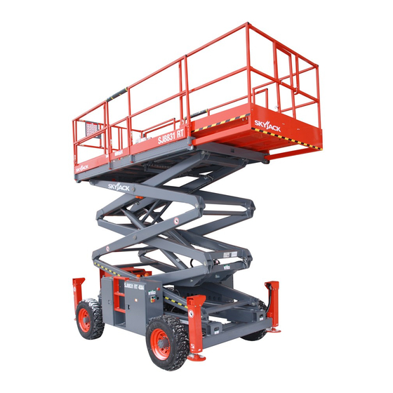
OPERATING MANUAL (CE)
ROUGH TERRAIN SCISSORS
MODELS
SJ8831 RT SJ8841 RT SJ9241 RT SJ9250 RT
159149AC-A
August 2014
Table of
Contents
Previous
Page
Next
Page
1
2
3
4
5
Advertisement
Table of Contents
Need help?
Do you have a question about the SJ8831 RT and is the answer not in the manual?
Ask a question
Questions and answers
Related Manuals for Skyjack SJ8831 RT
Scissor Lifts Skyjack SJ7127 RT Operating Manual
Rough terrain scissors (95 pages)
Scissor Lifts Skyjack Rough Terrain 800E Series Operating Manual
Ansi/csa (77 pages)
Scissor Lifts Skyjack SJ3220 Service Manual
Dc electric scissors (177 pages)
Scissor Lifts Skyjack SJIII 3219 Operating Manual
Dc electric scissors (104 pages)
Scissor Lifts Skyjack SJIII 4620 Operating Manual
Dc electric scissors (108 pages)
Scissor Lifts Skyjack SJIII 3220 Service Manual
(150 pages)
Scissor Lifts Skyjack SJ6826RT Service Manual
Rough terrain scissors (177 pages)
Scissor Lifts Skyjack SJ7127 RT Service Manual
Rough terrain scissors (154 pages)
Scissor Lifts Skyjack SJ6832 RTE Operating Manual
Rough terrain scissors (96 pages)
Scissor Lifts Skyjack SJ6832 RTE Operation Manual
Rough terrain scissors (112 pages)
Scissor Lifts Skyjack SJ9664 RT Operation Manual
(122 pages)
Scissor Lifts Skyjack SJIII Series Maintenance & Parts Manual
(207 pages)
Scissor Lifts Skyjack SJIII Series Maintenance & Parts Manual
(221 pages)
Scissor Lifts Skyjack SJM Series Operating Manual
(49 pages)
Scissor Lifts Skyjack SJ519 TH Operating Manual
(100 pages)
Scissor Lifts Skyjack SJ3215 E Operation Manual
Dc electric scissors (128 pages)
This manual is also suitable for:
Sj8841 rt
Sj9241 rt
Sj9250 rt
Table of Contents
Print
Rename the bookmark
Delete bookmark?
Delete from my manuals?
Login
Sign In
OR
Sign in with Facebook
Sign in with Google
Upload manual
Upload from disk
Upload from URL


Need help?
Do you have a question about the SJ8831 RT and is the answer not in the manual?
Questions and answers