Sign In
Upload
Manuals
Brands
Skyjack Manuals
Scissor Lifts
SJ7127 RT
Skyjack SJ7127 RT Manuals
Manuals and User Guides for Skyjack SJ7127 RT. We have
2
Skyjack SJ7127 RT manuals available for free PDF download: Service Manual, Operating Manual
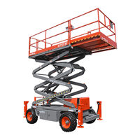
Skyjack SJ7127 RT Service Manual (154 pages)
ROUGH TERRAIN SCISSORS
Brand:
Skyjack
| Category:
Scissor Lifts
| Size: 15.89 MB
Table of Contents
1 Section 1 Scheduled Maintenance
5
Table of Contents
5
Operator's Responsibility for Maintenance
6
Aerial Platform and Mobile Elevating Work Platform Definition
6
Manuals
6
Operator Safety Reminders, Warnings, and Precautions
6
Purpose of Equipment
6
Service Policy and Warranty
6
Use of Equipment
6
Maintenance and Inspection Schedule
7
Maintenance and Service Safety Tips
7
Owner's Annual Inspection Record
7
Replacement Parts
7
Hydraulic System & Component Maintenance and Repair
8
Maintenance Hints
8
About this Section
9
Maintenance and Inspection
9
Maintenance Instructions
9
Scheduled Maintenance
9
Service and Maintenance
9
Service Bulletins
9
Tables
10
Scheduled Maintenance
10
Table 1.1 Owner's Annual Inspection Record
10
Table 1.2 Pre-Delivery/Maintenance Inspection Checklist
11
Scheduled Maintenance Inspections
12
Function Tests
24
Section 2 Maintenance Tables and Diagrams
25
Table of Contents
25
Section 3 System Component Identification and Schematics
37
Charts
38
Hydraulic Symbol Chart
38
Electrical Symbol Chart
39
AC Cord Colour Code
40
Parts List
41
Hydraulic Component Parts List
41
Electrical Component Parts List
43
Platform Control Console Diagram - All Options (ANSI/CSA)
48
Diagrams and Schematics
49
Control Cable Assemblies Diagram
49
Outrigger/Hydraulic Generator Control Console Wiring Diagram
50
Electrical Inverter Wiring Diagram
51
Hydraulic Schematic
53
Hydraulic Manifold Components and Port Identifications
54
Main Manifold / Cabinet Harness Wiring Diagram (ANSI/CSA)
55
Electrical Panel Wiring Diagram (ANSI/CSA)
56
Electrical Panel Harnesses Wiring Diagram
58
Horn, Light & Beeper Wiring Diagram (ANSI/CSA)
59
Powered Extension Related Assemblies & Electrical Wiring Diagram
60
Lift Cylinder Holding Valve Harness Connection Diagram
61
Engine Harness Wiring Diagram - Diesel Fuel System (Kubota Engine)
62
Engine Harness Wiring Diagram - Dual Fuel System (Kubota Engine)
63
Oil Cooler Electrical Panel Diagram
64
Hydraulic Generator Electrical Panel Diagram
65
12Kw Generator Electrical Panel Diagram - Modification (Model 71Xx)
66
12Kw Generator Hydraulic and Electric Wiring Schematics (Model 71Xx)
67
Outrigger Option Electrical Diagram (ANSI/CSA)
68
Telematics Harness Wiring Diagram
69
Electric Panel with Positive Air Shut off Option (Model 71Xx)
70
Positive Air Shut off Harness Wiring Diagram - Diesel Engine
71
Electrical Schematic - Kubota Diesel Engine All Options (ANSI/CSA)
72
Electrical Schematic - Kubota Dual Fuel Engine All Options (ANSI/CSA)
73
Section 4 Troubleshooting Information
75
Electrical System
78
All Controls Inoperative
78
No Power to Platform (ANSI/CSA)
78
All Functions Inoperative from Platform
78
Engine will Not Crank from Platform
79
Engine will Not Crank from Base Controls (Kubota Diesel)
79
Engine will Not Crank from Base Controls (Kubota Dual Fuel)
80
Engine Cranks but Stops Cranking after a few Seconds
80
Glow Plugs Inoperative from Engine Controls
80
Glow Plugs Inoperative from Platform (Additional)
80
10 Engine Cranks but will Not Start (Kubota Diesel)
81
11 Engine Cranks but will Not Start (Kubota Dual Fuel)
81
12 High Throttle on Demand Inoperative (Kubota Dual Fuel)
82
13 High Throttle Inoperative
82
14 Drive and Steer Inoperative (Machines Without Outriggers Option)
83
15 Drive and Steer Inoperative (Machines with Outriggers Option)
84
16 Brakes will Not Release
85
17 Steer Right Inoperative
85
18 Steer Left Inoperative
86
19 Reverse Drive Inoperative
86
20 Forward Drive Inoperative
87
21 First Drive Speed and Steering Inoperative
87
22 Second Drive Speed Inoperative
88
23 Third Drive Speed Inoperative
89
24 High/Low Range Speed Inoperative
89
25 Up Circuit Inoperative from Platform or Base (Machines Without Outriggers)
90
26 Up Circuit Inoperative from Base (ANSI/CSA)
91
27 Platform will Not Lift from Platform or Base Controls with Outriggers Retracted
91
28 Platform will Not Lift from Platform or Base Controls with Outriggers Extended
92
29 Down Circuit Inoperative from Platform or Base
93
30 Down Circuit Inoperative from Base
94
31 Powered Extension Platform Inoperative
94
32 Powered Extension Platform will Not Extend
94
33 Powered Extension Platform will Not Retract
95
34 Hydraulic Generator Inoperative
95
35 Hydraulic Generator will Not Shut off from Generator Switch
96
36 All Outriggers Inoperative (Auto-Level and Manual)
96
37 All Outriggers Inoperative (Auto-Level and Manual from Platform Controls)
97
38 All Outriggers Inoperative (Base Controls)
97
39 All Outriggers Inoperative (Auto-Level) A: Led Power Indicator Light at Outrigger Control Module OCM1 Not on Constant
97
40 All Outriggers Inoperative (Auto Level) B: Led Power Indicator Light at Outrigger Control Module (OCM1) Flashing
98
41 Left Front Outrigger Inoperative Manually
99
42 Right Front Outrigger Inoperative Manually
99
43 Right Rear Outriggers Inoperative Manually
99
44 Left Rear Outriggers Inoperative Manually
100
45 Individual Outrigger Functions Inoperative (Auto-Level)
100
46 Auto-Level Inoperative
100
47 Auto All up Inoperative (Retract)
101
Hydraulic System
102
All Functions Inoperative
102
Steering Inoperative
102
Lift, Steer and First Drive Speed Inoperative
102
Second Drive Speed Inoperative
102
Drive Inoperative
102
Reverse Drive Inoperative
103
Forward Drive Inoperative
103
Brakes will Not Release
103
Up Circuit Inoperative
103
10 Down Circuit Inoperative
103
11 Powered Extension Platform Inoperative
104
12 Hydraulic Generator Inoperative
104
13 All Outriggers Inoperative
104
14 Left Front Outrigger Inoperative
104
15 Right Front Outrigger Inoperative
104
16 Right Rear Outrigger Inoperative
105
17 Left Rear Outrigger Inoperative
105
18 Outriggers Drift in
105
Section 5 Procedures
107
Base
108
Brake Caliper Adjustment
108
General
108
Hydraulic System
108
Safety and Workmanship
108
Bleeding the Brake Caliper
110
Changing the Hydraulic Oil
112
Wheel Bolt/Nut Inspection and Torquing Procedure
112
Wheel Reinstallation and Torquing Procedure
113
Front Axle Hub Procedure
114
Electronic Tilt Switch Setup Procedure
116
Reconnecting the Platform Control Box for Use from the Ground
120
Tightening and Torque Recommendations for Hydraulic Couplings and Hoses
121
10 Checking the Holding Valve
122
11 System Pressure Setting
123
12 Lift Pressure Setting
124
13 Grease Points
125
Engines
126
Kubota Dual Fuel (DF972) Resistance Checks
126
Kubota Dual Fuel (DF972) Engine Throttle Setting
127
Kubota Diesel (D1105/1305) Engine Throttle Setting
129
Fan Belt Replacement and Adjustment
131
Replacing the Air Cleaner Element
132
Bleeding the Fuel System of Air (Kubota D1105/1305)
133
Replacing the Fuel Filter Element (Kubota D1105/1305)
133
Changing the Oil
134
Replacing the Oil Filter Cartridge
134
10 Checking and Replenishing the Radiator Coolant Level
135
11 Draining and Refilling the Radiator
135
Auto-Leveling Outrigger PC Board Layout
136
Outriggers
136
Outrigger Mechanical Limit Switch Wiring Diagram
137
Auto-Leveling Outrigger Setting and Error Codes
138
Auto-Leveling Outrigger Error Code Breakdown
139
Hand Held Calibration/Diagnostic Tool Key Functions
140
Outrigger Control Module Instructions
141
Auto-Leveling Outrigger Control Module Pin Reference Chart
144
Outrigger Upper Limit Switch (LS61, LS62, LS63, LS64) Replacement and Adjustment
145
Outrigger Lower Limit Switch (LS65, LS66, LS67, LS68) Replacement and Adjustment
146
High Speed Cutout (LS5) and End of Stroke (LS4) Limit Switch Replacement and Adjustment
148
Scissors
148
Gate Springe Hinge Adjustment
150
Platform
150
Advertisement
Skyjack SJ7127 RT Operating Manual (95 pages)
ROUGH TERRAIN SCISSORS
Brand:
Skyjack
| Category:
Scissor Lifts
| Size: 24.09 MB
Table of Contents
Table of Contents
4
Section 1 - about Your Aerial Platform
5
Read and Heed
5
Safety Rules
6
Safety Rules
7
Electrocution Hazard
7
Section 2- Familiarization
13
Familiarization of SJRT MID Size and Full Size Series
13
Component Identification
14
Main Power Disconnect Switch
14
Tilt Alarm
14
Base Control Console
14
Brake System
15
Propane Cylinder
15
Emergency Lowering System
15
Engine Control Console
16
Platform Control Console
17
Visual & Daily Maintenance Inspections
18
Hydraulic/Fuel Compartment
21
Engine Compartment
22
Platform Assembly
24
Lifting Mechanism
25
Base
26
Function Tests
28
Test Emergency Stop
29
Test Lift Enable
29
Test Platform Raising/Lowering
30
Test Steering
30
Test Enable Trigger Switch
30
Test Driving
31
Test Brake
31
Test Speed Limit
32
Test Powerdeck Enable
32
Test Extension Platform
32
Test Lower/Neutral/Raise Switch
33
Test Base Lift Enable
33
Test Emergency Lowering
34
Test Main Power Disconnect Switch
34
Winching and Towing Procedure
38
To Release the Brake Manually
38
Emergency Lowering Procedures
39
Section 3 - Operation
41
General
41
Major Components
42
Product View
42
Major Assemblies
43
Serial Number Nameplate
43
Manual Storage Box
44
Maintenance Support
44
Electrical Control Console
44
Component Identification
44
Folding Guardrail System
45
Lanyard Attachment Anchorage
45
AC Outlet on Platform
45
Component Identification (Special Options)
46
1500W AC Inverter
47
Visual and Daily Maintenance Inspections
48
Operator's Responsibility
48
Start Operation
49
To Activate Base Control Console
49
To Raise or Lower Platform Using Base Control Console
50
To Activate Platform Control Console
50
To Raise or Lower Platform Using Platform Control Console
51
To Drive Forward or Backward
51
To Steer
52
To Select Drive Torque
52
To Extend or Retract Manual Extension Platform
53
To Extend or Retract Powered Extension Platform
53
Hydraulic Outriggers
54
To Extend Outriggers
54
To Retract Outriggers
54
Auto Retraction
54
Generator
55
Electrical Inverter
55
Shutdown Procedure
55
Refueling Procedures
56
Regular Fuel (Gasoline or Diesel)
56
Propane
57
To Install a Propane Cylinder
57
Loading/Unloading
58
Lifting
58
Driving
59
Guardrail Folding Procedure
60
Maintenance Support Procedure
62
To Store the Maintenance Support
62
Standard and Optional Features
63
Section 4 - Tables
63
Specifications and Features
65
Maximum Platform Capacities
66
Floor Loading Pressure
68
Locally Concentrated Pressure (LCP)
69
Overall Uniform Pressure (OUP)
69
Tire Specifications
70
Maintenance and Inspection Schedule
71
Section 5 - Labels
73
Advertisement
Related Products
Skyjack SJ7135 RT
Skyjack SJ 68RT Series
Skyjack SJ8831 RT
Skyjack SJ8841 RT
Skyjack SJM 32261
Skyjack SJII 3220
Skyjack SJII 32261
Skyjack SJII 6626
Skyjack SJ519 TH
Skyjack SJ9664 RT
Skyjack Categories
Lifting Systems
Boom Lifts
Scissor Lifts
Forklifts
Battery Charger
More Skyjack Manuals
Login
Sign In
OR
Sign in with Facebook
Sign in with Google
Upload manual
Upload from disk
Upload from URL