
Subscribe to Our Youtube Channel
Related Manuals for Prostat PRS-812


Summary of Contents for Prostat PRS-812
- Page 1 P R O F E S S I O N A L S T A T I C C O N T R O L P R O D U C T S Resistance Meter PRS-812 Operations Manual...
- Page 2 Copyright 2001-2009 by PROSTAT Corporation. All rights reserved. Printed in the United States of America. No part of this manual may be used or reproduced in any manner whatsoever without written permission. For information contact PROSTAT Corporation, 1072 Tower Lane, Bensenville, IL 60106...
-
Page 3: Table Of Contents
PRS-812 Resistance Meter TABLE OF CONTENTS ® PROSTAT PRS-812 RESISTANCE METER Title Page # Introduction & Description ....................2 Cautions & Warnings ....................... 5 III. Controls, Connections & Indicators ................. 7 Setup & Calibration ......................13 Instrument Operation ..................... 15 Instrument Maintenance .................... -
Page 5: Introduction & Description
1.0 and 1.0x10 ohms are within 0.5% of laboratory references. While quite sophisticated in design, the PRS-812 Resistance Meter is easy to use and extremely helpful in making accurate ESD auditing measurements, or general resistance and continuity checks. - Page 6 6. One Metal Test Plate (PRS-800-MTL) 7. One calibration shunt for low range adjustment (PRS-801 CC) Optional accessories are available for the PROSTAT PRS-812 Resistance Meter. Refer to PROSTAT’s current brochure or web site (www.prostatcorp.com) for additional information. C. PRS-812 Basic Description & Functions...
-
Page 7: Cautions & Warnings
II. Cautions & Warnings A. As with any electrical device, use proper safety precautions and safe measurement procedures to avoid personnel shock and arc discharge. B. The PRS-812 Resistance Meter is battery operated and delivers test voltages up to 100 volts. - Page 8 PRS-812, particularly at 100 volts. D. Although the PRS-812 is current limited, a distinct hazard exists in the person’s reaction to a potential shock. E. To avoid personnel shock, follow the General Operations instructions at all times. Do not touch energized electrodes or fixtures when power is applied except as specifically described in this and accessory instructions.
-
Page 9: Controls, Connections & Indicators
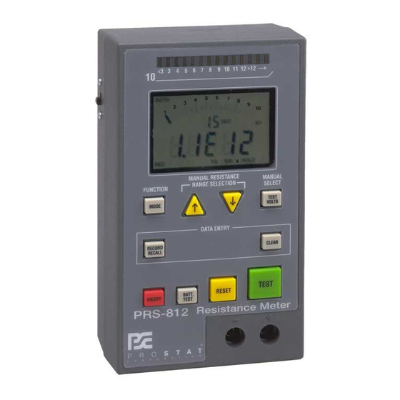
Unauthorized opening of the PRS-812 case or dismantling in any manner WILL VOID THE INSTRUMENT’S WARRANTY. 4. Read this manual in its entirety before installing batteries or using the PRS-812. 5. Do not drop or cause unnecessary mechanical shock to your PRS-812 instrument 6. - Page 10 PRS-812 Resistance Meter Figure 2: PRS-812 Controls & Display Indicators PRS-812 Controls [1] FUNCTION/ MODE Toggles through Six Operation Modes (1) AUTO: (AUTOMATIC) displays data in exponential format 1.0EXX NOTE: AUTO in exponential format, e.g., 1.3E05, is the Default start up mode when the instrument is turned ON.
- Page 11 Third Press RECALL: Displays MAX Data Point in Memory Note: When displayed, [Over Level] indicates measurement greater than (>) 2.0x10 ohms, which is beyond the measurement capability of the PRS-812. Fourth Press RECALL: Displays AVG of all Memory Data Points...
- Page 12 PRS-812 Resistance Meter Note: OL [Over Level] measurements [>2.0x10 ohms] are not included in displayed average (AVG) calculation. Fifth Press RECALL: Returns System to normal operations Note: If in RECALL mode, pressing RESET will return the instrument to normal measurement operations.
- Page 13 Display Elements [11] Colored LED’s 14 LED’s across the top of the PRS-812 indicate measurement order of magnitude in decades from <10 to >10 + ohms. NOTE: The PRS-812 provides very accurate measurements up to 1.0x10 ohms, and has the capability to “indicate”...
- Page 14 PRS-812 Resistance Meter Displayed when RECALL button is pushed first time while in REC mode. Number displayed when MIN is indicated is the Minimum data value in Memory Register. Displayed when RECALL button is pushed a second time (sequentially) in REC mode.
-
Page 15: Setup & Calibration
PRS-812 Resistance Meter Cover Position Screws Leads Neatly Battery Buss Figure 3: Opening Battery Compartment. Figure 4: Install 2 each 9V Batteries Setup & Calibration A. Battery Installation (See Figures 3 & 4) 1. Position Battery Buss Cut Off switch to OFF position 2. - Page 16 Figure 6: Start the Calibration Sequence by Pressing RESET then CLEAR within ½ 7. Remove the calibration shunt from the lead terminals Second 8. The PRS-812 is now ready for wide range measurements from 0.1 to 1.0E+12 Ohms...
-
Page 17: Instrument Operation
1.02 Ohms 0.02 Ohms I nstrument O peration A. Overview of PRS-812 Operation & Measurement Test Cycle Sequence The following 10 points provide an overview for calibrating and using the PRS-812 for resistance measurements. 1. Slide Battery Buss Cut Off switch to ON 2. - Page 18 2.0x10 ohms. However, the user should be aware that accuracy degrades rapidly above 1.0x10 ohms. 8. When the PRS-812 displays and holds the final resistance measurement, HOLD is indicated in the lower, right corner of the LCD.
- Page 19 PRS-812 Resistance Meter The PRS-812 is processor controlled to obtain hundreds of measurements per second, and to make rapid adjustments in resistance range and test voltage as necessary. It will display the resistance measurement of the material under test based on the following criteria: A digital numeric display is the averaged result of eight (8) individual, consecutive measurements, each within 5% of each other...
- Page 20 As with most very precise instruments, the PRS-812 circuits and its cables are sensitive to the effects of electromagnetic and electrostatic fields. These effects, are minimized by instrument and test lead design and material selection.
- Page 21 AUTO Mode 2: Auto Display in , K, M, G and T indicators AUTO Mode 1 is the default functional mode when the PRS-812 is powered up. To change to AUTO Mode 2, simply press the MODE button once. The AUTOMATIC modes are used in measurements where the following attributes are desired: ...
- Page 22 3. Press the Red ON/OFF button to power up the instrument. (See Figure 1) 4. AUTO is displayed in the LCD. (See Figure 2) a. The default Mode for the PRS-812 is Automatic Resistance Measurement in Exponential Format. (1.0EXX). See Figure 2.
- Page 23 <10 volts to be applied to the Positive (+) Lead Terminal. The electrification timer will start counting seconds. Figure 9: PRS-812 Powered Up in AUTO Exponential Mode (Right). To change to Ohms Data Display Press Function Mode button once. (Left)
- Page 24 Measurement Is Complete Indicators Indicators Is Complete Figure 10: Comparing PRS-812 Display in Automatic Ohms Mode and Automatic Exponential Mode after the same low resistance measurement. 8. Measurements from 1.0x10 to less than 1.0x10 ohms: a. When the resistance measurement is Electrification Remains 2.0 –...
- Page 25 Once a stable measurement is confirmed and displayed by the instrument, HOLD will be displayed in the LCD and the electrification timer will stop. NOTE: The PRS-812 provides very accurate measurements up to 1.0x10 ohms, and has the capability to display values up to 2.0x10 ohms.
- Page 26 PRS-812 Resistance Meter c. Once the instrument confirms a stable measurement, if any, HOLD will be displayed in the LCD and the electrification timer will stop. If a stable measurement cannot be obtained at this range OL will be displayed.
- Page 27 (5) Pressing TEST will start a new Measurement Test Cycle 7. If the resistance you are measuring is higher than the decade that the PRS-812 is set for OL (Over Level) will be displayed. To move the selected resistance range up to a higher decade: a.
- Page 28 When AUTOMATIC electrification period and Test Voltage control must be maintained to current industry (and Automatic Mode) settings This mode prevents the PRS-812 from resetting the Test Voltage and Resistance Range to Minimum for each Measurement Test Cycle. In this mode, measurements start at the resistance range selected by the operator, and its commensurate Test Voltage.
- Page 29 G. The Memory Register: Data Logging & Calculation As previously described, the PRS-812 Resistance System will acquire and store up to 80 measurements, or data points, in its Memory Register when Record (REC) is activated.
-
Page 30: Instrument Maintenance
Instrument Maintenance A. Calibration & Repair 1. Instrument Calibration should be performed annually 2. Only Prostat Corporation or their authorized instrument laboratory should perform PRS- 812 calibration or repair. 3. Before shipping instrument to Prostat Corporation (USA) for service, contact Prostat calibration &... -
Page 31: Warranty Information
Limit of Liability – in no event will PROSTAT or any seller be responsible or liable for special, incidental, or consequential losses or damages, under any legal theory including but not limited to contract, negligence, or strict liability. - Page 32 (630) 238-9717 C. Shipping Non-Warranty Items 1. Any PROSTAT product returned for non-warranty repair or calibration requires a Return Materials Authorization (RMA) number and should be packaged and shipped as described above, and as directed by PROSTAT’s customer service department.
-
Page 33: Instrument Controls
PRS-812 Resistance Meter Register stores up to 80 data points (MEM # Displayed after RESET) Response & Response from >0.1 to <1.0E06 Ohms: <2.0 seconds Electrification: Average Measurement Period from 0.1 ohms to 1.0E12 Ohms 2.5 Seconds. Calculated Electrification Period per ESD S11.11, 7.5 second 0.1 ohms to 10E+12 Ohms. - Page 34 Displays GOOD on LCD if acceptable voltage or Lo if unacceptable Reset Enters (saves) data into Memory Register, Clears HOLD and Display. Test Begins measurement sequence. Battery Buss ON/OFF Switch isolates batteries from instrument circuits for storage & Cut Off transport Rev: PRS-812 – 4-2009 Format modification: 05-24-2005...
- Page 36 Copyright 2001-2009, Prostat Corporation Printed in U.S.A. 1072 Tower Lane, Bensenville, IL 60106 USA www.prostatcorp.com...
Need help?
Do you have a question about the PRS-812 and is the answer not in the manual?
Questions and answers