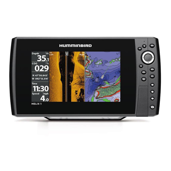
Humminbird HELIX Series Installation Diagrams
Hide thumbs
Also See for HELIX Series:
- Installation manual ,
- Operation manual (330 pages) ,
- Installation diagrams (10 pages)
Advertisement
Quick Links
BOW UNIT
Networking
Graph
1
2
CONSOLE UNIT
3
Networking
Graph
1
4
5
Cranking
Transducer supplied with
Battery
MEGA Side Imaging unit at
INSTALLATION DIAGRAMS
Console & Bow Mount Humminbird Units
The following schematic outlines the necessary
accessories/cables needed to connect two
Humminbird units. Installation is shown with a GPS/
heading sensor and additional High Speed Transducer.
HELIX Series
1
Ethernet Adapter Cable (need 2)
720074-1
2
Ethernet Cable (need 1)
720073-6
720073-2
720073-5
720073-3
720073-4
3
GPS + Heading Sensor
408400-1
4
Transducer Splitter Cable
720101-1
5
High Speed Transducer (fiberglass hull)
710276-1
High Speed Transducer (aluminum hull)
710274-1
NMEA 0183
The accessories and part numbers listed above are valid as of July 2019. Installations shown
are for networking HELIX
console
Compatible Accessories
Ethernet Adapter Cable
AS EC QDE
NA
Ethernet Cable (need 1)
AS EC 5E (5')
720073-6
AS EC 10E (10')
720073-2
AS EC 15E (15')
720073-5
AS EC 20E (20')
720073-3
AS EC 30E (30')
720073-4
GPS + Heading Sensor
AS GPS HS
408400-1
720080-1
Transducer Splitter Cable
9 M SIDB Y
720103-1
High Speed Transducer (fiberglass hull)
XP 9 HW T
710287-1
High Speed Transducer (aluminum hull)
XNT 9 HW T
710285-1
Ethernet
12V DC Power
Series or SOLIX
Series models.
®
®
SOLIX Series
AS EC 5E (5')
AS EC 10E (10')
AS EC 15E (15')
AS EC 20E (20')
AS EC 30E (30')
AS GPS HS
AS GPS NMEA
14 M SIDB Y
XP 14 HW T
XNT 14 HW T
Transducer Cable
Advertisement

Related Manuals for Humminbird HELIX Series


Summary of Contents for Humminbird HELIX Series
- Page 1 INSTALLATION DIAGRAMS Console & Bow Mount Humminbird Units The following schematic outlines the necessary accessories/cables needed to connect two BOW UNIT Humminbird units. Installation is shown with a GPS/ heading sensor and additional High Speed Transducer. Networking Graph Compatible Accessories...
-
Page 2: Installation Diagrams
Transducer supplied with Battery MEGA Side Imaging unit at The accessories and part numbers listed above are valid as of July 2019. Installations shown console are for networking HELIX Series or SOLIX Series models, and Minn Kota trolling motors with i-Pilot Link. - Page 3 * One (1) AS EC 30E 30’ ethernet cable included with trolling motor The accessories and part numbers listed above are valid as of July 2019. Installations shown are for networking HELIX Series or SOLIX Series models, and Minn Kota trolling motors with i-Pilot Link.
- Page 4 * One (1) AS EC 30E 30’ ethernet cable included with trolling motor MEGA Side Imaging unit at console The accessories and part numbers listed above are valid as of July 2019. Installations shown are for networking HELIX Series or SOLIX Series models, and Minn Kota trolling motors with i-Pilot Link.
- Page 5 Saltwater - Minn Kota Riptide Trolling Motor with i-Pilot Link and (1) Console Mount Humminbird Unit The following schematic outlines the necessary accessories/cables needed to connect one Humminbird unit and a Minn Kota trolling motor. Installation is shown with an optional GPS/heading sensor. Heading Sensor...
- Page 6 Link and (2) Console Mount Humminbird Units The following schematic outlines the necessary accessories/cables needed to network two Humminbird units and a Minn Kota Riptide trolling motor. Installation is shown with a GPS/heading Heading sensor and High Speed Transducer.
Need help?
Do you have a question about the HELIX Series and is the answer not in the manual?
Questions and answers