Neoway N720 Hardware User's Manual
Hide thumbs
Also See for N720:
- User manual (33 pages) ,
- User manual (9 pages) ,
- Hardware user's manual (94 pages)
Table of Contents
Advertisement
Advertisement
Table of Contents

Related Manuals for Neoway N720


Summary of Contents for Neoway N720
- Page 1 N720 Hardware User Guide () N720 Hardware User Guide Version 1.6...
- Page 2 Shenzhen Neoway provides customers complete technical support. If you have any question, please contact your account manager or email to the following email addresses: Sales@neoway.com...
- Page 3 2017-07 Modified the description of the PWRKEY and RESET pins Updated variants and bands Added SDIO, PCM, and I2C V1.6 Dong Liuting 2018-01 Added GNSS parameters Modified some description Copyright © Neoway Technology Co., Ltd...
-
Page 4: Table Of Contents
N720 Hardware User Guide Contents 1 Introduction to N720 ......................1 1.1 Overview ............................1 1.2 Block Diagram ........................... 2 1.3 Features .............................. 3 2 Application Interfaces ...................... 5 2.1 Specifications and Pin Definition ....................... 5 2.2 Pin Description ........................... 6 2.3 Power Control Interfaces ........................ - Page 5 6.2 PCB Foot Print ..........................46 7 Mounting and Packaging ....................47 7.1 Mounting the Module onto the Application Board ................47 7.2 Packaging ............................47 8 SMT Temperature Curve ....................48 9 Abbreviations ........................49 Copyright © Neoway Technology Co., Ltd...
- Page 6 N720 Hardware User Guide Table of Figures Figure 1-1 N720 block diagram ....................... 3 Figure 2-1 N720 module pin definition (Top View) ................5 Figure 2-2 Current peaks and voltage drops ..................14 Figure 2-3 Capacitors used for the power supply .................. 15 Figure 2-4 Reference design of power supply control ................
- Page 7 Figure 3-5 GNSS RF structure ......................38 Figure 3-6 Power supply reference for active antenna ................39 Figure 6-1 Dimensions of N720 ......................45 Figure 6-2 N720 PCB foot print (Top View) ..................46 Figure 8-1 Temperature curve ........................ 48 Copyright © Neoway Technology Co., Ltd...
- Page 8 Table 4-2 Temperature feature ....................... 40 Table 4-3 N720 ESD features ........................ 41 Table 5-1 N720 operating band ......................42 Table 5-2 N720 RF power and RX sensitivity ..................43 Table 5-3 GNSS parameters ........................44 Copyright © Neoway Technology Co., Ltd...
-
Page 9: Introduction To N720
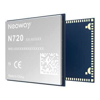
1.1 Overview N720 is an industrial-grade 4G module developed on Qualcomm platform. Its dimensions are 30 mm x 28 mm x 2.8 mm. This module has an ultra-wide operating temperature range of -40 ° C to +85 ° C and electrostatic capacity of 8 kV. -
Page 10: Block Diagram
UMTS: B1, B5 FDD-LTE: B1, B3, B7, B8, B28 Taiwan Cat4 UMTS: B1, B8 GSM/GPRS/EDGE: 900/1800 MHz FDD-LTE: B3, B5 India Cat4 TDD-LTE: B40 1.2 Block Diagram Figure 1-1 shows the block diagram of N720. Copyright © Neoway Technology Co., Ltd... -
Page 11: Features
PWRKEY Base Band RESET Digital Interface UART SDIO 1.3 Features Table 1-1 N720 baseband and wireless features Specifications Description Power supply VBAT: 3.3V to 4.3V; Typical value: 3.8 V Current in sleep mode < 4 mA Standby current < 20 mA Operating temperature -40 °... - Page 12 1 USB2.0 high-speed interface 2 15-bit ADC interfaces, detectable voltage ranging from 0.1 V to 1.7 V SDIO 1 SDIO interface, used for WLAN 1 PCM interface 1 I2C interface, supports host mode only Copyright © Neoway Technology Co., Ltd...
-
Page 13: Application Interfaces
Table 2-1 N720 dimensions Specifications N720 Dimensions (H x W x D) 28± 0.1 mm x 30± 0.1 mm x 2.8± 0.1 mm Weight 5.1 g Package 100-pin LGA Figure 2-1 N720 module pin definition (Top View) Copyright © Neoway Technology Co., Ltd... -
Page 14: Pin Description
N720 Hardware User Guide 2.2 Pin Description IO: input/output DO: Digital output PO: Power output AO: Analog output DI: Digital input PI: Power input AI: Analog input Table 2-2 N720 pin description Power Name Function Level Feature (V) Remarks Domain Power Supply VBAT... - Page 15 1.8 V UART2_RXD UART data receive min=1.35 V; max=2.1 V min=-0.3 V; max=0.45 V; Leave these pins unconnected if they are not 1.8 V UART2_CTS Clear to send used. min=1.35 V; max=2.1 V Copyright © Neoway Technology Co., Ltd...
- Page 16 = 1.2 V; max = 0.45 V; min = 1.35 V UIM_DATA UIM data 1.8 V/3 V 3V USIM: max = 0.8 V min = 1.95 V max = 0.45 V min = 2.6 V Copyright © Neoway Technology Co., Ltd...
- Page 17 The audio function is optional. It requires PCM_DOUT PCM data output 1.8V min=1.35V PCM, I2C, and I2S_MCLK signals. Leave these pins unconnected if they are not used. min=-0.3V; PCM_DIN PCM data input max=0.45V; 1.8V min=1.6V; Copyright © Neoway Technology Co., Ltd...
- Page 18 Leave this pin unconnected if it is not used. control transmit min=1.35V 1.8V power supply Used to connect to the crystalloid of the VDDXO_1P8 Vnorm=1.8V 1.8V output external WLAN chipset via a pull-up resistor. Copyright © Neoway Technology Co., Ltd...
- Page 19 = 1.4V max=0.45V WLAN mode control WAKE_ON_WIRELESS 1.8V Leave this pin unconnected if it is not used. signal min=1.35V WLAN_SLEEP_CLK 1.8V Leave this pin unconnected if it is not used. WIFI sleep clock Copyright © Neoway Technology Co., Ltd...
- Page 20 1.8 V Leave this pin unconnected if it is not used. indicator control min=1.35 V; Other Pins FORCE_USB_BOOT External GNSS LNA V min=-0.3V; 1.8 V Leave this pin unconnected if it is not used. Copyright © Neoway Technology Co., Ltd...
- Page 21 7, 8, 15, 16, 18, 19, 21, 22, 23, 24, Leave them unconnected. 25, 65, 66, 67, 68, 69, Do not use them. 70, 71, 72, 73, 78, 80, 84, 85, 86, 87, 90, 96 Copyright © Neoway Technology Co., Ltd...
-
Page 22: Power Control Interfaces
3.3 V. Figure 2-2 Current peaks and voltage drops Input current 3.8 V Voltage 3.3 V Keep the voltage above 3.3 V 3.7 ms 7.4 ms 10.7 ms 0 ms Copyright © Neoway Technology Co., Ltd... -
Page 23: Figure 2-3 Capacitors Used For The Power Supply
MIC29302WU in Figure 2-4 is an LDO and outputs a maximum current of 3 A to ensure the performance of the module. Figure 2-4 Reference design of power supply control PWR_EN VBAT VOUT MIC29302WU VCC_IN_5V 470uF 0.1 uF 100pF 33pF 10 uF 4.75K 100 uF 0.1 uF Copyright © Neoway Technology Co., Ltd... -
Page 24: Figure 2-5 Reference Design Of Power Supply Controlled By P-Mosfet
Power Supply Protection Add TVS diodes (VRWM=5 V) on the VBAT power supply, especially in automobile applications. For some stable power supplies, Zener diodes can decrease the power supply overshoot. SMF5.0AG from ONSEMI is an option. Copyright © Neoway Technology Co., Ltd... -
Page 25: Figure 2-6 Reference Designs Of Separated Power Supply
Never use a diode to make the drop voltage between a higher input and module power. Otherwise, Neoway will not provide warranty for product issues caused by this. In this situation, the diode will obviously decrease the module performances, or result in unexpected restarts, due to the forward voltage of diode will vary greatly in different temperature and current. -
Page 26: Vddio_1P8
PWRKEY USER_ON If the module is powered on but the power-on sequence has not been completed, the states of each pin are uncertain. The power-on sequence of the module is shown in Figure 2-9. Copyright © Neoway Technology Co., Ltd... -
Page 27: Figure 2-9 N720 Power-On/Off Sequence
N720 Hardware User Guide Figure 2-9 N720 power-on/off sequence VBAT t >200ms t >2s PWRKEY <0.6V RESET_N Active Inactive Inactive UART Active Inactive Inactive If application does not require power-on control, pull the PWRKEY pin down to GND through 1.5 kΩ... -
Page 28: Reset
Figure 2-12 Reset circuit with triode separating VDD_EXT 2V8/3V3/3V0 RESET In a circuit shown in Figure 2-12, VDD_EXT=2.8V/3.3V/3.0V, R1=4.7K, R2=47K. Figure 2-13 shows the reset sequence. Figure 2-13 N720 reset sequence VBAT RESET Active Inactive USB/UART Copyright © Neoway Technology Co., Ltd... -
Page 29: Usb Interface
Leave this pin unconnected if it is not used. USB can be used to download firmware for N720 and establish data communication for commissioning. If the module is used only as USB device, the recommended USB circuit to use is shown in Figure 2-14. -
Page 30: Uim Card Interface
A pull-up resistor is recommended N720 supports 1.8 V/3 V UIM cards. VUIM is the power supply pin of the UIM card and its maximum load is 30 mA. The UIM_DATA pin is not pulled up internally, so reserve a pull-up resistor externally in design. -
Page 31: Gpio Interfaces
The ESD protection diodes or small capacitors should be close to UIM card on the PCB. 2.6 GPIO Interfaces N720 supports UART, allowing GPIO configuration to meet requirements for connecting to different devices. For the open multi-function GPIO interface, please inquiry our technical support engineers. The level of the module interface is 1.8 V. -
Page 32: Uart
Support only host mode 2.6.1 UART N720 provides 1 UART interface, which support hardware flow control and 4 Mbps at most. The high level is 1.8V. Figure 2-17 shows the reference design of the UART interface. Figure 2-17 Reference design of the UART interface... -
Page 33: Figure 2-18 Recommended Level Shifting Circuit 1
TX and RX ports of the module. Voltage at VCC_IO is the voltage at the UART of the MCU while voltage at VDDIO_1V8 is the voltage at the UART of the module. Figure 2-19 shows another recommended level shifting circuit. Copyright © Neoway Technology Co., Ltd... -
Page 34: Adc
2.6.2 ADC N720 provides two ADC channels, and the detectable voltage ranges from 0.1 V to 1.7 V. ADC pin supports highest precision of 15 bit and it can be used for temperature and other check. If this pin is used to measure SIM card temperature on power terminals, refer to Neoway GPRS Module ADC User Guide. -
Page 35: Net_Light
10KΩ When the module is running, the LED indicator is driven by the NET_LIGHT pin to indicate different module status with its various blink behaviors. N720 supports multiple blink style and users can configure it using AT commands. 2.6.4 DTR Generally, the DTR pin is used to control sleep mode together with AT commands. -
Page 36: Ring Signal Indicator
RING pin outputs 30 ms low pulses in a period of 5 second. After the call is answered, the high level restores. Figure 2-21 RING indicator for incoming call SMS: Upon receipt of SMS, the module outputs one 35 ms low pulse. Figure 2-22 RING indicator for SMS 35 ms Copyright © Neoway Technology Co., Ltd... -
Page 37: Audio Interfaces
The PCM interface supports master and slave mode. Its reference high level is 1.8V. The following figure shows the PCM connection. Figure 2-23 PCM connection The PCM clock can be up to 2048 KHz. The following figures show the PCM timing. Figure 2-24 PCM synchronization timing t(sync) PCM_SYNC t(synca) t(syncd) Copyright © Neoway Technology Co., Ltd... -
Page 38: Figure 2-25 Pcm Data Input Timing
Set-up time from PCM_DIN high to t(sudin) PCM_CLK low Hold time from PCM_CLK low to t(hdin) PCM_DIN high Delay time from PCM_CLK high to t(pdout) PCM_DOUT low Delay time from PCM_CLK low to t(zdout) PCM_DOUT high impedance Copyright © Neoway Technology Co., Ltd... -
Page 39: I2C
SDIO data bit 3 Leave this pin unconnected if it is not used. The SDIO interface of the N720 module supports the SDIO 3.0 interface protocol and supports 1.8V. The following figure shows the SDIO connection. Copyright © Neoway Technology Co., Ltd... -
Page 40: Figure 2-27 Sdio Connection
DS, HS, SDR12, SDR25, SDR50, and SDR104. The following figures and table shows the sequences and parameters of SDR and DDR modes respectively. Figure 2-28 SDIO SDR timing SD_CLK t(csurd) t(chrd) t(dsurd) t(dhrd) Read t(pddwr) t(cdvrd) t(pdcwr) t(dvrd) Write Copyright © Neoway Technology Co., Ltd... -
Page 41: Wlan Control
Pin No. Function Remarks Multiplexing function FORCE_USB_BOOT WLAN/LTE co-exist LTE_COEX_RX_UART control receive Leave this pin unconnected if it is not used. WLAN/LTE co-exist Leave this pin unconnected if it LTE_COEX_TX_UART control transmit is not used. Copyright © Neoway Technology Co., Ltd... -
Page 42: Figure 2-30 32Khz Clock Signal Timing
WLAN chipset. The following figure and table shows the clock signal timing and parameters respectively. Figure 2-30 32KHz clock signal timing Table 2-6 Timing parameters of 32KHz clock signal Parameter Signal Min. Typical Unit Clock frequency 32.768 Copyright © Neoway Technology Co., Ltd... -
Page 43: Commissioning Interfaces
The module can enter the fast boot mode by connecting the FORCE_USB_BOOT pin to VDDIO_1P8V during the startup. This is the last method to troubleshoot the abnormality that the module cannot start or operation properly. Figure 2-31 Reference design of the fast boot interface Copyright © Neoway Technology Co., Ltd... -
Page 44: Rf Interface
3.1 2G/3G/4G RF Design and PCB Layout ANT_MAIN and ANT_AUX are the antenna pins of N720. A 50 Ω antenna is required. VSWR ranges from 1.1 to 1.5. The antenna should be well matched to achieve best performance. It should be installed far away from high-speed logic circuits, DC/DC power or any other strong disturbing sources. -
Page 45: Figure 3-2 Recommended Rf Pcb Design
RF antenna can also be connected to the module by soldering. In this manner, ensure proper soldering in case of damage that lowers RF performance. Figure 3-4 shows the pictures of these two connections. Figure 3-4 RF connections Copyright © Neoway Technology Co., Ltd... -
Page 46: Gnss Rf Design And Pcb Layout
PCB traces and the traces should be as short as possible. The power supply of the active antenna is fed by the 100 nH inductance through the signal traces. Copyright © Neoway Technology Co., Ltd... -
Page 47: Figure 3-6 Power Supply Reference For Active Antenna
RF signals. RCLAMP0521P from Semtech or ESD5V3U1U from Infineon is recommended. On the PCB, keep the RF signals and RF components away from high-speed circuits, power supplies, transformers, great inductors, the clock circuit of single-chip host, etc. Copyright © Neoway Technology Co., Ltd... -
Page 48: Electrical Features And Reliability
N720 Hardware User Guide 4 Electrical Features and Reliability 4.1 Electrical Features Table 4-1 N720 electric features Module Status Minimum Value Typical Value Maximum Value 3.3 V 3.8 V 4.3 V VBAT If the voltage is too low, the module might fail to start. If the voltage is too high or there is a voltage burst during the startup, the module might be damaged permanently. -
Page 49: Esd Features
Electronic products need to pass several ESD tests. The following table shows the ESD capability of key pins of our module. Add ESD protection to those pins in accordance to the application to ensure product quality when designing better products. Humidity: 45% Temperature: 25 ° C Table 4-3 N720 ESD features Testing Point Contact Discharge Air Discharge VBAT ±... -
Page 50: Rf Feature
N720 Hardware User Guide 5 RF Feature 5.1 Operating Band Table 5-1 N720 operating band Operating band Uplink Downlink GSM850 824~849 MHz 869~894 MHz EGSM900 880~915 MHz 925~960 MHz DCS1800 1710~1785 MHz 1805~1880 MHz PCS1900 1850~1910 MHz 1930~1990MHz CDMA BC0... -
Page 51: Tx Power And Rx Sensitivity
1880~1920 MHz TDD-LTE B40 2300~2400 MHz 2300~2400 MHz TDD-LTE B41 2555~2655 MHz 2555~2655 MHz 5.2 TX Power and RX Sensitivity Table 5-2 N720 RF power and RX sensitivity Band Transmitting Power Receiving Sensitivity GSM850 33 dBm+2/-2 dBm <-108 dBm EGSM900 33 dBm+2/-2 dBm <-108 dBm... -
Page 52: Gnss Features
Cold start (in air) <35s Update frequency 1Hz by default CNRin/CNRout 3 dB Max. positioning altitude 18000 m Max. positioning speed 515 m/s Max. positioning acceleration GNSS data type NMEA-0183 GNSS antenna type Passive/active antenna Copyright © Neoway Technology Co., Ltd... -
Page 53: Mechanical Feature
N720 Hardware User Guide 6 Mechanical Feature 6.1 Dimensions Figure 6-1 Dimensions of N720 Copyright © Neoway Technology Co., Ltd... -
Page 54: Pcb Foot Print
N720 Hardware User Guide 6.2 PCB Foot Print Figure 6-2 N720 PCB foot print (Top View) A test point is reserved at the Silk Area. It is recommended that a layer of white ink is added in case short circuit. Do not layout any trace under the JTAG pin. -
Page 55: Mounting And Packaging
Otherwise, the components inside the module might get misplaced. 7.2 Packaging N720 modules are packaged in sealed bags on delivery to guarantee a long shelf life. Package the modules again in case of opening for any reasons. If exposed to air for more than 48 hours at conditions not worse than 30 ° C/60% RH, a baking procedure should be done before SMT. -
Page 56: Smt Temperature Curve
When using only solder pastes with lead, please ensure that the reflow temperature is kept at 220 ° C for more than 45 seconds and the peak temperature reaches 240 ° C. Neoway will not provide warranty for heat-responsive element abnormalities caused by improper temperature control. Copyright © Neoway Technology Co., Ltd... -
Page 57: Abbreviations
Enhanced GSM Electro Static Discharge GPRS General Packet Radio Service Global Standard for Mobile Communications IMEI International Mobile Equipment Identity Light Emitting Diode Printed Circuit Board Radio Frequency Subscriber Identification Module UART Universal asynchronous receiver-transmitter Copyright © Neoway Technology Co., Ltd...
Need help?
Do you have a question about the N720 and is the answer not in the manual?
Questions and answers