Advertisement
Quick Links
325 Log Canoe Circle • Stevensville MD 21666 • www.videomount.com
Phone: 410.643.6390 • Fax: 410.643.6615
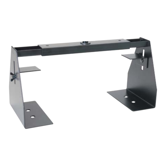
VH-001
WARNING: The installer of these products must verify that the mount surface, ceiling
or wall, will safely support the combined weight of all attached equipment and
hardware. Video Mount Products will not be held liable for the improper use or
installation of its products.
Advertisement

Related Manuals for VMP VH-001


Summary of Contents for VMP VH-001
- Page 1 325 Log Canoe Circle • Stevensville MD 21666 • www.videomount.com Phone: 410.643.6390 • Fax: 410.643.6615 VH-001 WARNING: The installer of these products must verify that the mount surface, ceiling or wall, will safely support the combined weight of all attached equipment and hardware.
- Page 2 VH-001 to. If you are trying to connect the VH-001 to a W-13 or a C-13 proceed to step 3. If you are trying to connect the VH-001 to a C-20, C-27, W-20, or W- 27 proceed to step 6. If you are trying to connect the VH-001 to a new style VMP014/024, VMP036/038, VMP042/044, or VMP046/048 proceed to step 9.
- Page 3 C20/C27) from the depressions in the platform. Next insert the M6 screw that is 80 mm long (#15 for the VH-001) through the top of the force arm (#5 for W20/W27/C20/C27) and place the spacer (#16 for the VH-001) around the screw underneath the force arm (#5 for W20/W27/C20/C27).
- Page 4 001) and force arm and then using the 3/8” screw (#24 for VH- 004) attach the force arm to the nut. Then use a brake screw (#23 for VH-001) to secure the 3/8” screw in the nut. Once this is completed please proceed to step 14.
- Page 5 ¼” – 20UNC screws (#5 and #4 for VH-001). Now take the Velcro (#6 for VH-001) and apply it to the equipment you are going to place in the VH-001 and on the extension holders (#2 for VH-001). You should apply the Velcro to the bottom left and right sides of your equipment along the edges.
Need help?
Do you have a question about the VH-001 and is the answer not in the manual?
Questions and answers