Table of Contents
Advertisement
Quick Links
Operator's Manual
POWER FEED
Register your machine:
www.lincolnelectric.com/register
Authorized Service and Distributor Locator:
www.lincolnelectric.com/locator
Save for future reference
Date Purchased
Code: (ex: 10859)
Serial: (ex: U1060512345)
IM10180
| Issue Date Jan- 14
© Lincoln Global, Inc. All Rights Reserved.
™
25M NNS
For use with machines having Code Numbers:
12244
Advertisement
Table of Contents

Related Manuals for Lincoln Electric POWER FEED 25M NNS


Summary of Contents for Lincoln Electric POWER FEED 25M NNS
- Page 1 Operator’s Manual ™ POWER FEED 25M NNS For use with machines having Code Numbers: 12244 Register your machine: www.lincolnelectric.com/register Authorized Service and Distributor Locator: www.lincolnelectric.com/locator Save for future reference Date Purchased Code: (ex: 10859) Serial: (ex: U1060512345) IM10180 | Issue Date Jan- 14 ©...
- Page 2 THANK YOU FOR SELECTING A QUALITY PRODUCT BY KEEP YOUR HEAD OUT OF THE FUMES. DON’T get too close to the arc. LINCOLN ELEC TRIC. Use corrective lenses if necessary to stay a reasonable distance away from the arc. READ and obey the Safety Data PLEASE EXAMINE CARTON AND EQUIPMENT FOR Sheet (SDS) and the warning label DAMAGE IMMEDIATELY...
- Page 3 W117.2-1974. A Free copy of “Arc Welding Safety” booklet E205 is available from the Lincoln Electric Company, 2.d. All welders should use the following procedures in order to 22801 St. Clair Avenue, Cleveland, Ohio 44117-1199.
-
Page 4: Electric Shock Can Kill
SAFETY ELECTRIC SHOCK ARC RAYS CAN BURN. CAN KILL. 3.a. The electrode and work (or ground) circuits are 4.a. Use a shield with the proper filter and cover plates to protect your electrically “hot” when the welder is on. Do eyes from sparks and the rays of the arc when welding or not touch these “hot”... - Page 5 SAFETY WELDING AND CUTTING CYLINDER MAY EXPLODE IF SPARKS CAN CAUSE DAMAGED. FIRE OR EXPLOSION. 7.a. Use only compressed gas cylinders containing the correct shielding gas for the process used 6.a. Remove fire hazards from the welding area. If and properly operating regulators designed for this is not possible, cover them to prevent the welding sparks the gas and pressure used.
- Page 6 Electromagnetic Compatibility (EMC) Product Standard for Arc Welding shielding the supply cable of permanently installed welding Equipment. It is for use with other Lincoln Electric equipment. It is equipment, in metallic conduit or equivalent. Shielding should be designed for industrial and professional use.
- Page 7 TABLE OF CONTENTS...
-
Page 8: Product Description
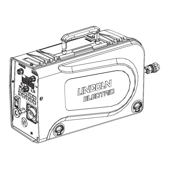
POWER FEED™ 25M NNS PRODUCT DESCRIPTION GENERAL DESCRIPTION General Physical Description The POWER FEED™ 25M NNS is a premium portable wire feeder for use with the Power Wave products. The wire feeder features a 2 roll MAXtrac™ drive coupled to a powerful motor for driving wire through difficult situations. -
Page 9: Input Voltage And Current
POWER FEED™ 25M NNS INSTALLATION TECHNICAL SPECIFICATIONS – POWER FEED™ 25M NNS K2536-6 INPUT VOLTAGE and CURRENT INPUT AMPERES INPUT VOLTAGE ± 10% 40 VDC RATED OUTPUT @ 104°F (40°C) DUTy CyCLE INPUT AMPERES 60% rating 500A GEARING - WIRE FEED SPEED RANGE-WIRE SIzE GMAW FCAW GEARING... - Page 10 POWER FEED™ 25M NNS INSTALLATION THUMB SCREW AND METAL TAB OF WELDING GUN ELECTRIC SHOCK can kill. WARNING • Turn the input power OFF at the disconnect switch or fuse box before attempting to connect or disconnect input power lines, output cables or control cables. •...
-
Page 11: Cable Connection
POWER FEED™ 25M NNS INSTALLATION CABLE CONNECTION WARNING There is one connector on the front of the POWER FEED™ 25M NNS for the gun trigger. (See 2-prong Figure A.2) ELECTRIC SHOCK CAN KILL. Figure A.2 • Turn the input power OFF at the welding power source before installation or chang- ing drive rolls and/or guides. - Page 12 POWER FEED™ 25M NNS INSTALLATION WELD CABLE SIZE To install: 1. Turn the input power off at the welding power source. 2. Connect one end of the center lead to the power source electrode Table A.1 located below are copper cable sizes recommended for different currents connection, and the other end to the wire feeder electrode connec- and duty cycles.
-
Page 13: Shielding Gas Connection
POWER FEED™ 25M NNS INSTALLATION SHIELDING GAS CONNECTION PROCEDURE TO INSTALL DRIVE ROLLS AND WIRE GUIDES WARNING WARNING CYLINDER may explode if damaged. ELECTRIC SHOCK can kill. •Keep cylinder upright and chained • Turn the input power OFF at the welding to support. -
Page 14: Remote Sense Lead Specifications
POWER FEED™ 25M NNS INSTALLATION REMOTE SENSE LEAD SPECIFICATIONS LOADING SPOOLS OF WIRE WARNING Welding with Multiple Arcs: ( See Figure A.6) • Keep hands, hair, clothing and tools away from rotating equipment. • Do not wear gloves when threading wire or Special care must be taken when more than one arc is welding simultaneously on a single part. -
Page 15: Typical System Configurations
POWER FEED™ 25M NNS INSTALLATION TYPICAL SYSTEM CONFIGURATIONS STANDARD FEATURES Arc Performance • STT™ capable when used with STT™ equipped Power Waves. • Waveform Control Technology™ for welds with good appear- ance and low spatter, even when welding nickel alloys. Wire Drive Patented 2 roll drive system. -
Page 16: Safety Precautions
OPERATION POWER FEED™ 25M NNS SAFETy PRECAUTIONS GRAPHIC SyMBOLS THAT APPEAR ON THIS MACHINE OR IN THIS MANUAL READ AND UNDERSTAND ENTIRE SECTION BEFORE OPERATING MACHINE. INPUT POWER WARNING • ELECTRIC SHOCK CAN KILL. Unless using COLD FEED fea- ture, when feeding with gun trig- ger, the electrode and drive mechanism are always electri- cally energized and could... -
Page 17: Definition Of Welding Terms
POWER FEED™ 25M NNS OPERATION DEFINITION OF WELDING TERMS DUTY CYCLE The POWER FEED™ 25M NNS is rated for 500 amps, 60% duty NON-SYNERGIC WELDING MODES cycle. The duty cycle is based on a 10 minute cycle. • A Non-synergic welding mode requires all welding process vari- For example, when welding at 500 amps, the POWER FEED™... -
Page 18: Recommended Processes
POWER FEED™ 25M NNS OPERATION RECOMMENDED PROCESSES • GMAW (CV, Synergic CV, Pulse, STT™, Power, Pulse on Pulse™) • FCAW • SMAW • GTAW (Lift Start only) • Solid wires .025" to 1/16" • Cored wires .035" to 5/64" EQUIPMENT LIMITATIONS ®... -
Page 19: Case Front Controls
POWER FEED™ 25M NNS OPERATION CASE FRONT CONTROLS 10. Gun Trigger Connection (SEE FIGURE B.1) 11. Right Display window 1. Left DISPLAy window Shows VOLTAGE or TRIM. Shows WIRE FEED SPEED or AMPERAGE. 12. Right Knob 2. Left KNOB Adjusts values in the right display. Adjusts values in left display. -
Page 20: On/Off Switch
If a special welding program not control the power to the welding power source. is desired, contact the local Lincoln Electric sales representative. All adjustments are made on the user interface. Because of the... - Page 21 POWER FEED™ 25M NNS OPERATION WIRE FEED SPEED / AMPS DISPLAY AND KNOB FIGURE B.2 The left display and knob are used to adjust either wire feed speed or amperage, depending upon the process selected. While welding, the amps LED lights when amperage is displayed and the wire feed speed LED lights when WFS is displayed.
- Page 22 POWER FEED™ 25M NNS OPERATION VOLTAGE / TRIM DISPLAY AND KNOB The right display and knob control voltage, trim or output depending upon the process selected. Once welding is complete, the display continues to show the welding voltage for 5 seconds. Process Display / Function Description...
- Page 23 POWER FEED™ 25M NNS OPERATION VOLTAGE / TRIM DISPLAY AND KNOB Process Display / Function Description Pulse welding controls the arc length with 'Trim' instead of volt- age. When trim (arc length) is adjusted, the Power Wave auto- matically recalculates the voltage, current and time of each part of the pulse waveform for the best result.
- Page 24 POWER FEED™ 25M NNS OPERATION SELECTING A WELD MODE Weld modes may be selected by mode number or through a search function. To select a weld mode: 1. Press the left button until the Weld Mode Menu LED illuminates. 2. Rotate the center knob to select the weld mode. To enter the search function: 1.
- Page 25 POWER FEED™ 25M NNS OPERATION WAVE CONTROL Wave Control is used to adjust the arc for exact preferences. The wave control functions vary for different processes and weld modes. Effect / Range Process Wave Control Description Name Arc Force adjusts the short circuit current for a soft arc, or for a forceful, driving arc.
- Page 26 POWER FEED™ 25M NNS OPERATION WAVE CONTROL Effect / Range Process Wave Control Description Name Peak Current acts similar to an arc pinch control. Peak Current sets the arc length and promotes good fusion. Higher peak current levels will cause the arc to broaden momentarily while increasing arc length.
- Page 27 POWER FEED™ 25M NNS OPERATION 2- STEP 4- STEP- TRIGGER OPERATION 2-Step Trigger The 2-Step - 4-Step switch changes the function of the gun trigger. 2-Step trigger operation switches the weld- ing output ON-OFF in direct response to the trigger. 4- Step trigger operation provides 'trigger interlock' capa- bility and gives the ability to control the amount of time spent in the arc start and arc crater steps.
- Page 28 POWER FEED™ 25M NNS OPERATION 2-Step Trigger 2-Step Trigger controls the welding sequence in direct response to the trigger. When the gun trigger is pulled, the welding system (power source and wire feeder) cycles through the arc starting sequence and into the main welding parameters. The welding system will continue to weld as long as the gun trigger is activated.
- Page 29 POWER FEED™ 25M NNS OPERATION 2-Step Trigger Example 2: 2-Step Trigger: Improved Arc Start and Arc End Tailoring the arc start and arc end is a common method for reducing spatter and improving weld quality. This can be accomplished with the Start and Burnback functions set to a desired values and Crater set to OFF. For this sequence, PREFLOW: Shielding gas begins to flow immediately when the gun trigger is pulled.
- Page 30 POWER FEED™ 25M NNS OPERATION 2-Step Trigger Example 3: 2-Step Trigger: Customized Arc Start, Crater and Arc End Aluminum is an example of where start, crater and burnback are commonly used to improve welding performance. For this sequence, PREFLOW: Shielding gas begins to flow immediately when the gun trigger is pulled. RUN-IN: After preflow time expires, the power source regulates to the start output and wire is advanced towards the work piece at the Run-In WFS.
- Page 31 POWER FEED™ 25M NNS OPERATION 4-Step Trigger 4-step trigger allows the operator to release the trigger once an arc has been established. To end the weld, the trigger is pulled and then released again. Two types of 4-Step Trigger are available. Use the set-up menu to select the desired type of operation. With current interlock, if the arc goes out for more than 0.5 seconds while the trigger is released, the welding process stops and goes to the idle state.
- Page 32 POWER FEED™ 25M NNS OPERATION 4-Step Trigger Example 2: 4-Step Trigger: Manual Control of Start and Crater times with Burnback ON. The 4-Step trigger sequence gives the most flexibility when the Start, Crater and Burnback functions are active. This is a popular choice when welding aluminum because extra heat may be needed during Start and less heat desired during crater.
- Page 33 POWER FEED™ 25M NNS OPERATION Spot Trigger The Spot Trigger may only be selected if the Spot Time has previously been set to a value other than 0.0 (OFF) and the Start and Crater are both OFF. Spot time causes the welding system to turn on for a fixed time, regardless if the trigger is held for a longer period of time. If the trig- ger is released before the spot timer is complete, welding stops.
- Page 34 POWER FEED™ 25M NNS OPERATION 4-Step Trigger: Special Considerations The response to the trigger with 4-step trigger active is dependent upon when the trigger is pulled/released and the settings for START and CRATER. Example 1. Pull the trigger to start feed of wire. When arc is established the sequencer will remain in START until the trigger is released. When the trigger is released, UPSLOPE begins.
-
Page 35: Start Options
POWER FEED™ 25M NNS OPERATION START OPTIONS The Start Options available depend upon the process and weld mode selected. Description Process Start Options Effect / Range SMAW (Stick) ---- ---- ---- Preflow 0 – 25.0 Time seconds Run-In sets the wire feed speed from the time the trigger is pulled until an arc is Auto, OFF, All GMAW (MIG) Run-In WFS... -
Page 36: Operation
POWER FEED™ 25M NNS OPERATION SETUP MENU FEATURES The Setup Menu gives access to the Setup Configuration. Stored in the setup configuration are user parameters that generally only need to be set at installation. The parameters are grouped as shown in the following table. PARAMETER DEFINITION P.1 through P.99... -
Page 37: User Defined Parameters
POWER FEED™ 25M NNS OPERATION USER DEFINED PARAMETERS Parameter Definition Exit Setup Menu This option is used to exit the setup menu. When P.0 is displayed, press the Left Button to exit the setup menu. Wire Feed Speed Units This option selects which units to use for displaying wire feed speed. English = inches/minute wire feed speed units (default). - Page 38 POWER FEED™ 25M NNS OPERATION USER DEFINED PARAMETERS Parameter Definition TIG Gas Control This option allows control over which gas solenoid actuates while TIG welding. "Valve (manual)" = No MIG solenoid will actuate while TIG welding, gas flow is manu- ally controlled by an external valve.
- Page 39 POWER FEED™ 25M NNS OPERATION USER DEFINED PARAMETERS Parameter Definition P.22 Arc Start/Loss Error Time This option can be used to optionally shut off output if an arc is not established, or is lost for a specified amount of time. Error 269 will be displayed if the machine times out. If the value is set to OFF, machine output will not be turned off if an arc is not established nor will output be turned off if an arc is lost.
- Page 40 POWER FEED™ 25M NNS OPERATION USER DEFINED PARAMETERS Parameter Definition P.82 Voltage Sense Display Allows viewing of Voltage Sense Lead Selection to aid in troubleshooting. The configuration is displayed as a text string on the lower display whenever the output is enabled. This parameter is not saved on a power cycle, but will be reset to False.
- Page 41 POWER FEED™ 25M NNS OPERATION USER DEFINED PARAMETERS Parameter Definition P.106 View Ethernet IP Address Used for viewing the IP address of Ethernet compatible equipment. Press the Right Button to read the IP Address. Press the Left Button to back out and exit this option. The IP address can- not be changed using this option.
- Page 42 POWER FEED™ 25M NNS OPERATION USER DEFINED PARAMETERS Parameter Definition P.504 Mode Select Panel Lock Selects between several Mode Select Panel lockout preferences. When a Mode Select Panel selection is locked and an attempt is made to change that parameter, a message will be dis- played on the lower display indicating the parameter is locked.
-
Page 43: User Memories
POWER FEED™ 25M NNS OPERATION DUAL PROCEDURE/MEMORy PANEL USER MEMORIES OPERATION Recall a memory with memory buttons To recall a user a memory, press one of the six user The Dual Procedure/Memory Panel performs three memory buttons. The memory is recalled when the functions: button is released. - Page 44 POWER FEED™ 25M NNS OPERATION LIMITS Set Limits: Press 5 Limits allow the welder to adjust the welding proce- seconds dure only within a defined range. GUN B Each user memory may have a different set of limits. For example, memory 1 may limit the WFS to 200 through 300 in/min, and memory 2 may limit the WFS to 275 through 310 in/min, while memory 3 may have no WFS limits.
- Page 45 POWER FEED™ 25M NNS OPERATION If the passcode does not equal zero (0000), enter the The memory value must always be less than or equal passcode now. If the passcode has been forgotten, a to the high limit, and greater than or equal to the low limit.
-
Page 46: Internal Controls
POWER FEED™ 25M NNS OPERATION INTERNAL CONTROLS ITEM DESCRIPTION Cold Feed / Gas Purge Switch Wire Drive Pressure Arm Internal Light Switch Internal Heater Switch Spindle Brake Gun Adapter Thumb Screw for securing the Gun Adapter B 31... -
Page 47: Cold Feed/Gas Purge Switch
POWER FEED™ 25M NNS OPERATION COLD FEED/GAS PURGE SWITCH PRESSURE ARM ADJUSTMENT HEATER ROCKER SWITCH ELECTRIC SHOCK can kill. Cold Feed and Gas Purge are com- LIGHT COLD FEED/GAS PURGE ROCKER SWITCH ROCKER SWITCH • Turn the input power OFF at the weld- bined into a Rocker switch. -
Page 48: Rear Controls
POWER FEED™ 25M NNS OPERATION REAR CONTROLS: ITEM DESCRIPTION Shielding Gas Inlet ArcLink Cable Connector Electrode Cable B 33... - Page 49 POWER FEED™ 25M NNS ACCESSORIES DRIVE ROLL KITS USED drive roll Kits, steel wires KP1505-030S .023-.030 (0.6-0.8mm) KP1505-035S .035 (0.9mm) KP1505-045S .045 (1.2mm) Includes: 4 Smooth V groove drive KP1505-052S .052 (1.4mm) rolls and inner wire guide. KP1505-1/16S 1/16 (1.6mm) KP1505-1 .035,.045 (0.9, 1.2mm) KP1505-2...
-
Page 50: Routine Maintenance
POWER FEED™ 25M NNS ACCESSORIES SAFETy PRECAUTIONS To verify the voltage display: • Set the welding power source and POWER FEED™ WARNING 25M NNS to a CV procedure that gives steady "spray" transfer in the arc. ELECTRIC SHOCK can kill. •... -
Page 51: Troubleshooting
HOW TO USE TROUBLESHOOTING GUIDE WARNING Service and Repair should only be performed by Lincoln Electric Factory Trained Personnel. Unauthorized repairs performed on this equipment may result in danger to the technician and machine operator and will invalidate your factory warranty. For your safety and to avoid Electrical Shock, please observe all safety notes and precautions detailed throughout this manual. - Page 52 POWER FEED™ 25M NNS TROUBLE SHOOTING Observe all Safety Guidelines detailed throughout this manual PROBLEMS POSSIBLE RECOMMENDED (SyMPTOMS) CAUSE COURSE OF ACTION Linc-Net System Error Codes Fault Code Description Possible Adjustments 1. Verify the power source is operat- Err 006 1.
- Page 53 4. The electrode is rusty or dirty. 4. Use only clean electrode. Use quality electrode, like L-50 or L-56 from Lincoln Electric. 5. The contact tip is partially melted 5. Replace the contact tip. or has spatter.
- Page 54 POWER FEED™ 25M NNS TROUBLE SHOOTING Observe all Safety Guidelines detailed throughout this manual PROBLEMS POSSIBLE RECOMMENDED (SyMPTOMS) CAUSE COURSE OF ACTION Output Problems Variable or "hunting" arc. 1. Wrong size, worn and/or melted 1. Replace the contact tip. contact tip. 2.
- Page 55 POWER FEED™ 25M NNS DIAGRAMS...
- Page 56 POWER FEED™ 25M NNS DIAGRAMS...
- Page 57 WARNING Do not touch electrically live parts or Keep flammable materials away. Wear eye, ear and body protection. electrode with skin or wet clothing. Insulate yourself from work and AVISO DE ground. Spanish PRECAuCION No toque las partes o los electrodos Mantenga el material combustible Protéjase los ojos, los oídos y el bajo carga con la piel o ropa moja-...
- Page 58 WARNING Keep your head out of fumes. Turn power off before servicing. Do not operate with panel open or Use ventilation or exhaust to guards off. remove fumes from breathing zone. AVISO DE Spanish PRECAuCION Los humos fuera de la zona de res- Desconectar el cable de ali- No operar con panel abierto o piración.
- Page 59 Lincoln Electric for advice or information about their use of our products. We respond to our customers based on the best information in our possession at that time. Lincoln Electric is not in a position to warrant or guarantee such advice, and assumes no liability, with respect to such information or advice.
Need help?
Do you have a question about the POWER FEED 25M NNS and is the answer not in the manual?
Questions and answers