Table of Contents
Advertisement
Quick Links
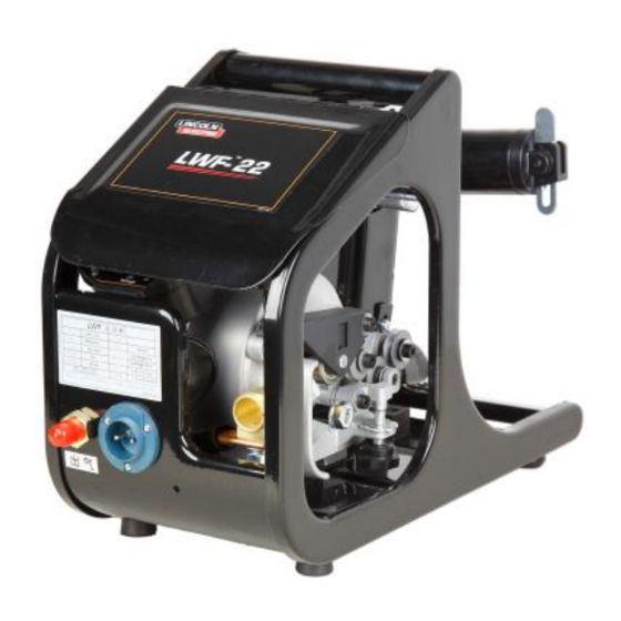
LWF -22 & LWF -24 PLUS Wire Feeder
Product Number
Date of Purchase:
Serial Number:
Code Number:
Model:
Where Purchased:
LWF-22
LWF-24 PLUS
OPERATOR'S MANUAL
Shanghai Lincoln Electric Company
No195, Lane 5008, HuTai Road Shanghai 201907
Tel: (021) 6673 4530
K60084-2 / 76202
K60086-2 / 76204
Safety Depends on You
Lincoln arc welding and cutting equipment is
designed and built with safety in mind. However,
your overall safety can be increased by proper
installation and thoughtful operation on your
part. DO
NOT INSTALL, OPERATE OR
REPAIR
THIS
EQUIPMENT
READING THIS MANUAL AND THE SAFETY
PRECAUTIONS CONTAINED THROUGHOUT.
And, most importantly, think before you act and
be careful.
Fax: (021) 6602 6621
IM7105-1
October, 2015
Export Rev. 02
WITHOUT
Advertisement
Table of Contents

Related Manuals for Lincoln Electric LWF-22


Summary of Contents for Lincoln Electric LWF-22
- Page 1 READING THIS MANUAL AND THE SAFETY PRECAUTIONS CONTAINED THROUGHOUT. And, most importantly, think before you act and be careful. OPERATOR’S MANUAL Shanghai Lincoln Electric Company No195, Lane 5008, HuTai Road Shanghai 201907 Tel: (021) 6673 4530 Fax: (021) 6602 6621...
- Page 2 That you purchase a copy of “ Safety in Welding & Cutting – ANSI Standard Z49.1 ” from the American Welding Society, P.O. Box 351040, Miami, Florida 33135 or CSA Standard W117.2-1974. A Free copy of “Arc Welding Safety ” booklet E205 is available from the Lincoln Electric Company, 22801 St. Clair Avenue, Cleveland, Ohio 44117-1199.
- Page 3 SAFETY ELECTRIC SHOCK can ARC RAYS can burn. Kill. 3.a. Use a shield with the proper filter and cover plates to protect your eyes from sparks and the rays of the arc welding or observing open arc welding. 2.a. The electrode and work ( or ground) The headshield and filter lens should conform to ANSI circuits are electrically “hot”...
- Page 4 SAFETY WELDING SPARKS can CYLINDER may cause fire or explosion. explode if damaged. 6.a. Use only compressed gas cylinders containing the 5.a. Remove fire hazards from the welding area. If this is not correct shielding gas for the process used and possible, cover them to prevent the welding sparks from properly operating regulators designed for the gas starting a fire.
- Page 5 SAFETY Please Examine Carton and Equipment For Damage Immediately When this equipment is shipped, title passes to the purchaser upon receipt by the carrier. Consequently, Claims for material damaged in shipment must be made by the purchaser against the transportation company at the time the shipment is received. Please record your equipment identification information below for future reference.
-
Page 6: Table Of Contents
CONTENTS TABLE OF CONTENTS Installation Section A Technical Specification Safety Precautions Installation Instructions Welding Cable Gas Hose Control Cable Option Extension Cables Welding Gun Connection Diagram: LWF Feeder to Lincoln OPTIMARC Operation Section B Installing Drive Rolls Loading the Wire Spool -24 PLUS Maintenance Section C... -
Page 7: Installation
INSTALLATION TECHNICAL SPECIFICATIONS – LWF Wire Feeders MODEL -22, LWF -24 PLUS INPUT POWER Supplied by power source RECOMMENDED WIRE SIZES 0.8mm, 1.0mm, 1.2mm, 1.4mm, 1.6mm,2.0mm WIRE FEED SPEED 1.5 to 18m/min WELDING WIRE SPOOL (Max. load 20 kg) SHAFT DIAMETER OUTSIDE DIAMETER WIDTH 50mm... -
Page 8: Installation Instructions
INSTALLATION INSTALLATION INSTRUCTION WELDING CABLE The needed cable assembly for the LWF feeders includes a control cable, welding cable and gas hose. The lengths are made based on to the specific requirements from end users. The feeder has a stud being used to connect the welding cable. For self-shielded wire, the welding cable should be bolted to either the “+”... -
Page 9: Operation
OPERATION INSTALLING DRIVE ROLLS LWF™-22: One reversible drive roll needs to be installed on each LWF -22 wire feeder. Normally each drive roll has two different size grooves for feeding different diameter wire. One groove is for feeding 0.8/1.0/1.2mm and the other groove is for feeding 1.0/1.2/1.6mm. Ensure that the drive roll is installed using the correct groove for the wire diameter being used. -
Page 10: Lwf Tm -24 Plus
OPERATION LWF™-24 PLUS: Loosen the retainer on the spindle and put on the welding wire spool. Next, replace the retainer and tighten the screw. Release the pressure handle and lift the pressure arm, insert the welding wire into conduit and V groove of feed roll, then insert it into the feedplate. Then insert the welding wire into V groove of another feed roll and contact tip. -
Page 11: Maintenance
MAINTENANCE Note: Motor and gear box are maintenance free products, do not open them for maintaining, repairing or oiling. Contact your nearest Lincoln Electric Service Center if a fault occurs. Location Inspection Points Note Check if there is any dust and... -
Page 12: Schematic Diagram Section D
SCHEMATIC DIAGRAM... - Page 13 Except for special instructions, experiments on welding machines are conducted in accordance with the general standard of IEC60974-1; experiments on welding consumables are conducted in accordance with the general standard of AWS; for speci c applicable standards on welding consumables please refer to the product page. The product performance data of this website and related attachments are from LINCOLN ELECTRIC American application engineering laboratory.
Need help?
Do you have a question about the LWF-22 and is the answer not in the manual?
Questions and answers