Moxa Technologies OnCell Series Quick Installation Manual
Hide thumbs
Also See for OnCell Series:
- Quick installation manual (15 pages) ,
- Quick installation manual (17 pages) ,
- Quick installation manual (15 pages)
Table of Contents
Advertisement
Quick Links
Quick Installation Guide
Moxa Americas:
Toll-free: 1-888-669-2872
Tel:
1-714-528-6777
Fax:
1-714-528-6778
Moxa Europe:
Tel:
+49-89-3 70 03 99-0
Fax:
+49-89-3 70 03 99-99
Moxa India:
Tel:
+91-80-4172-9088
Fax:
+91-80-4132-1045
OnCell 3120-LTE-1
Moxa OnCell Series
Version 1.0, October 2019
Technical Support Contact Information
www.moxa.com/support
2019 Moxa Inc. All rights reserved.
Moxa China (Shanghai office):
Toll-free: 800-820-5036
Tel:
+86-21-5258-9955
Fax:
+86-21-5258-5505
Moxa Asia-Pacific:
Tel:
+886-2-8919-1230
Fax:
+886-2-8919-1231
P/N: 1802031200010
*1802031200010*
Advertisement
Table of Contents

Related Manuals for Moxa Technologies OnCell Series


Summary of Contents for Moxa Technologies OnCell Series
- Page 1 OnCell 3120-LTE-1 Quick Installation Guide Moxa OnCell Series Version 1.0, October 2019 Technical Support Contact Information www.moxa.com/support Moxa Americas: Moxa China (Shanghai office): Toll-free: 1-888-669-2872 Toll-free: 800-820-5036 Tel: 1-714-528-6777 Tel: +86-21-5258-9955 Fax: 1-714-528-6778 Fax: +86-21-5258-5505 Moxa Europe: Moxa Asia-Pacific: Tel:...
-
Page 2: Package Checklist
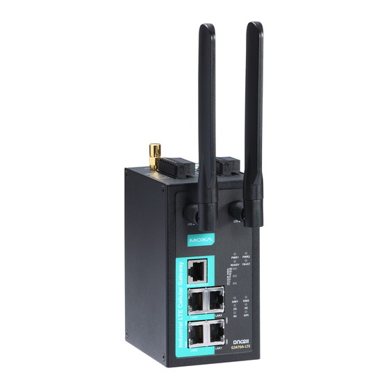
Overview The OnCell 3120-LTE-1 is a reliable, secure, LTE gateway with a state- of-the-art global LTE module. This 4G cellular gateway provides a more reliable connection to your Ethernet network for cellular applications. The OnCell 3120-LTE-1 is ideal for remote-access applications where power consumption needs to be well managed. - Page 3 Step 1: Insert a SIM card and turn on the OnCell 3120-LTE-1 1. Use a screwdriver to loosen the screws and remove the SIM card cover located on the top panel of the OnCell 3120-LTE-1. 2. Insert one or two 4G SIM cards (nano SIM) into the SIM card slot(s).
- Page 4 Panel Layout of the OnCell 3120-LTE-1 1. SIM card holders (SIM1/SIM2) 2. 2x2 MIMO cellular antenna port 3. 10/100 Base-T(X) Ethernet port 1 (RJ45) 4. 10/100 Base-T(X) Ethernet port 2 (RJ45) 5. USB port 6. DB9 serial port 7. LED display 8.
-
Page 5: Device Dimensions
Device Dimensions DIN-rail Mounting The OnCell 3120-LTE-1 Series comes with a DIN-rail kit attached to the back panel. Mount the OnCell 3120-LTE-1 Series on corrosion-free mounting rails that meet the EN 60715 standard. Installation STEP 1: Insert the upper lip of the DIN rail into the top hook of the DIN-rail mounting kit. -
Page 6: Wall Mounting (Optional)
To remove the OnCell 3120-LTE-1 from the DIN rail, pull down the lever at the bottom of the DIN-rail kit. Wall Mounting (optional) For some applications, it may be more convenient to mount the OnCell 3120-LTE-1 to a wall, as illustrated below: STEP 1: Remove the aluminum DIN-rail attachment plate... -
Page 7: Wiring Requirements
WARNING • This equipment is intended to be used in a Restricted Access Location, such as a dedicated computer room, where access can only be gained by SERVICE PERSONS or by USERS who have been instructed about the fact that the metal chassis of the equipment is extremely hot and may cause burns. -
Page 8: Sim Card Socket
Grounding the Moxa OnCell 3120-LTE-1 Grounding and wire routing help limit the effects of noise due to electromagnetic interference (EMI). Run the ground connection from the ground screw to the grounding surface prior to connecting devices. The minimum cross-sectional area of the grounding conductor should be equal to that of the input cable. -
Page 9: Communication Connections
Wiring the Power Input Top and front views of the terminal block connector are shown below: STEP 1: Insert the negative/positive DC wires into the V-/V+ terminals, and the ground wire into the GND terminal. STEP 2: To keep the DC wires from pulling loose, use a small flat-blade screwdriver to tighten the wire-clamp screws on the front of the terminal block connector. -
Page 10: Led Indicators
RS-232 RS-422/485-4w RS-485-2w TxD-(A) – DB9 Male Connector TxD+(B) – RxD+(B) Data+(B) RxD-(A) Data-(A) – – – – – – – – – Console Port The console port is an RS-232 port that you can connect to with a 4-pin pin header cable (in the package). -
Page 11: Specifications
Color Behavior Function (4 LEDs) Off Not active. Serial Green Transmitting or receiving data. (2 LEDs) Not active. Green LTE is connected. (1 LED) Green Blinking at 0.5-sec UMTS/HSPA/GSM/GPRS/EDGE is intervals connected. No cellular connection. Signal (3 Green Signal Cellular RSSI Range Comment LEDs) - Page 12 ATTENTION This device complies with part 15 of the FCC Rules. Operation is subject to the following two conditions: 1. This device may not cause harmful interference. 2. This device must accept any interference received, including interference that may cause undesired operation.
-
Page 13: Grounding-Wire Size
ATEX / IECEx Zone 2 Certification Information 1. ATEX Certificate Number: DEMKO 18 ATEX 2120X IECEx Certificate Number: IECEx UL 18.0113X 2. Ambient Range:-30°C ≤ Ta ≤ +70°C, or -30°C ≤ Tamb ≤ +70°C Rated Cable Temp ≧ 90 °C 3.
Need help?
Do you have a question about the OnCell Series and is the answer not in the manual?
Questions and answers