Table of Contents

Related Manuals for Moxa Technologies OnCell G3150A-LTE-EU-T


Summary of Contents for Moxa Technologies OnCell G3150A-LTE-EU-T
- Page 1 OnCell G3150A-LTE Series Quick Installation Guide Moxa OnCell Series Version 2.1, January 2021 Technical Support Contact Information www.moxa.com/support 2021 Moxa Inc. All rights reserved. P/N: 1802031500023 *1802031500023*...
-
Page 2: Package Checklist
Overview The OnCell G3150A-LTE is a reliable, secure, LTE gateway with state-of-the-art global LTE module. This 4G cellular gateway provides a more reliable connection to your Ethernet network for cellular applications. To enhance industrial reliability, the OnCell G3150A-LTE features isolated power inputs, which together with high-level EMS and wide-temperature support give the OnCell G3150A-LTE the highest level of device stability for any rugged environment. - Page 3 Step 2: Connect the OnCell G3150A-LTE to a notebook or PC Since the OnCell G3150A-LTE supports MDI/MDI-X auto-sensing, you can use either a straight-through cable or crossover cable to connect the OnCell G3150A-LTE to a computer. See the 10/100BaseT(X) Ethernet Port Connection section below for detailed instructions.
-
Page 4: Panel Layout Of The Oncell G3150A-Lte
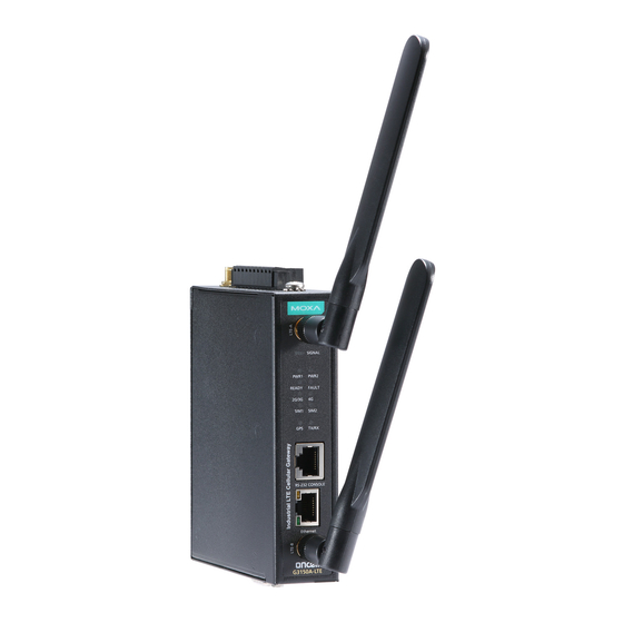
Panel Layout of the OnCell G3150A-LTE 1. GPS antenna connector (female SMA) 2. Terminal block (top-down PWR1 and PWR2, 1 digital relay and 2 digital inputs) 3. Grounding screw (M5) 4. 2x2 MIMO antenna ports for LTE (female SMA) 5. -
Page 5: Device Dimensions
Device Dimensions DIN-Rail Mounting DIN-Rail Kit Dimensions Unit = mm (inch) The OnCell G3150A-LTE Series computers come with a DIN-rail kit attached to the back panel. Mount the OnCell G3150A-LTE Series on corrosion-free mounting rails that meet the EN 60715 standard. - 5 -... -
Page 6: Installation
Installation STEP 1: Insert the upper lip of the DIN rail into the top hook of the DIN-rail mounting kit. STEP 2: Press the OnCell G3150A-LTE Series towards the DIN rail until it snaps into place. To remove the OnCell G3150A-LTE from the DIN rail, reverse steps 1 and 2 above. -
Page 7: Wiring Requirements
STEP 2: Mounting the OnCell G3150A-LTE to a wall requires 4 screws. Use the OnCell G3150A-LTE device, with wall mount plates attached as a guide, to mark the correct locations of the 4 screws. The heads of the screws should be less than 6.0 mm in diameter, and the shafts should be less than 3.5 mm in diameter, as shown in the figure at the right. -
Page 8: Grounding The Moxa Oncell G3150A-Lte
Read and Follow These Guidelines • Use separate paths to route wiring for power and devices. If power wiring and device wiring paths must cross, make sure the wires are perpendicular at the intersection point. NOTE Do not run signal or communications wiring and power wiring in the same wire conduit. -
Page 9: Connecting The Power Input
Connecting the Power Input Pinouts for the Power Inputs and Relay Output Name Usage DC Power Input 1 DC Power Input 2 Relay Output Digital Input COM_1 Digital Input GND Digital Input COM_2 Digital Input GND Wiring the Redundant Power Inputs The top two pairs of contacts of the 10-contact terminal block connector located on the top panel of the OnCell G3150A-LTE are used as the two DC inputs. -
Page 10: Communication Connections
Wiring the Digital Inputs The OnCell G3150A-LTE has two sets of digital inputs—DI1 and DI2. Each DI comprises of two contacts on the 6-pin terminal block connector located on the top panel of the OnCell G3150A-LTE. Refer to the Specifications section for detailed information on isolated digital input definition. -
Page 11: Led Indicators
Console Pinouts for 10-pin or 8-pin RJ45 10-Pin Description 8-Pin – – – NOTE The pin numbers for both 8-pin and 10-pin RJ45 connectors (and ports) are typically not labeled on the connector (or port). Refer to the pinout diagram above for details. LED Indicators The front panel of the Moxa OnCell G3150A-LTE contains several LED indicators. -
Page 12: Specifications
Type Color State Description Power is off or no error condition exists. 2G / 3G Amber Blinking GSM/GPRS/EDGE is connected. (slow at 500-ms intervals) UMTS/HSPA is connected. GSM/GPRS/EDGE/UMTS/HSPA is disconnected. Amber On LTE is connected LTE is disconnected. SIM1 Amber On/Off SIM 1 is active or inactive Blinking SIM 1 is not inserted or PIN code is incorrect... - Page 13 Serial Console Port 1, RS-232 (RJ45-type) Serial Port 1, RS-232, RS-485-4W , RS-485-2W, RS-422 (DB9 male) Serial Data Bits: 5,6,7,8 Communication Stop Bits: 1,1.5, 2 (when parity = None) Parameters Parity: None, Even, Odd, Space, Mark Baudrate: 75 bps to 921.6 kbps LED Indicators PWR1, PWR2, READY, FAULT, CELLULAR SIGNAL, SIM1, SIM2, 2G/3G, 4G, GPS, TX/RX...
- Page 14 Power Consumption 9.6 W (12 V/0.78 A to 48 V/0.2 A) Reverse Polarity Present Protection Standards and Certifications Safety OnCell G3150A-LTE-US: UL 60950-1 OnCell G3150A-LTE-US: FCC Part 15 Subpart B OnCell G3150A-LTE-EU: EN 61000-6-2/-4 Radio OnCell G3150A-LTE-US: FCC ID N7NMC7355 OnCell G3150A-LTE-EU: EN 301 489-1, EN 301 489-7, EN 301 511/4 Reliability...
-
Page 15: Atex Zone 2 Certification Information
ATTENTION Do not locate the antenna near overhead power lines or other electric light or power circuits, or where it can come into contact with such circuits. When installing the antenna, take extreme care not to come into contact with such circuits, because they may cause serious injury or death when there is a surge. -
Page 16: Grounding-Wire Size
Grounding-Wire Size The minimum cross-sectional area of the grounding conductor should be equal to that of the input cable. Moxa Inc. No. 1111, Heping Rd., Bade Dist., Taoyuan City 334004, Taiwan - 16 -...
Need help?
Do you have a question about the OnCell G3150A-LTE-EU-T and is the answer not in the manual?
Questions and answers