Table of Contents
Advertisement
Quick Links
- 1 Instruction Sheet
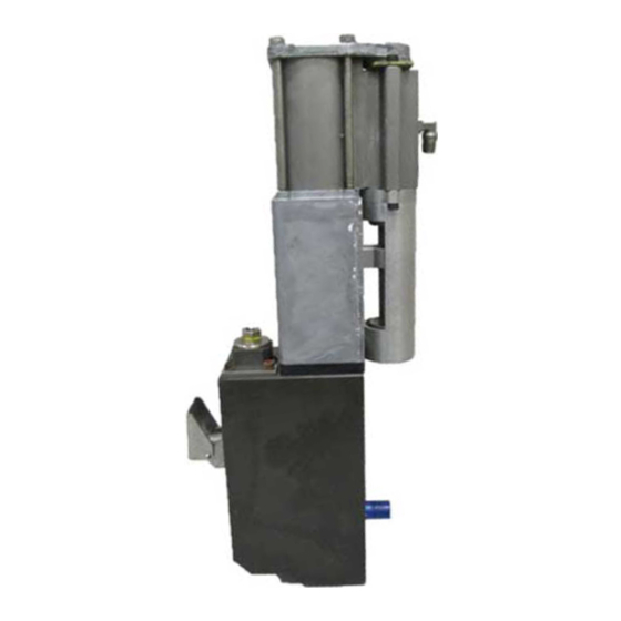
- 2 Remove the Pump
- 3 Install the New Pump
- 4 Pneumatic Panel Assembly Service Kit - P/N 1028307
- 5 Pressure Discharge Valve Service Kit - P/N 1028308
- 6 Manifold Service Kit - P/N 1028309
- 7 Rtd Service Kit - P/N 1028320
- 8 Hose/Gun Module Service Kit - P/N 1028328
- Download this manual
Advertisement
Table of Contents

Related Manuals for Nordson ProBlue 1028303


Summary of Contents for Nordson ProBlue 1028303
- Page 1 ProBlue Adhesive Melters Instruction Sheets Issued 10/02 Copyright Notice...
- Page 2 Instruction Sheet P/N 1029711A Pump Service Kit - P/N 1028303 Use this service kit to replace the pump assembly in any ProBluet WARNING: Risk of personal injury or equipment damage! Refer to Required Tools: adhesive melter. This kit contains two new O-rings that should be used to the safety information provided in the melter manual before servicing replace the existing O-rings that are located between the pump and the the melter.
- Page 3 Install the New Pump CAUTION: When reinstalling the pump, ensure that the RTD is fully seated in its slot and that the RTD wires are not caught between the pump and the manifold. Thread the 6-mm tube elbow into the air inlet port Reinstall the pump by reversing the sequence on the back of the new pump.
- Page 4 Instruction Sheet P/N 1029713A Pneumatic Panel Assembly Service Kit - P/N 1028307 Use this service kit to replace the pneumatic panel assembly on any WARNING: Risk of personal injury or equipment damage! Refer to Required Tools: ProBluet adhesive melter. the safety information provided in the melter manual before servicing the melter.
- Page 5 Instruction Sheet P/N 1029714A Pressure Discharge Valve Service Kit - P/N 1028308 Use this service kit to replace the pressure discharge valve in any WARNING: Risk of personal injury or equipment damage! Refer to Tools: ProBluet adhesive melter. the safety information provided in the melter manual before servicing 4-mm hex wrench the melter.
- Page 6 Instruction Sheet P/N 1029715A Manifold Service Kit - P/N 1028309 Use this service kit to replace the manifold O-rings on any ProBluet WARNING: Risk of personal injury or equipment damage! Refer to Required Tools: adhesive melter. the safety information provided in the melter manual before servicing the melter.
- Page 7 Remove the Pump Remove the pump as follows: a. Rotate the isolation valve handle upward b. Remove the three pump-mounting bolts. c. While pulling the pump away from the d. Lift the pump clear of the melter. until it is vertical. manifold, tilt the top of the pump toward the front of the melter and then remove the air line from the back of the pump.
- Page 8 Remove the Manifold Remove the two M5 screws and lock Disconnect the air line from washers, and then remove the backup the pressure discharge valve. and insulator plates. CAUTION: Use two wrenches, one on each terminal nut, when disconnecting the heater terminals.
- Page 9 Replace the Manifold O-Rings See the illustration to the right. P/N 1019515 Disassemble the isolation valve. P/N 941161 Remove and discard the seven existing O-rings. P/N 942080 P/N 942111 Lubricate each of the seven new O-rings with Parker Lubricant, and then install each O-ring into the manifold. Re-assemble the manifold.
- Page 10 Instruction Sheet P/N 1029719A ProBlue 10 Main Circuit Board Service Kit - P/N 1028323 Use this service kit to replace the main circuit board assembly in a model WARNING: Risk of personal injury or equipment damage! Refer to Tools: P10 ProBlue adhesive melter. the safety information provided in the melter manual before servicing Philips-head screwdriver the melter.
- Page 11 CAUTION: Before removing the new circuit board from its anti-static bag, ground yourself by touching any bare-metal part of the chassis or another grounded structure. Failure to properly ground yourself can cause electrostatic discharge resulting in damage to the board. Slide the main circuit board assembly Slide the new circuit board assembly into out of the electrical enclosure.
- Page 12 Instruction Sheet P/N 1029720A 6-Hose Extension Board Kit - P/N 1028324 Use this service kit to expand the hose capacity of any model P10 ProBlue WARNING: Risk of personal injury or equipment damage! Refer to Tools: adhesive melter from four hoses to six hoses. the safety information provided in the melter manual before servicing Philips-head screwdriver the melter.
- Page 13 CAUTION: Before removing the new circuit board from its anti-static bag, ground yourself by touching any bare-metal part of the chassis or another grounded structure. Failure to properly ground yourself can cause electrostatic discharge resulting in damage to the board. Slide the main circuit board assembly Connect the ribbon cable between the out of the electrical enclosure.
- Page 14 Instruction Sheet P/N 1029721A CPU Board Service Kit - P/N 1028325 Use this service kit to replace the CPU (central processor unit) on any WARNING: Risk of personal injury or equipment damage! Refer to Required Tools: ProBluet adhesive melter. the safety information provided in the melter manual before servicing the melter.
- Page 15 Instruction Sheet P/N 1029722A Operator’s Panel/Enclosure Service Kit - P/N 1028326 Use this service kit to replace the operator’s panel on a model P4 or P7 WARNING: Risk of personal injury or equipment damage! Refer to Required Tools: ProBluet adhesive melter. the safety information provided in the melter manual before servicing 6-mm open-end wrench the melter.
- Page 16 Detach the electrical enclosure door by removing the four M5 screws and matching washers. Detach the operator’s panel from both hinges by removing the four locknuts. Assemble the new operator’s panel to the hinges, and then re-attach the electrical enclosure door.
- Page 17 Instruction Sheet P/N 1029723A Operator’s Panel/Enclosure Service Kit - P/N 1028327 Use this service kit to replace the operator’s panel on a model P10 WARNING: Risk of personal injury or equipment damage! Refer to Required Tools: ProBluet adhesive melter. the safety information provided in the melter manual before servicing 6-mm open-end wrench the melter.
- Page 18 Detach the electrical enclosure door by removing the four M5 screws and matching washers. Detach the operator’s panel from both hinges by removing the four locknuts. Assemble the new operator’s panel to the hinges, and then re-attach the electrical enclosure door.
- Page 19 Instruction Sheet P/N 1029716A RTD Service Kit - P/N 1028320 Use this service kit to replace either the tank or the manifold RTD. The kit WARNING: Risk of personal injury or equipment damage! Refer to Tools: contains a ceramic terminal block that must be installed the first time you the safety information provided in the melter manual before servicing Wire cutters replace either RTD.
- Page 20 Replacing the Manifold RTD Switch the melter off. Relieve system hydraulic pressure. Refer to the To replace the manifold RTD you must first remove the pump. If the temperature of the tank is below 120 °C (250 °F) it may not be melter manual for information on relieving hydraulic pressure.
- Page 21 Cut the RTD wires just behind the manifold RTD and then remove the RTD. Strip the ends of the existing RTD Attach the terminal block to the wires and then connect the wires to the bracket using the 3-mm hex-head screw bottom terminals on the terminal block.
- Page 22 Instruction Sheet P/N 1029717A Thermostat Service Kit - P/N 1028321 Use this service kit to replace either the tank or the manifold thermostat. WARNING: Risk of personal injury or equipment damage! Refer to Tools: the safety information provided in the melter manual before servicing 3-mm hex wrench the melter.
- Page 23 Replacing the Tank Thermostat To replace the tank thermostat you must first remove the pump. Switch the melter off. Relieve system hydraulic pressure. Refer to the If the temperature of the tank is below 120 °C (250 °F) it may not be melter manual for information on relieving hydraulic possible to remove the pump until the melter is reheated.
- Page 24 Note: The tank thermostat is located to the left of the tank RTD and behind the insulating blanket that surrounds the tank. To expose the tank thermostat, carefully cut Replace or repair the tape. Use heat-resistant or peel the tape at the corner of the tank insulating tape only.
- Page 25 Instruction Sheet P/N 1029718A ProBluet Melter Main Circuit Board Service Kit - P/N 1028322 Use this service kit to replace the main circuit board in ProBlue melters, WARNING: Risk of personal injury or equipment damage! Refer to Tools: models P4 and P7. the safety information provided in the melter manual before servicing Philips-head screw driver the melter.
- Page 26 Instruction Sheet P/N 1029724A Hose/Gun Module Service Kit - P/N 1028328 Use this service kit to replace a hose/gun module in all ProBlue melters. WARNING: Risk of personal injury or equipment damage! Refer to Tools: the safety information provided in the melter manual before servicing Philips-head screw driver the melter.
- Page 27 Instruction Sheet P/N 1029725A Software Service Kit - P/N 1018817 Use this service kit to upgrade or replace the integrated circuit chip (IC) WARNING: Risk of personal injury or equipment damage! Refer to Required Tools: that contains the operating program in all Blue Series adhesive melters. the safety information provided in the melter manual before servicing the melter.
- Page 28 Remove and Replace the IC Chip Insert the small end of the chip removal tool into one of the two corner notches in the IC receptacle, and then gently pry the chip up. Repeat this action in the second notch until the chip is free. CAUTION: When inserting the new IC chip, ensure that Re-install the CPU board by reversing steps 3 through 6.
- Page 29 Powder Pilot, Powercure, Primarc, Process Sentry, PurTech, Pulse Spray, Ready Coat, Select Series, Sensomatic, Shaftshield, SheetAire, Spectral, Spectronic, Spectrum, Summit, Sure Brand, Sure Clean, Sure Max, Swirl Coat, Tempus, Tracking Plus, Trade Plus, Universal, Vista, Web Cure, and 2 Rings (Design) are trademarks of Nordson Corporation.
Need help?
Do you have a question about the ProBlue 1028303 and is the answer not in the manual?
Questions and answers