Table of Contents
Advertisement
E 2000 Nordson Corporation
All rights reserved
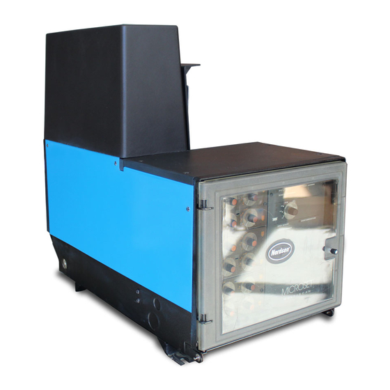
This section covers the following unit configurations.
Model
Voltage
Manifold
Control
41-3000
Issued 11/00
3400
3500
3700
3860
3890
3960
1, 2
DC Gear (O, R, S, T, U, or W)
4-Port (J or F)
6-Port (K, L, O, or P)
2-Port (R or U)
MultiScan (3)
B2EN-02-[3-PUMP]-5
Advertisement
Table of Contents

Related Manuals for Nordson 3400


Summary of Contents for Nordson 3400
- Page 1 1, 2 Pump DC Gear (O, R, S, T, U, or W) Manifold 4-Port (J or F) 6-Port (K, L, O, or P) 2-Port (R or U) Control MultiScan (3) E 2000 Nordson Corporation B2EN-02-[3-PUMP]-5 41-3000 All rights reserved Issued 11/00...
- Page 2 B 2-0 Pump E 2000 Nordson Corporation B2EN-02-[3-PUMP]-5 41-3000 All rights reserved Issued 11/00...
- Page 3 Refer to the Parts section for the part number of any pump component that needs to be replaced. If you try all the suggestions in this section and still cannot solve the problem, call your Nordson representative for assistance. Refer to the Control System section for troubleshooting procedures and repair procedures for the melter’s control system, including the...
- Page 4 Insulate the joints. joints Guns not operating properly Refer to the gun manual to troubleshoot gun problems. Manifold heat exchanger blocked Check manifold heat exchanger for blockage. Clean if necessary. E 2000 Nordson Corporation B2EN-02-[3-PUMP]-5 41-3000 All rights reserved Issued 11/00...
- Page 5 Change to a compatible higher-viscosity adhesive. Nozzle orifice too large for Change to a nozzle with a smaller application orifice. Too much hydraulic pressure Decrease hydraulic pressure. Continued on next page E 2000 Nordson Corporation B2EN-02-[3-PUMP]-5 41-3000 All rights reserved Issued 11/00...
- Page 6 System in the Maintenance section. Do not exceed the recommended adhesive pot life. Adhesive overheated Clean the system. Refer to Cleaning the System in the Maintenance section. Decrease the operating temperature setpoints. E 2000 Nordson Corporation B2EN-02-[3-PUMP]-5 41-3000 All rights reserved Issued 11/00...
- Page 7 Check the tank operating temperature smoking setpoint and adjust it as necessary. Unstable adhesive Keep the lid closed when the melter is operating. Change to a more stable adhesive. Continued on next page E 2000 Nordson Corporation B2EN-02-[3-PUMP]-5 41-3000 All rights reserved Issued 11/00...
- Page 8 Keep the tank at least half full of adhesive. Refer to Adhesive Filling in the Operation section. Nozzles clogged Clean the nozzles. Refer to the nozzle cleaning procedure in your gun manual. E 2000 Nordson Corporation B2EN-02-[3-PUMP]-5 41-3000 All rights reserved Issued 11/00...
- Page 9 A+ (red wire no. 31) and A- (black wire no. 31) wires. If the voltage is less than 10 VDC, replace the motor drive board. Continued on next page E 2000 Nordson Corporation B2EN-02-[3-PUMP]-5 41-3000 All rights reserved Issued 11/00...
- Page 10 16 and 10. If the voltage is 1.0–2.0 VDC, replace the motor control interface board. If the voltage is outside 1.0–2.0 VDC, replace the motor control board. E 2000 Nordson Corporation B2EN-02-[3-PUMP]-5 41-3000 All rights reserved Issued 11/00...
- Page 11 Drive shaft rotates: drain the tank so the adhesive level is lower than the pump mount. Remove the pump. Check the drive shaft coupling. If the coupling is worn or damaged, replace it. If the coupling is okay, replace the pump. E 2000 Nordson Corporation B2EN-02-[3-PUMP]-5 41-3000 All rights reserved...
- Page 12 4. Place the melter circuit breaker in the OFF position, disconnect and lock out electrical power to the melter at the branch circuit disconnect switch, and disconnect and lock out electrical power supplied through any I/O wiring. E 2000 Nordson Corporation B2EN-02-[3-PUMP]-5 41-3000 All rights reserved...
- Page 13 Removing the Pump from the Melter 1. Hopper and drive covers 4. Speed reducer sprocket 2. Upper bearing mount 5. Speed reducer screw 3. Drive chain 6. Chain-tensioning screw E 2000 Nordson Corporation B2EN-02-[3-PUMP]-5 41-3000 All rights reserved Issued 11/00...
- Page 14 2. Remove the return tube (7) and the crossover tube (5). 3. Check the crossover tube O-ring (6) for damage. Replace the O-ring if necessary. NOTE: Nordson Corporation recommends replacing the crossover tube O-ring any time the pump is removed. 4130903A Fig.
- Page 15 6. Idler shaft 2. Steel ball (one of two) 7. Top plate 3. Bottom plate 8. Socket-head screw (one of four) 4. Center plate 9. Dowel pins 5. Spur gears E 2000 Nordson Corporation B2EN-02-[3-PUMP]-5 41-3000 All rights reserved Issued 11/00...
- Page 16 Components WARNING: Risk of fire or explosion. Do not heat Nordson Type-R cleaning fluid above 246 °C (475 °F). Do not heat cleaning fluid with an open flame or in an unregulated heating device.
- Page 17 3. Key 4. Sprocket 5. Drive shaft 6. Key 7. Coupling 8. Lower bearing 9. Retaining ring 10. Seal 11. Pump mount Note: Some items shown for reference only. E 2000 Nordson Corporation B2EN-02-[3-PUMP]-5 41-3000 All rights reserved Issued 11/00...
- Page 18 If the chain becomes too tight, loosen the same screws and turn the chain-tensioning screw counterclockwise. Move the speed reducer to decrease the chain tension. E 2000 Nordson Corporation B2EN-02-[3-PUMP]-5 41-3000 All rights reserved...
- Page 19 (0.08–0.12 in.) (0.08–0.12 in.) 4130914A Fig. B 2-5 Chain Tension/Deflection 1. Chain-tensioning screw 2. Tight chain 7. Reinstall the hopper and drive covers. 8. Restore the system to normal operation. E 2000 Nordson Corporation B2EN-02-[3-PUMP]-5 41-3000 All rights reserved Issued 11/00...
- Page 20 Replacing the Motor 1. Motor 2. Speed reducer coupling 6. Attach the new motor to the speed reducer. Tighten the screws, washers, and lock washers to 6.78–8.14 NSm (5–6 ft-lb). E 2000 Nordson Corporation B2EN-02-[3-PUMP]-5 41-3000 All rights reserved Issued 11/00...
- Page 21 (7) to separate the speed reducer from the spacers (9), the motor support bracket (10), and the adjusting bracket (12). 5. Remove the drive chain (3) from the speed reducer sprocket (5). E 2000 Nordson Corporation B2EN-02-[3-PUMP]-5 41-3000...
- Page 22 7. Speed reducer screw 2. Motor 8. Speed reducer 3. Coupling 9. Spacer 4. Drive chain 10. Motor support bracket 5. Sprocket 11. Chain-tensioning screw and nut 6. Key 12. Adjusting bracket E 2000 Nordson Corporation B2EN-02-[3-PUMP]-5 41-3000 All rights reserved Issued 11/00...
- Page 23 If the chain becomes too tight, loosen the same screws and turn the chain-tensioning screw counterclockwise. Move the speed reducer to decrease the chain tension. E 2000 Nordson Corporation B2EN-02-[3-PUMP]-5 41-3000 All rights reserved...
- Page 24 2.0–2.9 mm (0.08–0.12 in.) (0.08–0.12 in.) 4130914A Fig. B 2-8 Chain Tension/Deflection 1. Chain-tensioning screw 2. Tight chain 10. Reinstall the drive cover. 11. Restore the system to normal operation. E 2000 Nordson Corporation B2EN-02-[3-PUMP]-5 41-3000 All rights reserved Issued 11/00...
Need help?
Do you have a question about the 3400 and is the answer not in the manual?
Questions and answers