Table of Contents
Advertisement
Quick Links
2007-2013 Yamaha Grizzly 700
I n s t a l l a t i o n I n s t r u c t i o n s
PLEASE READ ALL DIRECTIONS BEFORE STARTING INSTALLATION
22-027
www.powercommander.com
2191 Mendenhall Drive North Las Vegas, NV 89081 (800) 992-4993 www.powercommander.com
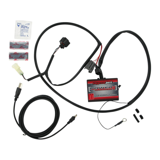
PARTS LIST
1
Power Commander
1
USB Cable
1
CD-ROM
1
Installation Guide
2
Power Commander Decals
2
Dynojet Decals
2
Velcro
1
Alcohol swab
THE IGNITION MUST BE TURNED
OFF BEFORE INSTALLATION!
YOU CAN ALSO DOWNLOAD THE
POWER COMMANDER SOFTWARE AND
LATEST MAPS FROM OUR WEB SITE AT:
www.powercommander.com
2007-2013 Yamaha Grizzly 700 PCV - 1
Advertisement
Table of Contents

Related Manuals for Dynojet Power Commander V 22-027


Summary of Contents for Dynojet Power Commander V 22-027
- Page 1 2007-2013 Yamaha Grizzly 700 CD-ROM Installation Guide I n s t a l l a t i o n I n s t r u c t i o n s Power Commander Decals Dynojet Decals Velcro Alcohol swab THE IGNITION MUST BE TURNED OFF BEFORE INSTALLATION!
- Page 2 ACCESSORY INPUTS Map - (Input 1 or 2) The PCV has the ability to hold 2 different base maps. You can switch on the fly between these two base maps when you hook up a switch to the MAP inputs. You can USB CONNECTION use any open/close type switch. The polarity of the wires is not important. When using the Autotune kit one position will hold a base map and the other position will let you activate the learning mode. When the switch is “CLOSED” Autotune will be activated. (Input 1 or 2) These inputs are for use with the Shifter- Dynojet quickshifter. Insert the wires from the Dynojet quickshifter into the SHIFTER inputs. CRANK The polarity of the wires is not important. ANALOG Speed- If your application has a speed sensor then SPEED you can tap into the signal side of the sensor EXPANSION PORTS 1 & 2 INPUT 2 (Grnd) and run a wire into this input. This will allow you to calculate gear position in the Control INPUT 2 Optional Accessories such as Center Software. Once gear position is setup...
- Page 3 FIG.A Remove the seat. Remove the front cover (Fig. A). Remove this cover FIG.B Remove the right hand side cover (Fig. B) and the same cover on the left side. Ground wire FIG.C Remove Remove the intake tube for the CVT clutch on the right hand side of the quad (Fig. C). This allows access to the Throttle Position Sensor 22-027 www.powercommander.com 2007-2013 Yamaha Grizzly 700 PCV - 3...
- Page 4 FIG.D Unplug the stock wiring harness from the injector (Fig. D). Unplug Figure D was taken from the left hand side of the quad. FIG.E Place the PCV in the battery area temporarily. Route the PCV harness down the left hand side of the Quad towards the throttle body. Plug the PCV in-line of the stock wiring harness and injector (Fig. E). FIG.F Unplug Locate the Throttle Position Sensor on the right hand side of the throttle body. 10 Unplug the stock wiring harness from the TPS (Fig. F). 22-027 www.powercommander.com 2007-2013 Yamaha Grizzly 700 PCV - 4...
- Page 5 FIG.G 11 Plug the wiring harness from the PCV in-line of the stock wiring harness and TPS (Fig. G). FIG.H 12 Attach the ground wire from the PCV to the negative side of the battery (Fig. H). Ground wire FIG.J 13 Install the included port covers onto your PCV. 14 Secure the PCV near the battery using the supplied Velcro (Fig. J). Make sure to use the alcohol swab to clean both surfaces before attaching. 15 Reinstall bodywork. 22-027 www.powercommander.com 2007-2013 Yamaha Grizzly 700 PCV - 5...
Need help?
Do you have a question about the Power Commander V 22-027 and is the answer not in the manual?
Questions and answers