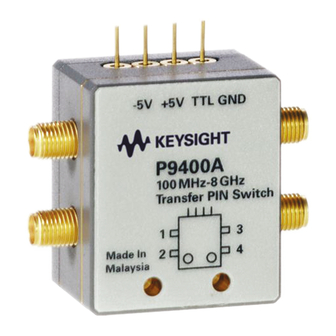
Summary of Contents for Keysight P9400A
- Page 1 Keysight P9400A/C Solid State PIN Diode Transfer Switch Operating and Service Guide...
- Page 2 Conformity. understood and met. where in the EULA. Keysight shall be under no obligation to update, revise or otherwise modify the Software. With WARNING respect to any technical data as defined by FAR 2.101, pursuant to FAR...
-
Page 3: Waste Electrical And Electronic Equipment Directive 2002/96/Ec
Printing Copies of this Document To print copies of this document, download the PDF from the Keysight website: – Visit www.keysight.com. – Enter the document’s part number (see page 2) in the Search box. – Click GO. -
Page 4: Sales And Technical Support
Sales and Technical Support To contact Keysight for sales and technical support, refer to the support links on the following Keysight websites: – www.keysight.com/find/switches (product-specific information and support, software and documentation updates) – www.keysight.com/find/assist (worldwide contact information for repair and service) -
Page 5: Table Of Contents
........18 Keysight P9400A/C Operating and Service Guide... - Page 6 THIS PAGE HAS BEEN INTENTIONALLY LEFT BLANK Keysight P9400A/C Operating and Service Guide...
- Page 7 Keysight P9400A/C PIN Transfer Switch Operating and Service Guide General Information Product Overview Key Features Circuit Logic This chapter provides an overview specifications of Keysight solid state PIN diode transfer switches.
-
Page 8: General Information
The P9400A/C switches consist of series PIN diode switch IC and multiple shunt PIN diodes which offer unmatched isolation between ports. Ultra fast switching speed of <200 ns assures fast, reliable and accurate switching that is compatible with today’s high demand for superior RF performance system. -
Page 9: Key Features
– Increase test setup flexibility with a broad operating frequency range – Increase test throughput effectively with high–speed switching time of <200 ns – Optimize system dynamic range with low insertion loss – Eliminate the need for external drivers with integrated TTL-compatible driver Keysight P9400A/C Operating and Service Guide... -
Page 10: Circuit Logic
General Information Circuit Logic Keysight P9400A/C switches come with integrated TTL- compatible driver that is configured in such a way that when a TTL high (logic 1) is applied to TTL pin of the switch, the paths from Port 1 to Port 2 and Port 3 to Port 4 of the switch are at low loss, while the paths from Port 1 to Port 3 and Port 2 to Port 4 are at high isolation. - Page 11 General Information Figure 1-3 Diagram of P9400A/C Switches in State B Keysight P9400A/C Operating and Service Guide...
- Page 12 General Information THIS PAGE HAS BEEN INTENTIONALLY LEFT BLANK Keysight P9400A/C Operating and Service Guide...
-
Page 13: Specifications
Keysight P9400A/C PIN Transfer Switch Operating and Service Guide Specifications For the characteristics and specifications of the P9400A/C switches, refer to the Technical Overview document at https://literature.cdn.keysight.com/litweb/pdf/5989-7215EN.pdf. - Page 14 Specifications THIS PAGE HAS BEEN INTENTIONALLY LEFT BLANK Keysight P9400A/C Operating and Service Guide...
- Page 15 Operating and Service Instruction This chapter describes the installation of the P9400A/C. The operating instruction quick- check procedure is included for verification test prior to usage. Service instructions on the repair and maintenance of the P9400A/C are also included in this chapter.
-
Page 16: Installation
“Sales and Technical Support” on page 4). Keysight will arrange for repair or replacement of the damaged or defective equipment. Keep the shipping materials for the carrier’s inspection. 3 If you are returning the instrument under warranty or for service, repackaging the instrument requires original shipping containers and materials or their equivalents. -
Page 17: Operating And Service Instruction
4 Repeat Step 2 and 3 for Port 3 and Port 4 of the switch. 5 Repeat Step 2 and 3 for Port 1 and Port 3 of the switch by applying logic ‘0’ (0 V to +0.8 V) to TTL. Keysight P9400A/C Operating and Service Guide... -
Page 18: Performance Test
The solid state PIN diode transfer switches do not have internal adjustments and should not be opened. Repair The P9400A/C solid state PIN diode transfer switches are not recommended for repair as most components cannot be easily removed. Keysight P9400A/C Operating and Service Guide... - Page 19 Installation Maintenance The connectors, particularly the connector faces, must be kept clean. For instruction on connecting and care of your connectors, refer to the Microwave Connector Care Quick Reference Card (08510-90360). Keysight P9400A/C Operating and Service Guide...
- Page 20 Installation THIS PAGE HAS BEEN INTENTIONALLY LEFT BLANK Keysight P9400A/C Operating and Service Guide...
- Page 21 This information is subject to change without notice. Always refer to the English version at the Keysight website for the latest revision. © Keysight Technologies 2019 Edition 4, April 9, 2019 Printed in Malaysia P9400-90001 www.keysight.com...


Need help?
Do you have a question about the P9400A and is the answer not in the manual?
Questions and answers