Graco EM5 Series Instructions And Parts List
Electronic metered dispense valves
Hide thumbs
Also See for EM5 Series:
- Instructions-parts list manual (23 pages) ,
- Quick reference manual (4 pages) ,
- Instructions manual (24 pages)
Advertisement
Quick Links
INSTRUCTIONS-PARTS LIST
This manual contains important
warnings and information.
READ AND KEEP FOR REFERENCE.
INSTRUCTIONS
Standard
EM5
Electronic Metered
Dispense Valves
1000 psi (69 bar) Maximum Working Pressure
Maximum Flow Rate 5 gpm (18.9 lpm)
Unit of Measurement: Quarts
Model 238–451
75 Bend 3/8-in. Rigid Tube
Model 238–452
3/8-in Coupled Flexible Hose
Model 238–453
15 Bend 3/8-in. Gear Lube Tube with 90 Elbow
Unit of Measurement: Liters
Model 238–454
75 Bend 3/8-in. Rigid Tube
Model 238–455
3/8-in Coupled Flexible Hose
Model 238–456
15 Bend 3/8-in. Gear Lube Tube with 90 Elbow
CAUTION
These dispense valves are designed to
dispense petroleum-based lubricants and
antifreeze only.
These dispense valves are designed for indoor
use only. If used outdoors, they must be
sheltered from the rain.
EXIA
Intrinsically safe
Class I,
Division 1,
Groups C, D
Hazardous Locations
GRACO INC. P.O. BOX 1441 MINNEAPOLIS, MN 55440–1441
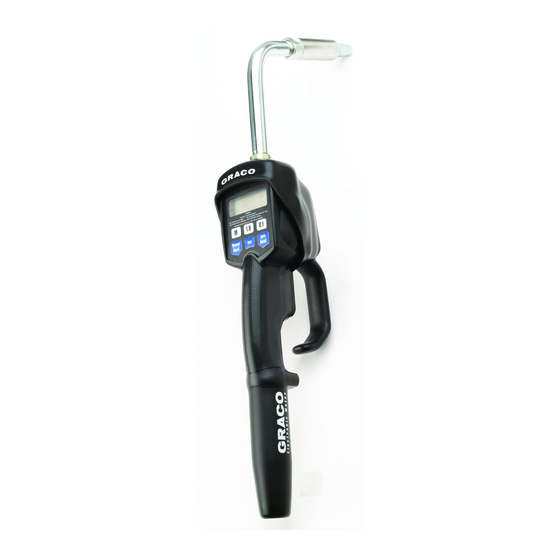
Model 238–451 shown
COPYRIGHT 1996, GRACO INC.
Graco Inc. is registered to I.S. EN ISO 9001
308–487
Rev. A
Advertisement

Related Manuals for Graco EM5 Series


Summary of Contents for Graco EM5 Series
- Page 1 Model 238–451 shown EXIA Intrinsically safe Class I, Division 1, Groups C, D Hazardous Locations GRACO INC. P.O. BOX 1441 MINNEAPOLIS, MN 55440–1441 COPYRIGHT 1996, GRACO INC. Graco Inc. is registered to I.S. EN ISO 9001...
- Page 2 This equipment is for professional use only. Read all instruction manuals, tags, and labels before you operate this equipment. Use the equipment only for its intended purpose. If you are not sure, call your Graco distributor. Do not alter or modify this equipment.
- Page 3 FIRE AND EXPLOSION HAZARD Improper grounding, poor ventilation, open flames, or sparks can cause a hazardous condition and result in a fire or explosion and serious injury. Be sure the entire fluid system is properly grounded. Refer to your pump instruction manual for complete details.
- Page 4 Additionally, these dispense valves can be installed on a console, as shown in Fig. 2. Do not use this electronic metered dispense valve on non-Graco consoles. Such use could result in the trigger becoming inadvertently pressed while the dispense valve is stowed.
- Page 5 Installation Pre-Installation Procedure 8. Loosen and disconnect the hose from the old dispense valve (the one that you are replacing). 1. Relieve the pressure. 9. Slide the swivel cover (4) onto the hose, small end first. See Fig. 3. 10. Apply thread sealant to the the male threads of the To reduce the risk of serious injury whenever you hose fitting, thread the hose fitting into the swivel are instructed to relieve pressure, always follow the...
- Page 6 Installation Grounding Model shown has Proper grounding is an essential part of maintaining a a 75 bend rigid safe system. extension (5). To reduce the risk of static sparking, ground all system components per local and national electrical codes. hose Refer to the user manuals for the pump and other system components to ground the following: 1.
- Page 7 Operation 2. If you do not want to reset the total, skip this step 6. If you do not want to change the auto preset by pressing the Auto button. If you want to reset amount, skip this step by pressing the Auto button. the total, press the Reset button.
- Page 8 Operation 7. Press the Auto button. Dispensing Fluid The reset-to-zero indicator (clock icon) is shown These are the procedures for dispensing fluid in on the display, along with either On or OFF, as Standard mode and Preset mode. shown below. On means that the unit will automatically reset to zero after two minutes of Standard Mode inactivity.
- Page 9 Operation Preset Mode Viewing Totals and the Calibration Factor NOTE: All buttons are disabled while fluid is being This is the procedure for viewing the non-resettable dispensed. and resettable totals in the current units and for viewing the calibration factor. 1.
- Page 10 Operation 3. Press the Total button again. 5. Press the Reset button. The resettable total amount is shown on the The unit returns to Normal mode, and the Normal display in the current units, as shown below. mode display is shown. Error Codes If, after a dispensing cycle, you see an error code on 00000...
- Page 11 Operation Calculating the Calibration Factor Use the following tables and formulas to calculate the change to make to the calibration factor. Example of Calibration Factor Change Dispense 1,000 milliliters, with the amount displayed, into a clean calibrated volumetric measuring flask. For increased accuracy, submerge the nozzle, and let the air settle out of the fluid for ten minutes before you note the volume.
- Page 12 Operation Calibrating the Meter NOTE: This unit has been calibrated at the factory to 06815 dispense lubricating oils; it should not require additional calibration during installation. If this unit will be used to dispense antifreeze, and accuracy must be greater than plus or minus 2 percent, it is recommended that you use a calibration factor of 7230.
- Page 13 Filter(s) are clogged. 1. Relieve the pressure. 2. Clean the filters. Pump pressure is low. 3. If the problem remains, contact your Graco distributor for repair or replacement. Shutoff valve is not fully open. Foreign material is jammed in the metering element.
- Page 14 Service Replacing the Battery Valve Repair Kit See the Parts List on page 16 and the Parts Drawing on page 17. The parts with asterisks next to their reference numbers are available in the Valve Repair Do not change the battery while anything is Kit, which can be ordered separately.
- Page 15 Service Replacing the Dripless Nozzle Security Seal Option If the dripless nozzle (5b, 6b, or 7b) begins to leak, The security seal option is used to prevent access to replace it as follows: the inside of the meter and tampering with the meter settings.
- Page 16 Parts List Ref. Ref. No. Part No. Description Qty. No. Part No. Description Qty. 238–552 COVER/CONTROL 113–716 BATTERY; standard 9V, alkaline includes battery (8) and 113–419 NUT, seal; 3/8–18 NPT battery cover (2) (Models 238–451, 238–453, 238–454, and 238–456 only) 191–351 COVER, battery 238–422...
- Page 17 Parts Drawing Torque to 7 to 10 in-lb (0.79 to 1.13 N.m). Torque to 140 to 150 in-lb (15.8 to 16.9 N.m). Apply lubricant when reassembling. Site glass (Part No. 238–372) may be purchased separately. Street elbow 155–699 is included with nozzle assembly 238–886 for an optional 90 bend before the flexible extension.
- Page 18 Technical Data Flow range* ......0.26 to 5 gpm Meter valve assembly pressure loss (At 1.5 gpm [5.7 lpm] with 30-weight oil (1 to 18.9 lpm) Operating pressure range .
- Page 19 Notes...
- Page 20 Graco distributor to the original purchaser for use. As purchaser’s sole remedy for breach of this warranty, Graco will, for a period of two (2) years from the date of sale, repair or replace any part of the equipment proven defective, with the exception of defects in the electronic meter control, including the battery, which will be repaired or replaced for twelve (12) months from the date of sale.
Need help?
Do you have a question about the EM5 Series and is the answer not in the manual?
Questions and answers