Table of Contents
Advertisement
Quick Links
Nu-Link2-Pro Debugger and Programmer
Nu-Link2-Pro
Debugger and Programmer
User Manual
The information described in this document is the exclusive intellectual property of
Nuvoton Technology Corporation and shall not be reproduced without permission from Nuvoton.
Nuvoton is providing this document only for reference purposes of NuMicro microcontroller based system
design. Nuvoton assumes no responsibility for errors or omissions.
All data and specifications are subject to change without notice.
For additional information or questions, please contact: Nuvoton Technology Corporation.
www.nuvoton.com
Mar. 13, 2020
Page 1 of 77
Rev 1.00
Advertisement
Table of Contents

Related Manuals for Nuvoton Nu-Link2-Pro


Summary of Contents for Nuvoton Nu-Link2-Pro
- Page 1 The information described in this document is the exclusive intellectual property of Nuvoton Technology Corporation and shall not be reproduced without permission from Nuvoton. Nuvoton is providing this document only for reference purposes of NuMicro microcontroller based system design. Nuvoton assumes no responsibility for errors or omissions.
-
Page 2: Table Of Contents
Nu-Link2-Pro Debugger and Programmer Table of Contents INTRODUCTION ................8 Nu-Link2-Pro Features ............... 9 GETTING STARTED WITH NU-LINK2-PRO ........10 Nu-Link2-Pro Kit Contents ..............10 Nu-Link2-Pro PCBA .................11 Nu-Link2-Pro Overview ..............12 CONNECTING THE NU-LINK2-PRO ..........14 Nu-Link2-Pro Compatible Extension Connectors ........14 SWD Interface Pin Definition and Function Connection .......15... - Page 3 Keil MDK ..................... 44 IAR EWARM ..................53 NuEclipse GCC ..................58 ISP Tool ....................65 More Features of Nu-Link2-Pro Firmware ............69 Appendix .................. 71 Nu-Link2-Pro Operating Current of ICP ..........71 Nu-Link2-Pro Operating Current of ISP ..........72 Automatic IC Programming System ............73 Operation Sequence and Waveform ............
- Page 4 Figure 5.2-3 Select One Nu-Link2-Pro ................... 41 Figure 5.2-4 ICP Tool Programming Options ................. 41 Figure 5.2-5 Nu-Link2-Pro Connected with a Target Chip Detected ..........42 Figure 5.2-6 Nu-Link2-Pro Connected with No Target Chip Detected........... 42 Figure 5.2-7 Programming File Selection Window................. 43 Figure 5.2-8 Programming Completion Window ................
- Page 5 Figure 5.2-13 Programming Setting in Options Window ..............46 Figure 5.2-14 Nu-Link2-Pro Parameter Settings................46 Figure 5.2-15 Keil MDK Programmer Selection ................47 Figure 5.2-16 Nu-Link2-Pro Programming Settings ............... 47 Figure 5.2-17 Compile and Download the Project ................. 48 Figure 5.2-18 Keil MDK Debug Mode .................... 48 Figure 5.2-19 Debug Message on Serial Port Terminal Windows ..........
- Page 6 Nu-Link2-Pro Debugger and Programmer Figure 5.2-46 Debug Message on Serial Port Terminal Windows ..........64 Figure 5.2-47 Startup Screen of ISP Tool ..................65 Figure 5.2-48 ISP is not connected to any device of ISP Tool ............65 Figure 5.2-49 ISP Firmware Sample Code Project ................ 66 Figure 5.2-50 Boot from LDROM Setting in Keil ISP Firmware Project .........
- Page 7 Table 6.1-2 Nu-Link2-Pro Operating Current (Offline Programming) of SPI Flash ....... 71 Table 6.1-3 Nu-Link2-Pro Operating Current (Offline Programming) of USB Flash ...... 71 Table 6.1-4 Nu-Link2-Pro Operating Current (Offline Programming) of Micro SD Card ....71 Table 6.2-1 Operating Current of ISP Online Programming ............72 Table 6.1-1 Comparison of All Nu-Link Debugger and Programmer ..........
-
Page 8: Introduction
Family programming microcontrollers are supported by a diverse range of IDEs, such as Keil MDK, IAR EWARM, and NuEclipse GCC. With the Nu-Link2-Pro, users can program and debug directly on IDEs with full access and visibility into the microcontrollers. ®... -
Page 9: Nu-Link2-Pro Features
Nu-Link2-Pro Debugger and Programmer Nu-Link2-Pro Features ® Supports programming and debugging of all NuMicro Family microcontrollers Supports In-Circuit Programming (ICP) Selectable SWD output voltage (1.8 V / 2.5 V / 3.3 V / 5.0 V) ICP Programming Tool with image file protection ... -
Page 10: Getting Started With Nu-Link2-Pro
4. SWD cable 5. Bridge cable 1. Nu-Link2-Pro 3. ETM cable 2. USB cable Figure 2.1-1 Nu-Link2-Pro Full Kit Contents Figure 2.1-1 shows the contents of Nu-Link2-Pro full kit: Nu-Link2-Pro main body (2952mil x 1968mil x 688mil) USB cable (0.3m, high-speed, Micro-B) ... -
Page 11: Nu-Link2-Pro Pcba
SWD Connector Bridge Connector Figure 2.2-1 Front View of Nu-Link2-Pro PCBA Figure 2.2-1 shows the main components and connectors from the front side of Nu-Link2-Pro PCBA. The following lists components and connectors from the front view: Main Chip: M48SKIDAE ... -
Page 12: Nu-Link2-Pro Overview
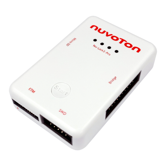
Start Button Bridge Connector ETM Connector SWD Connector Figure 2.3-1 Nu-Link2-Pro Connector and Function Overview Figure 2.3-1 shows the Nu-Link2-Pro profile and connector overview, the following lists of function brief description USB Connector (CON5) USB Flash Drive for ICP Offline Programming ... -
Page 13: Table 2.3-1 Status Leds Difference List
Click this button to proceed with offline programming Micro SD Card Slot Save bin file for ICP Offline Programming Status LED (ICES0, ICES1, ICES2, ICES3) Display the operation status of the Nu-Link2-Pro Status LED Nu-Link2-Pro Operation Status Green Boot Flash×3 Flash×3 Flash×3 Flash×3... -
Page 14: Connecting The Nu-Link2-Pro
Nu-Link2-Pro Debugger and Programmer CONNECTING THE NU-LINK2-PRO This chapter introduces how to connect the Nu-Link2-Pro to a computer, and how to connect individual connectors to development board or products. Nu-Link2-Pro Compatible Extension Connectors Figure 3.1-1 shows the Nu-Link2-Pro definition pin of each connector, the Nu-Link2-Pro mainly contains USB, Micro USB, Bridge interface, ETM interface and SWD interface. -
Page 15: Swd Interface Pin Definition And Function Connection
Nu-Link2-Pro Debugger and Programmer SWD Interface Pin Definition and Function Connection Table 3.2-1 shows SWD interface pin definition and description. The Nu-Link2-Pro provides a SWD interface connector with a 100-mil 10-pin cable. The SWD supports ICE Programming, Virtual COM and automatic IC Programming. -
Page 16: Virtual Com Connection
Corresponding Pin for ICE Virtual COM Connection The Nu-Link2-Pro provides virtual COM port (VCOM) function to print out messages on PC, and the Virtual COM transmission data by UART0. The connection pins are VCC (CON4.1), VSS (CON4.9), TX (CON4.8) and RX (CON4.10). Figure 3.2-2 presents how to connect the target board to use VCOM and Table 3.2-3 shows the pin corresponding to the target board. -
Page 17: Automatic Ic Programming Connection
Corresponding Pin for Virtual COM Automatic IC Programming Connection The Nu-Link2-Pro provides Automatic IC Programming function to mass production. The Automatic IC Programming connection pins are VCC (CON4.1), VSS (CON4.9), BUSY (CON4.2), START (CON4.4), PASS (CON4.8) and FAIL (CON4.10). Figure 3.2-3 presents how to connect the target board to use Automatic IC Programming and Table 3.2-4 shows the pin corresponding to the target board. -
Page 18: Figure 3.2-3 Swd Interface Connection Diagram For Automatic Ic Programming
PASS CON4.8 PASS VSS(GND) CON4.9 VSS(GND) FAIL CON4.10 FAIL Note: The target board power setting should be the same as Nu-Link2-Pro. Table 3.2-4 SWD Interface Corresponding Pin for Automatic IC Programming Mar. 13, 2020 Page 18 of 77 Rev 1.00... -
Page 19: Bridge Interface Pin Definition And Function Connection
Nu-Link2-Pro Debugger and Programmer Bridge Interface Pin Definition and Function Connection Table 3.3-1 shows the bridge interface pin definition and description. The Nu-Link2-Pro provides a bridge interface connector with a 100-mil 20-pin cable. The bridge interface supports one channel UART, I C, SPI, RS-485, CAN BUS, ADC, PWM and two GPIOs. -
Page 20: I 2 C Connection
CON6.18 VSS(GND) VSS(GND) CON6.20 VSS(GND) Note: The target board power and signal only supports 3.3V at Nu-Link2-Pro Bridge interface. Table 3.3-2 Bridge Interface Corresponding Pin for UART C Connection The Nu-Link2-Pro provides one channel I C function for monitor mode receive information, and print out Mar. -
Page 21: Figure 3.3-2 Bridge Interface Connection Diagram For I 2 C
CON6.20 VSS(GND) Note: 1. Internal 4.7 kΩ pull-up resistors R67 and R68 on Nu-Link2-Pro; the user can adjust them according to needs. 2. The target board power and signal only support 3.3 V at Nu-Link2-Pro Bridge interface. Interface Table 3.3-3 Bridge Pin for I Mar. -
Page 22: Spi Connection
Nu-Link2-Pro Debugger and Programmer SPI Connection The Nu-Link2-Pro provides one channel SPI function for monitor mode receive information, and print out information by UART. The SPI connection pins are VCC33(CON6.14 and CON6.16), VSS (CON6.18 and CON6.20), SS(CON6.5), CLK(CON6.6), MOSI(CON6.7) and MISO(CON6.8). Figure 3.3-3 presents how to connect the target board to use SPI function and Table 3.3-4 shows the pin corresponding to the... -
Page 23: Rs-485 Connection
Nu-Link2-Pro Debugger and Programmer VSS (GND) CON6.20 VSS (GND) Note: The target board power and signal only support 3.3 V at Nu-Link2-Pro Bridge interface. Interface Table 3.3-4 Bridge Corresponding Pin for SPI RS-485 Connection The Nu-Link2-Pro provides one channel RS-485 function for monitor mode receive information, and print out information by UART. -
Page 24: Can Bus Connection
VSS(GND) CON6.20 VSS(GND) Note: Internal 120 Ω terminal resistors R62 on Nu-Link2-Pro; the user can adjust them according to needs. The target board power and signal only support 3.3 V at Nu-Link2-Pro Bridge interface. Table 3.3-5 Bridge Interface Corresponding Pin for RS-485... -
Page 25: Pwm And Capture
VSS(GND) CON6.20 VSS(GND) Note: Internal 120 Ω terminal resistors R63 on Nu-Link2-Pro; the user can self-adjust them according to needs. The target board power and signal only support 3.3 V at Nu-Link2-Pro Bridge interface. Table 3.3-6 Bridge Interface Corresponding Pin for CAN BUS PWM and Capture The Nu-Link2-Pro provides one channel PWM function for user flexible planning. -
Page 26: Adc Connection
Corresponding Pin for PWM ADC Connection The Nu-Link2-Pro provides one channel ADC function for user flexible planning. The ADC connection pins are VCC33(CON6.14 and CON6.16), VSS(CON6.18 and CON6.20) and ADC(CON6.13). Figure 3.3-7 presents how to connect the target board to use ADC function and Table 3.3-8 shows the pin corresponding to the target board. -
Page 27: Gpio Connection
Corresponding Pin for ADC GPIO Connection The Nu-Link2-Pro provides two channel GPIO function for user flexible planning. The GPIO connection pins are VCC33(CON6.14 and CON6.16), VSS(CON6.18 and CON6.20), GPIO0(CON6.17) and GPIO1(CON6.19). Figure 3.3-8 presents how to connect the target board to use GPIO function and Table 3.3-9 shows the pin corresponding to the target board. -
Page 28: Table 3.3-9 Bridge Interface Corresponding Pin For Gpio
CON6.14 VCC33 CON6.16 VSS(GND) CON6.18 VSS(GND) VSS(GND) CON6.20 VSS(GND) Note: The target board power and signal only support 3.3V at Nu-Link2-Pro Bridge interface. Interface Table 3.3-9 Bridge Corresponding Pin for GPIO Mar. 13, 2020 Page 28 of 77 Rev 1.00... -
Page 29: Etm Interface Pin Definition And Function Connection
Nu-Link2-Pro Debugger and Programmer ETM Interface Pin Definition and Function Connection Table 3.4-1 shows ETM interface pin definition and description. The Nu-Link2-Pro provide a ETM interface connector with a 50-mil 20-pin cable. The ETM interface supports ETM and SWD function. The following sections will introduce the definition of the ETM interface pin and the connected of each function. -
Page 30: Etm Connection
ETM function. ICP Offline Programming Function Connection The Nu-Link2-Pro provides three kinds storage interface for Nu-Link2-Pro ICP offline programming. The user can save the bin file to USB Flash drive, Micro SD card or SPI Flash for offline programming. The priority of reading from these three storage is USB Flash drive >... -
Page 31: Figure 3.5-1 Icp Offline Programming Illustration Of Swd Interface
Nu-Link2-Pro Debugger and Programmer 1. USB Flash drive 2. Micro SD card 3. SPI Flash Micro USB Programming Tool ICP Offline Programming NuMicro® Family Target Board BUSY ICE_DAT START ICE_CLK /RESET PASS/RX VSS(GND) FAIL/TX Figure 3.5-1 ICP Offline Programming Illustration of SWD Interface Mar. -
Page 32: Debugging And Programming
In Debug mode, the user can add breakpoints in the code for debugging. During the real-time simulation of the Nu-Link2-Pro, the chip simulation will be stopped at a specific breakpoint. Figure 4.1-1 shows the breakpoint settings in Keil MDK Debug mode. The red labels on lines 052 and 059 indicate the breakpoints inserted;... -
Page 33: Figure 4.1-2 System Viewer Control Related Options In Keil Mdk Debug Mode
Detailed Operation: Double-clicking a “register name” will open the register control details, as shown in Figure 4.1-3. The “register value” can be modified directly. The Nu-Link2-Pro will modify the content of the target chip. Mar. 13, 2020 Page 33 of 77... -
Page 34: Semihost
When using the Semihost function, the message of the NuMicro Family microcontroller can be output through UART to the debug window by the Nu-Link2-Pro. That is, the message is output without the GPIO. Figure 4.1-4 shows the debug messages in the “UART #1” form, which are the messages output by the Nu-Link2-Pro. -
Page 35: Embedded Trace Macrocell (Etm)
Figure 4.1-4 Semihost Options in Keil MDK Debug Mode Embedded Trace Macrocell (ETM) Nu-Link2-Pro supports the Embedded Trace Macrocell function that can show every single executed section instruction in the current application to PC, For detailed settings and usage, please refer to 5.2.2.3... -
Page 36: Programming
USB flash drive or SD card. 2. Plug USB flash drive or SD card into Nu-Link2-Pro. Pressing the button on the Nu-Link2-Pro will switch the Nu-Link2-Pro to offline download mode and start to download the offline data to target chip immediately. -
Page 37: Isp Online Programming
Nu-Link2-Pro Debugger and Programmer during mass production. For details, please refer to the section 6.3. ® NuMicro Family ICP Tool Program ® NuMicro Family Target Board Nu-Link2-Pro SD Card & USB Flash Figure 4.2-2 Offline Programming Flow Diagram ISP Online Programming... -
Page 38: Wide Voltage Programming
VCC, ICE_DAT, ICE_CLK, and /RESET. Installing the Nu-Link2-Pro Driver The Nu-Link2-Pro supports a variety of functions and third-party software tools (e.g. Keil MDK and IAR EWARM). After the software programs are installed, the drivers are also required. You can use the... -
Page 39: Installation And Setup
3.2 for details. Through a SWD port, the Nu-Link2-Pro can supply power (1.8 V, 2.5 V, 3.3 V, or 5.0 V) to a target circuit board. The maximum is 5 V/500 mA. Refer to Table 6.1-1 for detailed specifications. -
Page 40: Software Setup
Nu-Link2-Pro Debugger and Programmer Software Setup This section briefly describes required software settings for connecting to the Nu-Link2-Pro. For detailed software operation, refer to the related user manuals. ICP Tool ® (1) Download and install Nuvoton NuMicro ICP Programming Tool. -
Page 41: Figure 5.2-3 Select One Nu-Link2-Pro
Nu-Link2-Pro Debugger and Programmer (4) And then click the Connect button. Go to (5) if more than one Nu-Link2-Pro are connected with the host. Go to (6) if only one Nu-Link2-Pro is connected with the host. (5) If two Nu-Link Debugger and Programmers have been connected with the computer, a message appears and asks to select one from the two adapters. -
Page 42: Figure 5.2-5 Nu-Link2-Pro Connected With A Target Chip Detected
Figure 5.2-5 Nu-Link2-Pro Connected with a Target Chip Detected (9) Figure 5.2-6 shows that the ICP Tool has been connected with the Nu-Link2-Pro with no target chip detected. The ICP tool will continue detecting the target chip until the Stop Check button is clicked. -
Page 43: Figure 5.2-7 Programming File Selection Window
Nu-Link2-Pro Debugger and Programmer Figure 5.2-7 Programming File Selection Window Figure 5.2-8 Programming Completion Window Mar. 13, 2020 Page 43 of 77 Rev 1.00... -
Page 44: Keil Mdk
Nu-Link_Keil_Driver for Keil MDK has been downloaded and installed such that the Keil MDK can recognize the Nu-Link2-Pro. (1) Double click the Template.uvproj to open the project. Note: If Figure 5.2-9 warning message jumps out, please migrate to version 5 formats as shown in Figure 5.2-10. -
Page 45: Figure 5.2-11 Enable Debug Information For Keil Mdk
Nu-Link2-Pro Debugger and Programmer Figure 5.2-11 Enable Debug Information for Keil MDK (3) Invoke Project → Options for Target → Debug, and make sure the Use:「Nuvoton Nu-Link Debugger option is checked, as shown in Figure 5.2-12 and Figure 5.2-13. Figure 5.2-12 Debugger Setting in Options Window Mar. -
Page 46: Figure 5.2-13 Programming Setting In Options Window
Nu-Link & Nu-Link-Me & Nu-Link2-Me Figure 5.2-14 Nu-Link2-Pro Parameter Settings Debug Function Description Driver Version Display the Nu-Link2-Pro driver version in the host Chip Type Specify the Target chip type Reset Select Auto detect to reset the target chip Mar. 13, 2020 Page 46 of 77 Rev 1.00... -
Page 47: Figure 5.2-15 Keil Mdk Programmer Selection
Specify the SWD port I/O voltage for the target chip; options include 1.8 V, 2.5 V, 3.3 V, and 5 V Table 5.2-1 Debugger Function Settings Description Nu-Link2-Pro will automatically determine the target chip support voltage. If the voltage only supports 3.3 V, it will automatically set to 3.3 V power supply. Programmer Settings (5) Invoke Project →... -
Page 48: Figure 5.2-17 Compile And Download The Project
Nu-Link2-Pro Debugger and Programmer Click “Start/Stop Debug Section” button can enter debug mode. 1. Rebuild 2. Successfully compile 3. Download 4. Start/Stop Debug Figure 5.2-17 Compile and Download the Project (8) Figure 5.2-18 shows the debug mode under Keil MDK. Click “Run” and the debug message will be printed out as shown in Figure 5.2-19. -
Page 49: Figure 5.2-19 Debug Message On Serial Port Terminal Windows
To start Embedded Trace Macrocell (ETM) tracing on Nuvoton Cortex -M4/M23 devices, please connect to the device using the Nu-Link2-Pro with 20-pin connector and follow the steps below. (9) Open the Template.uvproj in M480 BSP, as shown in Figure 5.2-20. -
Page 50: Figure 5.2-21 Trace Setup With Etm
Nu-Link2-Pro Debugger and Programmer Select Trace Enable and ETM Trace Enable. Click OK to save the changes. Figure 5.2-21 Trace Setup with ETM (11) In Initialization File, please insert the script file to initialize the device’s trace pins when starting the debugger. -
Page 51: Figure 5.2-23 Build And Download Windows For Etm
Nu-Link2-Pro Debugger and Programmer Figure 5.2-23 Build and Download Windows for ETM (13) After doing above settings, user must start the debugger. In Debug mode, please select Debug NuTrace to invoke the tracing information dialog, and it will show every single executed instruction in the current application as shown Figure 5.2-24... -
Page 52: Figure 5.2-25 Breakpoint Setting And Execution
Nu-Link2-Pro Debugger and Programmer Figure 5.2-25 Breakpoint setting and Execution Mar. 13, 2020 Page 52 of 77 Rev 1.00... -
Page 53: Iar Ewarm
EWARM. Make sure that Nu-Link_IAR_Driver for IAR EWARM has been downloaded and installed before setting the Nu-Link2-Pro such that the IAR EWARM can recognize the Nu- Link2-Pro. (2) Open IAR EWARM, and open the project to be set. (3) In the Target tab of the General Options page (through invoking Project → Options), click the button in the right of the Device option (make sure the Device option is enabled), and select “Nuvoton →... -
Page 54: Figure 5.2-28 Set Iar Ewarm As Third-Party Driver For Debugger & Programmer
APROM or LDROM, and then specify the M031_APROM.board or M031_LDROM.board file (M031 series is used in this case). If no file is founded, specify the following path “$TOOLKIT_DIR$\config\flashloader\Nuvoton\”, as shown in Figure 5.2-30. -
Page 55: Figure 5.2-30 Select.board File For Iar Ewarm
(8) Click OK to save the settings and return to the IAR EWARM main window. (9) Invoke Nu-Link2-Pro to open the Nu-Link form, select SWD as the Port, and specify the Nu-Link2- Pro I/O Voltage in the Target power control section (3.3V in this case), as shown in Figure 5.2-32. -
Page 56: Figure 5.2-32 Specify The Port And Target I/O Voltage
Nu-Link2-Pro Debugger and Programmer Figure 5.2-32 Specify the Port and Target I/O Voltage Start Programmer (10) Make target file as presented in Figure 5.2-33. After successfully compile the project, download code to the flash memory and enter debug mode. 1. Make 2. -
Page 57: Figure 5.2-34 Iar Ewarm Debug Mode
Nu-Link2-Pro Debugger and Programmer 1 2 3 1. Go 2. Break 3. Reset Figure 5.2-34 IAR EWARM Debug Mode Figure 5.2-35 Debug Message on Serial Port Terminal Windows Mar. 13, 2020 Page 57 of 77 Rev 1.00... -
Page 58: Nueclipse Gcc
Nu-Link2-Pro Debugger and Programmer NuEclipse (1) Install NuEclipse GCC, which does not require any driver installation. (2) Double-click NuEclipse.exe to open the toolchain. (3) Import the “Template” project by following the steps presented in Figure 5.2-36 and Figure 5.2-37. Figure 5.2-36 Import the Project in NuEclipse Figure 5.2-37 Import Projects Windows... -
Page 59: Figure 5.2-38 Open Project Properties Window
Nu-Link2-Pro Debugger and Programmer Make sure the settings are the same as settings in Figure 5.2-39. Figure 5.2-38 Open Project Properties Window Figure 5.2-39 Project Properties Settings (5) Click the “Template” project and build the project. Mar. 13, 2020 Page 59 of 77... -
Page 60: Figure 5.2-40 Build Project
Nu-Link2-Pro Debugger and Programmer Figure 5.2-40 Build Project Debugger and Programming Settings: (6) After the project is built, click the “Template” project and set the “Debug Configuration” as shown in Figure 5.2-41. Follow the settings presented in Figure 5.2-42, Figure 5.2-43 and Figure 5.2-44 to enter debug mode. -
Page 61: Figure 5.2-41 Open Debug Configuration
Nu-Link2-Pro Debugger and Programmer Figure 5.2-41 Open Debug Configuration Note 1: Double click the “GDB Nuvoton Nu-Link Debugging” to create the subitem. Note 2: After the project is built, the “*.elf” file will be shown in “C/C++ Application” frame. Figure 5.2-42 Main Tab Configuration Mar. -
Page 62: Figure 5.2-43 Debugger Tab Configuration
Nu-Link2-Pro Debugger and Programmer Figure 5.2-43 Debugger Tab Configuration Mar. 13, 2020 Page 62 of 77 Rev 1.00... -
Page 63: Figure 5.2-44 Debugger Tab Configuration
Nu-Link2-Pro Debugger and Programmer Note 1: Users must follow those settings highlighted in green. Note 2: Users can configure other settings depend on the needs. Figure 5.2-44 Debugger Tab Configuration (7) Figure 5.2-45 shows the debug mode under NuEclipse. Click “Resume” and the debug message will be printed out as shown in Figure 5.2-46. -
Page 64: Figure 5.2-45 Nueclipse Debug Mode
Nu-Link2-Pro Debugger and Programmer 1 2 4 1. Resume 2. Suspend 3. Restart the debugging session 4. Terminate Figure 5.2-45 NuEclipse Debug Mode Figure 5.2-46 Debug Message on Serial Port Terminal Windows Mar. 13, 2020 Page 64 of 77 Rev 1.00... -
Page 65: Isp Tool
Figure 5.2-48 ISP is not connected to any device of ISP Tool (4) Refer to section 3.3 to connect pins of Nu-Link2-Pro to target chip depend on connection interface in step 2. Connection interface option of ISP Tool mapping table as shown in Table 5.2-2. -
Page 66: Figure 5.2-49 Isp Firmware Sample Code Project
Figure 5.2-49 ISP Firmware Sample Code Project (6) Invoke Project → Options for Target → Utilities, select “Nuvoton Nu-Link Debugger” when the Use Target Driver for Flash Programming option is enabled, and select the Update Target before Debugging option, as shown in Figure 5.2-50 ... -
Page 67: Figure 5.2-50 Boot From Ldrom Setting In Keil Isp Firmware Project
Nu-Link2-Pro Debugger and Programmer (9) Download code to LDROM of target chip. Figure 5.2-50 Boot from LDROM Setting in Keil ISP Firmware Project (10) Open ISP programming tool, click Connect button, and reset the target chip to run ISP code. ISP programming tool will connect to target chip. -
Page 68: Figure 5.2-52 Select Vcom Port Number With Uart Interface
Nu-Link2-Pro Debugger and Programmer Figure 5.2-52 Select VCOM Port Number with UART Interface In ISP_HID firmware sample code (USB interface), there is a control pin to control target chip ® to run APROM or LDROM code. The control pin may be different for each NuMicro chip series and please refer to each BSP sample code. -
Page 69: More Features Of Nu-Link2-Pro Firmware
The Nu-Link2-Pro also provides a method to update firmware by USB mass storage. Please follow the steps below: (1) Hold offline button of Nu-Link2-Pro shown in in Figure 2.3-1, plug in USB cable and release the button. (2) A "Nu-Link2" disk will show as Figure 5.2-54. (If you see disk name is "NuMicro MCU", it will upgrade DUT firmware instead of Nu-Link2-Pro itself) Mar. -
Page 70: Figure 5.2-54 Update Nu-Link2 Firmware Or Dut Firmware
Nu-Link2-Pro Debugger and Programmer (3) Drag and drop Nu-Link2 image .bin into the disk. (4) Re-plug the USB cable to complete update firmware. Figure 5.2-54 Update Nu-Link2 Firmware or DUT Firmware Please click the link below for further information and resource: https://github.com/OpenNuvoton/Nuvoton_Tools... -
Page 71: Appendix
When power is supplied from a target board (SWD VCC pin) during offline programming and offline file on Micro SD card , the operating current of Nu-Link2-Pro is shown in the Table 6.1-4 below. Power Supplied from a Target Board 5.0 V... -
Page 72: Nu-Link2-Pro Operating Current Of Isp
Nu-Link2-Pro Debugger and Programmer Nu-Link2-Pro Operating Current of ISP The operating current of Nu-Link2-Pro during ISP online programming with power supply via USB is shown in the Table 6.2-1 below. ISP programming Interface RS-485 UART USB VCC Input Current (mA) 117.1... -
Page 73: Automatic Ic Programming System
Figure 6.3-1 SWD Connector Pin Diagrams Operation Sequence and Waveform The Nu-Link2-Pro power on. START, BUSY, PASS, and FAIL are set to logic. To start programming, START needs to be set to logic 0 for TSTART, 50ms ≤ T ≤ 80ms START Programming start-up. -
Page 74: Figure 6.3-3 Fail Waveform
Nu-Link2-Pro Debugger and Programmer START STARTx BUSYx PASSx FAILx Figure 6.3-3 FAIL Waveform Mar. 13, 2020 Page 74 of 77 Rev 1.00... -
Page 75: Nu-Link Debugger And Programmer Comparison
Nu-Link2-Pro Debugger and Programmer Nu-Link Debugger and Programmer Comparison The Nu-Link Debugger and Programmer series provides an USB connector and a SWD signal interface for connecting to the target chip. The user can connect the Nu-Link Debugger and Programmer to an USB port of a PC to debug and program target chips through the development software tools. -
Page 76: Table 6.1-2 Comparison Of Integrated Nu-Link Debugger And Programmer On Development Board
Nu-Link2-Pro Debugger and Programmer 1. The Nu-Link2-Pro and Nu-Link2-Me can be connected to an automatic IC programming system through the Control Bus. [2] [3] Nu-Link2-Me Nu-Link-Me Type Function ✔ ✔ Debug via SWD Debug DAPLink/pyOCD Online ICP ✔ ✔ Programming Offline ICP- ✔... -
Page 77: Revision History
Initially issued. Important Notice Nuvoton Products are neither intended nor warranted for usage in systems or equipment, any malfunction or failure of which may cause loss of human life, bodily injury or severe property damage. Such applications are deemed, “Insecure Usage”.
Need help?
Do you have a question about the Nu-Link2-Pro and is the answer not in the manual?
Questions and answers