Nuvoton NuMicro NUC126 Series User Manual
Arm cortex -m0
Hide thumbs
Also See for NuMicro NUC126 Series:
- Quick start manual (18 pages) ,
- Technical reference manual (943 pages)
Table of Contents
Advertisement
Quick Links
NuMaker-emWin-NUC126
NuMicro
®
Family
Arm
®
Cortex
®
-M0
NuMaker-emWin-NUC126
User Manual
Evaluation Board for NuMicro
®
NUC126 Series
The information described in this document is the exclusive intellectual property of
Nuvoton Technology Corporation and shall not be reproduced without permission from Nuvoton.
Nuvoton is providing this document only for reference purposes of NuMicro microcontroller based system
design. Nuvoton assumes no responsibility for errors or omissions.
All data and specifications are subject to change without notice.
For additional information or questions, please contact: Nuvoton Technology Corporation.
www.nuvoton.com
Apr, 26, 2021
Page 1 of 40
Rev 1.02
Advertisement
Table of Contents

Related Manuals for Nuvoton NuMicro NUC126 Series


Summary of Contents for Nuvoton NuMicro NUC126 Series
- Page 1 The information described in this document is the exclusive intellectual property of Nuvoton Technology Corporation and shall not be reproduced without permission from Nuvoton. Nuvoton is providing this document only for reference purposes of NuMicro microcontroller based system design. Nuvoton assumes no responsibility for errors or omissions.
-
Page 2: Table Of Contents
NuMaker-emWin-NUC126 Table of Contents Overview ..................6 Features ..................8 NuMaker-PFM-NUC126 Main Board Features ......... 8 NuTFT Extension Board Features ............8 Supporting Resources ..............8 NuMaker-PFM-NUC126 Main Board ........... 9 NuMaker-PFM-NUC126 Main Board Overview......... 9 Pin Assignment for Extended Connectors ..........10 Arduino UNO Compatible Interface ............. - Page 3 NuMaker-emWin-NUC126 NUC126VG4AE Pin Assignment ............26 Power Circuit ................27 Arduino UNO Compatible Interface ............. 28 Reset Circuit ................29 External Crystal Circuit ..............30 LED Circuit ................. 31 MCU I/O Connector ............... 32 USB Port ..................33 ICE Interface Circuit ............... 34 NuTFT Extension Board Schematics ..........
- Page 4 NuMaker-emWin-NUC126 List of Figures Figure 1-1 NuMaker-emWin-NUC126 Evaluation Board ..............6 Figure 1-2 NuMaker-PFM-NUC126 Main Board ................7 Figure 1-3 NuTFT Extension Board ....................7 Figure 3-1 Front View of NuMaker-PFM-NUC126 Main Board ............9 Figure 3-2 NuMaker-PFM- NUC126 Main Board Extended Connectors ........10 Figure 3-3 Arduino UNO Compatible Interface ................
- Page 5 NuMaker-emWin-NUC126 List of Tables Table 3-1 Extended Connector JP7 and JP9 Interface with NUC126VG4AE GPIO ..... 11 Table 3-2 Extended Connector JP10 and JP8 Interface with NUC126VG4AE GPIO ....12 Table 3-3 Arduino UNO Extension Connectors and NUC126VG4AE Mapping GPIO List ... 14 Table 4-1 Arduino UNO Extension Connectors and NuTFT Mapping GPIO List ......
-
Page 6: Overview
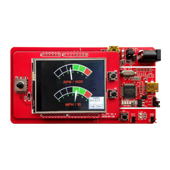
NuMaker-emWin-NUC126 OVERVIEW The NuMaker-emWin-NUC126 is an evaluation board for GUI application development on emWin library. The NuMaker-emWin- NUC126 consists of two parts: a NuMaker-PFM-NUC126 main board and a NuTFT extension board. The NuMaker-emWin-NUC126 is designed for emWin project evaluation, prototype development and validation. The NuMaker-PFM-NUC126 consists of two parts: an NUC126 target board and an on-board Nu-Link2- Me debugger and programmer. -
Page 7: Figure 1-2 Numaker-Pfm-Nuc126 Main Board
NuMaker-emWin-NUC126 Figure 1-2 NuMaker-PFM-NUC126 Main Board Figure 1-3 NuTFT Extension Board Apr, 26, 2021 Page 7 of 40 Rev 1.02... -
Page 8: Features
Arduino UNO Compatible Extension Connectors Supporting Resources For sample codes and introduction about emWin library, please refer to NUC126 BSP: https://www.nuvoton.com/resource-download.jsp?tp_GUID=SW1820210201134056 Visit NuForum for further discussion about the NuMaker-emWin-NUC126: http://forum.nuvoton.com/viewforum.php?f=31 Segger provides an emWin supporting forum. Questions regarding emWin usage are discussed at: https://forum.segger.com/index.php/Board/12-emWin-related/... -
Page 9: Numaker-Pfm-Nuc126 Main Board
NuMaker-emWin-NUC126 NUMAKER-PFM-NUC126 MAIN BOARD NuMaker-PFM-NUC126 Main Board Overview Figure 3-1 shows the main components and connectors of NuMaker-PFM-NUC126 main board. The following lists components and connectors: ➢ Nu-Link-Me V1.2 (ICE debugger): ⚫ ICE Controller NUC12SRE3DE (ICE_U2) ⚫ USB connector (ICEJ1) to PC Host ⚫... -
Page 10: Pin Assignment For Extended Connectors
NuMaker-emWin-NUC126 Pin Assignment for Extended Connectors The NuMaker-PFM-NUC126 main board is equipped with the target chip, NUC126VG4AE and extended connectors (JP7, JP8, JP9 and JP10) for LQFP100-pin. Figure 3-2 shows the NUC126VG4AE extended connectors. JP9 : Pin1 ~ Pin25 JP7 : Pin76 ~ Pin100 JP8 : Pin26 ~ Pin50 JP10 : Pin51 ~ Pin75 Figure 3-2 NuMaker-PFM- NUC126 Main Board Extended Connectors... -
Page 11: Table 3-1 Extended Connector Jp7 And Jp9 Interface With Nuc126Vg4Ae Gpio
NuMaker-emWin-NUC126 NUC126VG4AE NUC126VG4AE Header Header Pin No. Function Pin No Function PF.7 USB_VDD33_CAP PB.12 PB.0 PA.3 PB.1 PA.2 PB.2 PA.1 PB.3 PA.0 PB.4 PA.12 PB.8 PA.13 PB.9 PA.14 PB.10 PA.15 PB.11 PE.2 PB.13 PD.9 PB.14 PD.1 PB.15 PD.2 PB.5 PD.3 PB.6 PD.4 PB.7... -
Page 12: Table 3-2 Extended Connector Jp10 And Jp8 Interface With Nuc126Vg4Ae Gpio
NuMaker-emWin-NUC126 NUC126VG4AE NUC126VG4AE Header Header Pin No. Function Pin No Function PC.6 PC.7 PE.1 PE.4 PE.8 PE.5 PE.9 ICE_CLK PE.10 ICE_DAT PE.11 JP10 JP10 PA.8 PE.12 PA.9 PE.13 PA.7 DDIO PA.6 USB_VBUS PA.5 USB_D- PA.4 USB_D+ PD.10 PC.10 PD.11 PC.11 PD.12 PC.12 PD.13... -
Page 13: Arduino Uno Compatible Interface
NuMaker-emWin-NUC126 Arduino UNO Compatible Interface Figure 3-3 shows the Arduino UNO compatible interface. I2C1_SCL I2C1_DAT VREF VREF PE13 PE10 MCU_RESET MCU_RESET PE11 3VCC 3VCC PE12 5VCC 5VCC PC14 PC13 PC12 PB10 PC11 PB11 PC10 PB13 PB14 SPI1_SS RESET SPI1_CLK SPI1_MISO GPIO SPI1_MOSI Figure 3-3 Arduino UNO Compatible Interface... -
Page 14: Table 3-3 Arduino Uno Extension Connectors And Nuc126Vg4Ae Mapping Gpio List
NuMaker-emWin-NUC126 NuMaker-PFM-NUC126 NuMaker-PFM-NUC126 Header Header Compatible to Compatible to GPIO Pin of NUC126 GPIO Pin of NUC126 Arduino UNO Arduino UNO NU7.8 GPIO PB.12 NU7.4 SPI0_SS PD.12 NU7.7 NU7.3 RESET RESET NU7.6 SPI0_MOSI PD.13 NU7.2 SPI0_CLK PD.15 NU7.5 NU7.1 SPI0_MISO PD.14 NU3.1 PD.6... -
Page 15: System Configuration
NuMaker-emWin-NUC126 System Configuration 3.4.1 System Power Configure There are six pins in JP6 and two power modes can be selected. Mode 1: Using jumper to short VCC and ICE_VCC. USB5V ICE_VCC In mode 1, power source comes from J1 or CON2. User can plug the USB connector into J1 or CON2 to supply the power for NuMaker-PFM-NUC126 main board. -
Page 16: Power Source
NuMaker-emWin-NUC126 3.4.3 3.3V Power Source ⚫ J1 (ICE): (1) Short the VCC to ICE_VCC on JP6 (2) Short the ICE_VCC to 5VCC on JPR1. (3) Plug the USB connector into J1 to supply 5V power from PC host for NuMaker-PFM- NUC126 main board. -
Page 17: Nu-Link-Me
NuMaker-emWin-NUC126 Nu-Link-Me The NuMaker-PFM-NUC126 features a Nu-Link-Me ICE debugger and programmer. The Nu-Link-Me supports on-chip debugging and online ICP programming via SWD interface. It also supports drag-and- drop programming: programming the MCU by dragging the firmware image file into the Nu-Link-Me storage on PC. -
Page 18: Pcb Placement Of Numaker-Pfm-Nuc126 Main Board
NuMaker-emWin-NUC126 PCB Placement of NuMaker-PFM-NUC126 Main Board Figure 3-4 and Figure 3-5 show the front and rear view placement of NuMaker-PFM-NUC126 main board. Figure 3-4 NuMaker-PFM-NUC126 Main Board Placement - Front View Figure 3-5 NuMaker-PFM-NUC126 Main Board Placement - Rear View Apr, 26, 2021 Page 18 of 40 Rev 1.02... -
Page 19: Nutft Extension Board
NuMaker-emWin-NUC126 NUTFT EXTENSION BOARD NuTFT Extension Board Overview Figure 4-1 and Figure 4-2 show the main components and connectors of NuTFT extension board. The following lists components and connectors: ➢ Front View of NuTFT Extension Board: ⚫ Five-direction Joystick (J3) ⚫... -
Page 20: Figure 4-2 Rear View Of Nutft Extension Board
NuMaker-emWin-NUC126 ➢ Rear View of NuTFT Extension Board: ⚫ 16 Mbits (2 MB) SPI Flash * 1 (W25Q16CV) (U1) ⚫ Arduino Compatible Interface Connectors (NU1, NU2, NU5, NU6 and NU7) Arduino compatible interface connectors Arduino compatible SPI Flash interface connectors Arduino compatible interface connectors Figure 4-2 Rear View of NuTFT Extension Board... -
Page 21: Pin Assignment For Nutft Extension Board
NuMaker-emWin-NUC126 Pin Assignment for NuTFT Extension Board The pin arrangement of NuTFT is compatible with Arduino UNO. SPIFlash-CLK SPIFlash-MISO0 SPIFlash-MOSI0 3.3V SPIFlash-SS SPIFlash-MOSI1 SPIFlash-MISO1 LCM_LED Joystick-R ADC-YU Joystick-U ADC-XL Joystick-L ADC-YD Joystick-D ADC-XR Joystick-M Button-SW7 LCM_RESET Button-SW8 LCM_DC LCM_SPI_SS LCM_RESET LCM_SPI_CLK LCM_SPI_MISO LCM_SPI_MOSI... -
Page 22: Table 4-1 Arduino Uno Extension Connectors And Nutft Mapping Gpio List
NuMaker-emWin-NUC126 NuTFT NuTFT Header Header Compatible to Compatible to Pin of NuTFT Pin of NuTFT Arduino UNO Arduino UNO NU7.8 GPIO NU7.4 SPI0_SS SPI_SS NU7.7 NU7.3 RESET RESET NU7.6 SPI0_MOSI SPI_MOSI NU7.2 SPI0_CLK SPI_CLK NU7.5 NU7.1 SPI0_MISO SPI_MISO NU3.1 LCM_DC NU2.6 SW8 Push Button NU3.2... -
Page 23: System Configuration
NuMaker-emWin-NUC126 System Configuration 4.3.1 Arduino UNO Compatible Interface Connectors ⚫ NU1, NU2, NU5, NU6 and NU7: Arduino UNO compatible pins on the NuTFT extension board. 4.3.2 Push-Buttons ⚫ SW7: Push button controlled by A4, PB13 on NuMaker-PFM-NUC126 main board. ⚫ SW8: Push button controlled by A5, PB14 on NuMaker-PFM-NUC126 main board. -
Page 24: Pcb Placement Of Nutft Extension Board
NuMaker-emWin-NUC126 PCB Placement of NuTFT Extension Board Figure 4-4 and Figure 4-5 show the front and rear view placement of NuTFT extension board. Figure 4-4 NuTFT Extension Board Placement - Front View Figure 4-5 NuTFT Extension Board Placement - Back View Apr, 26, 2021 Page 24 of 40 Rev 1.02... -
Page 25: Numaker-Pfm-Nuc126 Main Board Schematics
NuMaker-emWin-NUC126 NUMAKER-PFM-NUC126 MAIN BOARD SCHEMATICS Nu-Link-Me Figure 5-1 shows the Nu-Link-Me circuit, which is a USB-to-SWD bridge used to program code to the target chip. Figure 5-1 Nu-Link-Me Circuit Apr, 26, 2021 Page 25 of 40 Rev 1.02... -
Page 26: Nuc126Vg4Ae Pin Assignment
NuMaker-emWin-NUC126 NUC126VG4AE Pin Assignment Figure 5-2 shows the pin assignment of the NUC126VG4AE. Figure 5-2 NUC126VG4AE Pin Assignment Apr, 26, 2021 Page 26 of 40 Rev 1.02... -
Page 27: Power Circuit
NuMaker-emWin-NUC126 Power Circuit Figure 5-3 shows power configurations of NuMaker-PFM-NUC126 main board. Figure 5-3 Power Circuit and Configurations Apr, 26, 2021 Page 27 of 40 Rev 1.02... -
Page 28: Arduino Uno Compatible Interface
NuMaker-emWin-NUC126 Arduino UNO Compatible Interface Figure 5-4 shows the Arduino UNO compatible interface of NU1 to NU5 connectors. Figure 5-4 Arduino UNO Compatible Interface Apr, 26, 2021 Page 28 of 40 Rev 1.02... -
Page 29: Reset Circuit
NuMaker-emWin-NUC126 Reset Circuit Figure 5-5 shows the reset circuit of the NUC126VG4AE. Figure 5-5 Reset Circuit Apr, 26, 2021 Page 29 of 40 Rev 1.02... -
Page 30: External Crystal Circuit
NuMaker-emWin-NUC126 External Crystal Circuit Figure 5-6 shows two external crystal circuits of the NUC126VG4AE. Figure 5-6 External Crystal Circuit Apr, 26, 2021 Page 30 of 40 Rev 1.02... -
Page 31: Led Circuit
NuMaker-emWin-NUC126 LED Circuit Figure 5-7 shows the power LED and IO_LED circuit of the NUC126VG4AE. The IO_LED is controlled by PC_9. Figure 5-7 Power LED and IO LED Circuit Apr, 26, 2021 Page 31 of 40 Rev 1.02... -
Page 32: Mcu I/O Connector
NuMaker-emWin-NUC126 MCU I/O Connector Figure 5-8 shows the MCU I/O connector circuit of the NuMaker-PFM-NUC126 main board. Figure 5-8 MCU I/O connector Circuit Apr, 26, 2021 Page 32 of 40 Rev 1.02... -
Page 33: Usb Port
NuMaker-emWin-NUC126 USB Port Figure 5-9 shows the USB circuit of the NuMaker-PFM-NUC126 main board. Figure 5-9 USB Circuit Apr, 26, 2021 Page 33 of 40 Rev 1.02... -
Page 34: Ice Interface Circuit
NuMaker-emWin-NUC126 ICE Interface Circuit Figure 5-10 shows the ICE interface circuit of the NuMaker-PFM-NUC126 main board. Figure 5-10 ICE Interface Circuit Apr, 26, 2021 Page 34 of 40 Rev 1.02... -
Page 35: Nutft Extension Board Schematics
NuMaker-emWin-NUC126 NUTFT EXTENSION BOARD SCHEMATICS Interface Connector Figure 6-1 shows the Interface connector circuit of NuTFT extension board. Figure 6-1 Interface Connector Circuit Apr, 26, 2021 Page 35 of 40 Rev 1.02... -
Page 36: Spi Flash Circuit
NuMaker-emWin-NUC126 SPI Flash Circuit Figure 6-2 shows the SPI Flash circuit of NuTFT extension board. Figure 6-2 SPI Flash circuit Apr, 26, 2021 Page 36 of 40 Rev 1.02... -
Page 37: Tft Lcd Circuit
NuMaker-emWin-NUC126 TFT LCD Circuit Figure 6-3 shows the TFT LCD circuit of NuTFT extension board. YU, XL, YD and XR are used for 4- wire ADC touch panel. Others are used for TFT LCD panel. Figure 6-3 TFT LCD Circuit Apr, 26, 2021 Page 37 of 40 Rev 1.02... -
Page 38: Button Circuit
NuMaker-emWin-NUC126 Button Circuit Figure 6-4 shows the Button circuit of NuTFT extension board. There are five-direction joystick and two push buttons. Figure 6-4 Button Circuit Apr, 26, 2021 Page 38 of 40 Rev 1.02... -
Page 39: Revision History
NuMaker-emWin-NUC126 REVISION HISTORY Date Revision Description 2018.07.26 1.00 Initial version Updated Figure 1-1. Added a note in section 2.4.2 about do not short 2018.08.15 1.01 the 5VCC to MCU when user uses the extension board. Changed the kit name from NuMaker-PFM- NUC126 Kit to NuMaker-emWin-NUC126. - Page 40 NuMaker-emWin-NUC126 Important Notice Nuvoton Products are neither intended nor warranted for usage in systems or equipment, any malfunction or failure of which may cause loss of human life, bodily injury or severe property damage. Such applications are deemed, “Insecure Usage”.
Need help?
Do you have a question about the NuMicro NUC126 Series and is the answer not in the manual?
Questions and answers