Sign In
Upload
Manuals
Brands
Nuvoton Manuals
Motherboard
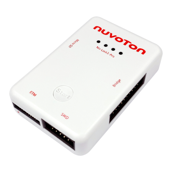
Nu-Link2-Pro
Nuvoton Nu-Link2-Pro Manuals
Manuals and User Guides for Nuvoton Nu-Link2-Pro. We have
1
Nuvoton Nu-Link2-Pro manual available for free PDF download: User Manual
Nuvoton Nu-Link2-Pro User Manual (77 pages)
Debugger and Programmer
Brand:
Nuvoton
| Category:
Motherboard
| Size: 6 MB
Table of Contents
Table of Contents
2
Introduction
8
Table 1.1-1 Nu-Link Debugger/ Programmer Technical Abbreviations
8
Nu-Link2-Pro Features
9
Getting Started with Nu-Link2-Pro
10
Nu-Link2-Pro Kit Contents
10
Figure 2.1-1 Nu-Link2-Pro Full Kit Contents
10
Nu-Link2-Pro PCBA
11
Figure 2.2-1 Front View of Nu-Link2-Pro PCBA
11
Figure 2.2-2 Rear View of Nu-Link2-Pro PCBA
11
Nu-Link2-Pro Overview
12
Figure 2.3-1 Nu-Link2-Pro Connector and Function Overview
12
Table 2.3-1 Status Leds Difference List
13
Connecting the Nu-Link2-Pro
14
Nu-Link2-Pro Compatible Extension Connectors
14
Figure 3.1-1 Pin Definition of Nu-Link2-Pro Connectors
14
SWD Interface Pin Definition and Function Connection
15
ICE Programming Connection
15
Table 3.2-1 SWD Interface Pin Definition and Description
15
Virtual COM Connection
16
Figure 3.2-1 SWD Interface Connection Diagram for ICE
16
Table 3.2-2 SWD Interface Corresponding Pin for ICE
16
Automatic IC Programming Connection
17
Figure 3.2-2 SWD Interface Connection Diagram for Virtual COM
17
Table 3.2-3 SWD Interface Corresponding Pin for Virtual COM
17
Figure 3.2-3 SWD Interface Connection Diagram for Automatic IC Programming
18
Table 3.2-4 SWD Interface Corresponding Pin for Automatic IC Programming
18
Bridge Interface Pin Definition and Function Connection
19
UART Connection
19
Table 3.3-1 Bridge Interface Pin Definition and Description
19
I 2 C Connection
20
Figure 3.3-1 Bridge Interface Connection Diagram for UART
20
Table 3.3-2 Bridge Interface Corresponding Pin for UART
20
Figure 3.3-2 Bridge Interface Connection Diagram for I 2 C
21
Table 3.3-3 Bridge Interface Pin for I 2 C
21
SPI Connection
22
Figure 3.3-3 Bridge Interface Connection Diagram for SPI
22
RS-485 Connection
23
Figure 3.3-4 Bridge Interface Connection Diagram for RS-485
23
Table 3.3-4 Bridge Interface Corresponding Pin for SPI
23
CAN BUS Connection
24
Figure 3.3-5 Bridge Interface Connection Diagram for CAN BUS
24
Table 3.3-5 Bridge Interface Corresponding Pin for RS-485
24
PWM and Capture
25
Figure 3.3-6 Bridge Interface Connection Diagram for PWM
25
Table 3.3-6 Bridge Interface Corresponding Pin for CAN BUS
25
ADC Connection
26
Figure 3.3-7 Bridge Interface Connection Diagram for ADC
26
Table 3.3-7 Bridge Interface Corresponding Pin for PWM
26
GPIO Connection
27
Figure 3.3-8 Bridge Interface Connection Diagram for GPIO
27
Table 3.3-8 Bridge Interface Corresponding Pin for ADC
27
Table 3.3-9 Bridge Interface Corresponding Pin for GPIO
28
ETM Interface Pin Definition and Function Connection
29
SWD Connection
29
Table 3.4-1 ETM Interface Pin Definition and Description
29
ETM Connection
30
ICP Offline Programming Function Connection
30
Figure 3.4-1 ETM Interface Connection Diagram for SWD and ETM Function
30
Figure 3.5-1 ICP Offline Programming Illustration of SWD Interface
31
Debugging and Programming
32
Debugging
32
Debug Mode
32
Breakpoints
32
System Viewer
32
Figure 4.1-1 Setting Breakpoints in Keil MDK Debug Mode
32
Figure 4.1-2 System Viewer Control Related Options in Keil MDK Debug Mode
33
Semihost
34
Figure 4.1-3 System Viewer in Keil MDK Debug Mode
34
Embedded Trace Macrocell (ETM)
35
Figure 4.1-4 Semihost Options in Keil MDK Debug Mode
35
Programming
36
ICP Online Programming
36
ICP Offline Programming
36
Figure 4.2-1 Online Programming Flow Diagram
36
ISP Online Programming
37
Software Serial Number (SN)
37
Figure 4.2-2 Offline Programming Flow Diagram
37
Wide Voltage Programming
38
Installing the Nu-Link2-Pro Driver
38
Figure 4.2-3 Software Serial Number (SN) Settings
38
Installation and Setup
39
Connecting to the Nu-Link2-Pro
39
Figure 5.1-1 Nu-Link2-Pro Connection Diagram
39
Software Setup
40
ICP Tool
40
Figure 5.2-1 Startup Screen of ICP Tool
40
Figure 5.2-2 ICP Tool Main Window
40
Figure 5.2-3 Select One Nu-Link2-Pro
41
Figure 5.2-4 ICP Tool Programming Options
41
Figure 5.2-5 Nu-Link2-Pro Connected with a Target Chip Detected
42
Figure 5.2-6 Nu-Link2-Pro Connected with no Target Chip Detected
42
Figure 5.2-7 Programming File Selection Window
43
Figure 5.2-8 Programming Completion Window
43
Keil MDK
44
Figure 5.2-9 Warning Message of "Device Not Found
44
Figure 5.2-10 Project File Migrate to Version 5 Format
44
Figure 5.2-11 Enable Debug Information for Keil MDK
45
Figure 5.2-12 Debugger Setting in Options Window
45
Figure 5.2-13 Programming Setting in Options Window
46
Figure 5.2-14 Nu-Link2-Pro Parameter Settings
46
Figure 5.2-15 Keil MDK Programmer Selection
47
Figure 5.2-16 Nu-Link2-Pro Programming Settings
47
Table 5.2-1 Debugger Function Settings Description
47
Figure 5.2-17 Compile and Download the Project
48
Figure 5.2-18 Keil MDK Debug Mode
48
Figure 5.2-19 Debug Message on Serial Port Terminal Windows
49
Figure 5.2-20 Open M480 Project
49
Figure 5.2-21 Trace Setup with ETM
50
Figure 5.2-22 Initialize File for Trace Pins
50
Figure 5.2-23 Build and Download Windows for ETM
51
Figure 5.2-24 Tracing Information Dialog
51
Figure 5.2-25 Breakpoint Setting and Execution
52
Iar Ewarm
53
Figure 5.2-26 Options Selection
53
Figure 5.2-27 IAR EWARM Target Chip Selection
53
Figure 5.2-28 Set IAR EWARM as Third-Party Driver for Debugger & Programmer
54
Figure 5.2-29 IAR EWARM Programming Settings
54
Figure 5.2-30 Select.board File for IAR EWARM
55
Figure 5.2-31 Set the Path of the IAR EWARM Debugger Driver Plugin
55
Figure 5.2-32 Specify the Port and Target I/O Voltage
56
Figure 5.2-33 Compile and Download the Project
56
Figure 5.2-34 IAR EWARM Debug Mode
57
Figure 5.2-35 Debug Message on Serial Port Terminal Windows
57
Nueclipse GCC
58
Figure 5.2-36 Import the Project in Nueclipse
58
Figure 5.2-37 Import Projects Windows
58
Figure 5.2-38 Open Project Properties Window
59
Figure 5.2-39 Project Properties Settings
59
Figure 5.2-40 Build Project
60
Figure 5.2-41 Open Debug Configuration
61
Figure 5.2-42 Main Tab Configuration
61
Figure 5.2-43 Debugger Tab Configuration
62
Figure 5.2-44 Debugger Tab Configuration
63
Figure 5.2-45 Nueclipse Debug Mode
64
Figure 5.2-46 Debug Message on Serial Port Terminal Windows
64
ISP Tool
65
Figure 5.2-47 Startup Screen of ISP Tool
65
Figure 5.2-48 ISP Is Not Connected to any Device of ISP Tool
65
Figure 5.2-49 ISP Firmware Sample Code Project
66
Table 5.2-2 Connection Interface Option of ISP Tool
66
Figure 5.2-50 Boot from LDROM Setting in Keil ISP Firmware Project
67
Figure 5.2-51 Connect to Target Chip with SPI Interface
67
Figure 5.2-52 Select VCOM Port Number with UART Interface
68
Table 5.2-3 Entering the ISP Conditions for ISP Tool Connection
68
More Features of Nu-Link2-Pro Firmware
69
Figure 5.2-53 Program Data to Target Chip with SPI Interface
69
Figure 5.2-54 Update Nu-Link2 Firmware or DUT Firmware
70
Appendix
71
Nu-Link2-Pro Operating Current of ICP
71
Table 6.1-1 Nu-Link2-Pro Operating Current (Online Programming)
71
Table 6.1-2 Nu-Link2-Pro Operating Current (Offline Programming) of SPI Flash
71
Table 6.1-3 Nu-Link2-Pro Operating Current (Offline Programming) of USB Flash
71
Table 6.1-4 Nu-Link2-Pro Operating Current (Offline Programming) of Micro SD Card
71
Nu-Link2-Pro Operating Current of ISP
72
Table 6.2-1 Operating Current of ISP Online Programming
72
Automatic IC Programming System
73
Operation Sequence and Waveform
73
Figure 6.3-1 SWD Connector Pin Diagrams
73
Figure 6.3-2 PASS Waveform
73
Figure 6.3-3 FAIL Waveform
74
Nu-Link Debugger and Programmer Comparison
75
Table 6.1-1 Comparison of All Nu-Link Debugger and Programmer
75
Table 6.1-2 Comparison of Integrated Nu-Link Debugger and Programmer on Development Board
76
Revision History
77
Advertisement
Advertisement
Related Products
Nuvoton NuMicro NuTiny-SDK-NUC505
Nuvoton NuTiny-SDK-120
Nuvoton NuMicro NuMaker-IoT-M487
Nuvoton NuMicro NuMaker UNO
Nuvoton NUC900 Series
Nuvoton NuMaker-M251SD
Nuvoton NuMaker NUC980
Nuvoton NuMicro NuMaker-M467HJ
Nuvoton NuMicro NuMaker-IoT-M467
Nuvoton NuMicro NuMaker-IIoT-NUC980G2D
Nuvoton Categories
Motherboard
Microcontrollers
Computer Hardware
Amplifier
Control Unit
More Nuvoton Manuals
Login
Sign In
OR
Sign in with Facebook
Sign in with Google
Upload manual
Upload from disk
Upload from URL