Advertisement
OPERATOR'S MANUAL
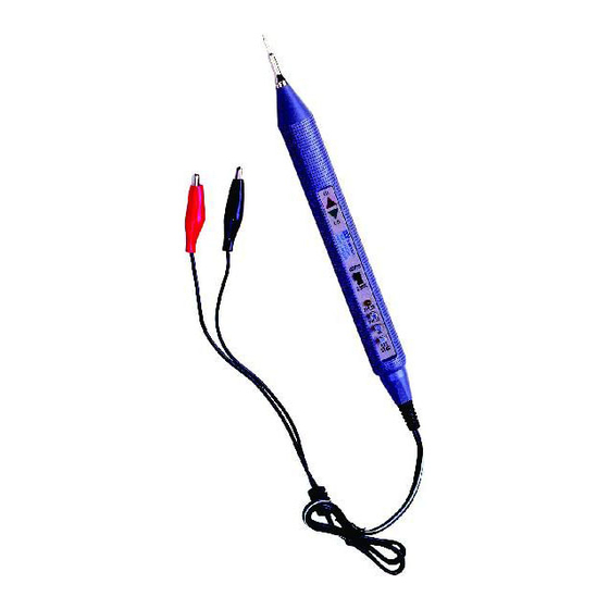
MODEL GLP-1 A
LOGIC PROBE (50MHz FREQUENCY DISPLAYABLE) & LOGIC PULSER
MODEL GPG-2A
LOGIC PULSER
INTRODUC,:'ION
The Logic Probe ideal for troubleshooting and analysis of logic circuits. It works as a level detector,
a pulse detector and a pulse stretcher.
It features include: a. Circuit powered.
c. Logic HI; LO; PULSER
a. Attach red alligator clip to positive side of d.c. power supply of printed circuit board under test.
b. Attach black alligator clip to negative side of d.c. power supply of printed circuit board under
test.
c. LED Display Pattern:
INPUT SIGNAL
Logic "1"
Logic "O"
Bad Level or Open Circuit
Square Wave < 200KHz
Square Wave > 200KHz
Narrow High Pulse
Narrow Low Pulse
GENERAL:
Operating Temperature .............................................. 0
Storage Temperature ................................................ -20
................................................................. GLP-1 A 1. 76 Ounces (50g) approx.
Weight
Dimensions .............................................................. 8.2 Inches (21 cm) Long X .
ELECTRICAL (At 23 ± 5
Maximum Input Signal Frequency ................................ 50MHz
Input Impedance ....................................................... 120K Q
Operating Supply Range ............................................ 4V DC Minimum, 1 BV DC Maximum
TTL:
Logic "1" (HI LED) ........................................ > 3.0V ± 0.25V
Logic "O" (LO LED) ....................................... <0.75V ± 0.25V
LOGIC PROBE (GLP-1A)
b. LED indicators: HI (red LED), LO (green LED)
LED
HI
•
I
0
0
•
•
•
•
°
C, 75% Relative Humidity Maximum):
Visit us at www.TestEquipmentDepot.com
•LED ON
LO
* Blinking LED, Intensity is proportional
0
to the duty cycle of the signal ob
•
served.
Note: If model GLP-1A LO (green LED)
0
•
lighted, when power supply voltage
is 7-18 Vee. This is normal condition
•
and will not effect the logic probe
•
features.
•
°
C to 50
°
C, 80% Relative Humidity.
°
C to 65
°
GPG-2A 1 .4 Ounces (40g) approx.
0.7 Inches (1.8cm) Wide X.
0.7 Inches (1.8cm) Deep.
99 Washington Street
Melrose, MA 02176
Phone 781-665-1400
Toll Free 1-800-517-8431
0 LED OFF
C, 75% Relative Humidity.
Advertisement
Table of Contents

Related Manuals for GW Instek GLP-1A


Summary of Contents for GW Instek GLP-1A
- Page 1 * Blinking LED, Intensity is proportional Logic "1" to the duty cycle of the signal ob • served. Logic "O" Note: If model GLP-1A LO (green LED) Bad Level or Open Circuit • • lighted, when power supply voltage Square Wave < 200KHz is 7-18 Vee.
- Page 2 Power Supply Protection ..•........± 20V DC When supply voltage rs 7-18 Vee Green LED may be light. This is normal condition. LOGIC PULSER (GLP-1A,GPG-2A) INTRODUCTION The Logic Pulser is a very effective tool for inspecting and repairing the logic circuit. It can be used directly to inject a signal into the logic circuits without removing the IC or breaking the circuits.
Need help?
Do you have a question about the GLP-1A and is the answer not in the manual?
Questions and answers