Nordson Auto-Flo II Customer Product Manual
Manual dispensers
Hide thumbs
Also See for Auto-Flo II:
- Product manual (44 pages) ,
- Customer product manual (34 pages) ,
- Instruction sheet (10 pages)
Table of Contents
Advertisement
Quick Links
t
Auto-Flo
II
Manual Dispensers
Customer Product Manual
Part 1614433−01
Issued 9/19
For parts and technical support, call the
Finishing Customer Support Center at (800) 433-9319.
This document is subject to change without notice.
Check http://emanuals.nordson.com/finishing for the latest version.
NORDSON CORPORATION • AMHERST, OHIO • USA
Advertisement
Table of Contents

Related Manuals for Nordson Auto-Flo II


Summary of Contents for Nordson Auto-Flo II
- Page 1 Customer Product Manual Part 1614433−01 Issued 9/19 For parts and technical support, call the Finishing Customer Support Center at (800) 433-9319. This document is subject to change without notice. Check http://emanuals.nordson.com/finishing for the latest version. NORDSON CORPORATION • AMHERST, OHIO • USA...
-
Page 2: Table Of Contents
... . . Contact Us Notice This is a Nordson Corporation publication which is protected by copyright. Nordson Corporation welcomes requests for information, comments, and Original copyright date 2019. No part of this document may be inquiries about its products. - Page 3 Change Record Change Record Revision Date Change 9/19 Released Part 1614433- 01 E 2019 Nordson Corporation...
- Page 4 Change Record Part 1614433- 01 E 2019 Nordson Corporation...
-
Page 5: Safety
While operating manual spray guns, make sure you are grounded. Wear electrically conductive gloves or Use of Nordson equipment in ways other than those a grounding strap connected to the gun handle or described in the documentation supplied with the other true earth ground. -
Page 6: High-Pressure Fluids
Consultation with a plastic surgeon or a reconstructive hand surgeon may be advisable. Use only replacement parts that are designed for use with original equipment. Contact your Nordson The seriousness of the wound depends on where the representative for parts information and advice. -
Page 7: Halogenated Hydrocarbon Solvent Hazards
“Bromo-” Iodine “Iodo-” Check your material SDS or contact your material supplier for more information. If you must use halogenated hydrocarbon solvents, contact your Nordson representative for information about compatible Nordson components. Action in the Event of a Malfunction If a system or any equipment in a system malfunctions,... -
Page 8: Description
Auto-Flo II Manual Dispensers Description See Figure 2. The Auto−Flo Zero Cavity manual NOTE: Throughout the remainder of this manual dispenser is used in a variety of applications to the Auto−Flo Zero Cavity manual dispenser is dispense adhesives, sealants, and other materials. -
Page 9: Theory Of Operation
Auto-Flo II Manual Dispensers Specifications Theory of Operation See Figure 3. Pulling the trigger supplies air to the valve−open air inlet (5). The piston is pushed Item upward, pulling the piston stem (4) off the seat (3). Material flows into the material inlet (2) and out of... -
Page 10: Installation
Auto-Flo II Manual Dispensers Installation Select a Nozzle WARNING: Allow only qualified personnel to perform the following tasks. Follow the Nozzle selection depends on the type of material safety instructions in this document and all being dispensed, the desired bead size, and the other related documentation. -
Page 11: Operation
Auto-Flo II Manual Dispensers Operation How to Clear a Blocked Nozzle WARNING: Allow only qualified personnel to perform the following tasks. Follow the 1. Shut off air pressure to the material unloader. safety instructions in this document and all other related documentation. -
Page 12: Maintenance
If you cannot safety instructions in this document and all solve the problem with the information given here, other related documentation. contact your local Nordson representative for help. Problem Possible Cause Corrective Action Dirty or damaged metal sealing Clean the nozzle if dirty. -
Page 13: Repair
Auto-Flo II Manual Dispensers Repair WARNING: Allow only qualified personnel to perform the following tasks. Follow the safety instructions in this document and all other related documentation. System or material pressurized. Relieve pressure. Failure to observe this warning may result in serious injury or death. -
Page 14: Parts
Auto-Flo II Manual Dispensers Parts To order parts, call the Nordson Industrial Coating Systems Customer Support Center at (800) 433−9319 or contact a local Nordson representative. Zero Cavity 0.090-Inch Diameter Tip Dispensers See Figure 6 and the following parts list. - Page 15 S SCREW, button, socket, 6−32 x 0.375, stainless steel, Grade 8 per ISO 7380 NOTE A: The fluid fitting is application specific and is not included with the dispenser. B: Refer to manual 1103506, Auto-Flo II Zero Cavity Dispense Valves to order parts. AR: As Required Part 1614433−01...
-
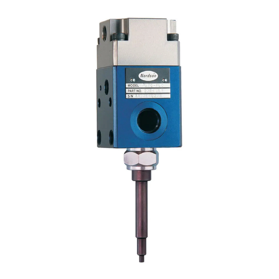
Page 16: Zero Cavity 0.090-Inch And 3-Mm Diameter Tip With Pressure Switch Dispensers
Auto-Flo II Manual Dispensers Zero Cavity 0.090-Inch and 3-mm Diameter Tip with Pressure Switch Dispensers See Figure 7 and refer to the following parts list. MODEL No: MODEL No: PART No: PART No: SERIAL No: SERIAL No: ZERO CAVITY 3‐MM DIAMETER TIP ZERO CAVITY 0.090‐IN. - Page 17 Auto-Flo II Manual Dispensers Item Part Part Description Quantity Note — 1108489 DISPENSER, Auto-Flo, 3-mm diameter tip, zero cavity with pressure switch DISPENSER, Auto-Flo, 0.090-in. diameter tip, zero cavity — 1612969 with pressure switch 972623 972623 S FITTING, barb, elbow, ¼ T x ⅛...
- Page 18 234867 S BODY, valve, air, FP−200 NOTE A: Dispenser 1108489 uses 5 elbow fittings. Dispenser 1612969 uses 3 elbow fittings. B: Refer to manual 1103506, Auto-Flo II Zero Cavity Dispense Valves to order parts. AR: As Required NS: Not Shown Sensor Kit The following kit is available for the dispensers.
Need help?
Do you have a question about the Auto-Flo II and is the answer not in the manual?
Questions and answers