Advertisement
Quick Links
Warranty:
BYOC, LLC guarantees that your kit will be complete and that all parts and
components will arrive as described, functioning and free of defect. Soldering,
clipping, cutting, stripping, or using any of the components in any way voids this
guarantee. BYOC, LLC guarantees that the instructions for your kit will be free of
any major errors that would cause you to permanently damage any components
in your kit, but does not guarantee that the instructions will be free of typos or
minor errors. BYOC, LLC does not warranty the completed pedal as a whole
functioning unit nor do we warranty any of the individual parts once they have
been used. If you have a component that is used, but feel it was defective prior to
you using it, we reserve the right to determine whether or not the component was
faulty upon arrival. Please direct all warranty issues to:
sales@buildyourownclone.com This would include any missing parts issues.
Return:
BYOC, LLC accepts returns and exchanges on all products for any reason, as long as
they are unused. We do not accept partial kit returns. Returns and exchanges are for the
full purchase price less the cost of shipping and/or any promotional pricing. Return
shipping is the customer's responsibility. This responsibility not only includes the cost
of shipping, but accountability of deliver as well. Please contact
sales@buildyourownclone.com to receive a return authorization before mailing.
Build Your Own Clone
Phase Royal
Kit Instructions
Advertisement

Related Manuals for BYOC Phase Royal


Summary of Contents for BYOC Phase Royal
- Page 1 Return: BYOC, LLC accepts returns and exchanges on all products for any reason, as long as they are unused. We do not accept partial kit returns. Returns and exchanges are for the full purchase price less the cost of shipping and/or any promotional pricing. Return shipping is the customer’s responsibility.
- Page 2 That being said, we will do our best to help you as much as we can. Our philosophy at BYOC is that we will help you only as much as you are willing to help yourself. We have a wonderful and friendly DIY discussion forum with an entire section devoted to the technical support and modifications of BYOC kits.
-
Page 3: Table Of Contents
PHASE ROYAL INSTRUCTION INDEX Before You Get Started..........page 4 - 6 Parts Checklist……………………....……..page 7 - 8 Populating the Circuit Board…………....page 9 - 21 ... -
Page 4: Before You Get Started
Before you get started.. There are a two things about this particular build that you should be aware of so that you don't get confused when you compare the parts list to the layout on the PCB. - Page 5 ...
- Page 6 This is a picture of the top side of the completed PCB assembly to be used as a reference throughout the build. NOTE: There is a footswitch socket between eyelets “5” and “4” that is not part of the standard kit.
-
Page 7: Parts Checklist
Parts Checklist for BYOC Phase Royal Resistors: 2 - 4k7 (yellow/purple/black/brown/brown) 15 - 10k (brown/black/black/red/brown) 10 - 22k (red/red/black/red/brown) 2 - 56k (green/blue/black/red/brown) 4 - 150k (brown/green/black/orange/brown) 3 - 470k (yellow/purple/black/orange/brown) 1 - 1M (brown/black/black/yellow/brown) 1 - 2.2M (red/red/black/yellow/brown ... - Page 8 Hardware: 1 - drilled enclosure w/ 4 screws 1 - byoc phase royalPCB 1 - SPDT toggle switch 1 - 3PDT footswitch 4 - knobs 1 - AC adaptor jack 1 - ¼”mono jack 1 - ¼”stereo jack...
-
Page 9: Populating The Circuit Board
Populating the Circuit Board STEP 1: Add the resistors. Resistors are not polarized, so it does not matter which end goes in which solder pad. Do not add the 2.2M (2M2) resistor yet. - Page 10 Step 2: Add the diodes. Be sure to match the end of the diode wit the stripes to the layout on the PCB. The striped end should go in the square solder pad. The Black Silicon 1n4001 diode goes in the space with no markings. The orange glass 1n4733 5.1v Zener diode goes in the spot marked ‘5.1v’.
- Page 11 Step 3: Add the 2.2M (2M2) resistor. Stand it on end. Insert one end into one of the eyelets highlighted in red. Bend the other end and insert it into the other eyelet highlighted in red. See pictures below for examples.
- Page 13 STEP 4: Add the 8 pin IC sockets. ONLY SOLDER THE SOCKET! NOT THE ACTUAL IC! These are sockets. The sockets get soldered to the PCB. The ICs get inserted into the sockets. The actual IC chips themselves, never get soldered. You will insert the ICs into the sockets after the entire pedal has been built.
- Page 14 STEP 5: Add the film and ceramic capacitors. These capacitors are non- polarized, so you can insert them into the PCB either way. The capacitor highlighted in pink is the ceramic disc.
- Page 15 Step 6: Add the Transistors. The six 2N5952 JFETs go in the spots highlighted in red. The 2N5087 goes in the spot highlighted in pink. Be sure to orient the transistors so that the flat side of the transistor body matches up with the flat side on the PCB layout.
- Page 16 Step 7: Add the 250k trimpot. Note that the PCB has 5 holes, but the actual trimpot itself will only have 3 leads. This is so that the PCB can accommodate a variety of different makes and model of trimpots. There should only be one way in which the trim pot provided with your kit fits easily into the PCB.
- Page 17 ADJUSTING THE TRIMPOT: Once you have completed your build(not before), you will need to adjust the trimpot before the phaser will actually work. There is no specific voltage that you should try to set it for. Simply use your ears! You are setting it so that the phaser has the fullest sweep that sounds as close to the way you want it to sound.
- Page 18 STEP 8: Add the aluminum electrolytic capacitors. These are polarized. The positive end will have a longer lead and should go in the square solder pad. The negative end will have a shorter lead with a black strip running down the body of the capacitor.
- Page 19 Step 9: Add the remaining IC socket to the bottom solder side of the PCB. Be sure to orient the socket so that the notch matches the outline in the diagram above.
-
Page 20: Main Pcb Assembly
Main PCB Assembly Step 1: Mount the AC adapter jack to the enclosure. Your kit may come with either an external thread or internal thread. Don’t get confused by this. They still function exactly the same. You just thread the external nut on the outside and the internal nut on the inside. - Page 21 Step 2: Flip the PCB over so that the bottom or solder side is up. Insert the four potentiometers, one switch, and the LED into the bottom side of the PCB. DO NOT SOLDER ANYTHING YET!!! The LED will have one lead that is longer than the other. THIS WILL GO INTO THE SQUARE SOLDER HOLE.
- Page 22 Step 3: Hold the PCB in one hand so that the component side of the PCB is in the palm of your hand and the bottom side with the pots, toggle switch and LED is facing up. Now use your other hand to guide the predrilled enclosure onto the PCB assembly so that the pots, toggle switch and LED all go into their respective holes.
-
Page 23: Wiring
WIRING Step 6: Connect the TIP (negative) terminal of the DC adapter jack to the eyelet on the PCB labeled “-“. Connect the SLEEVE of the DC adapter jack to the eyelet on the PCB labeled “+” farthest to the right. Connect the battery disconnect terminal of the DC adapter jack to the second eyelet on the PCB labeled “+”... - Page 24 Stereo (input) Jack Mono (output) Jack Step 1: Install the 1/4” jacks to the enclosure.
- Page 25 Step 2: Install the footswitch. Orient the footswitch so that the flat sides of the solder lugs are like the diagram below. NOTE: There are no actual number markings on the footswitch. There are two correct ways you can orient the footswitch. They are both 180 degrees of each other.
- Page 26 FOOT SWITCH SOLDER LUG DESIGNATIONS Step 3: Wiring the foot switch. Make a jumper between lugs 3 & 6 from clippings from the resistors. • Simply use your needle nose pliers to bend a piece of clipping into a U shape &...
- Page 27 Cut a two 2” piece of wire. Strip 1/8” off each end and tin. • Strip ¾” off the other end and very carefully tin. You do not want too • much solder on this end. Thread the longer stripped end into LUG4 and through to LUG9. •...
- Page 28 Step 5: Connect the wires at the top end of the PCB to the IN and OUT jacks. The “out” eyelet will go to the tip of the OUT jack and the “in” eyelet will go to the tip of the IN jack (refer to page 22). Connect the ground eyelet on the left to the sleeve of the IN.
- Page 29 Installing IC/Finish up Don't forget to add the knobs, put the cover on the enclosure, and apply the bumpers to the cover. Don't forget to adjust your trimpot. Then put the cover on the enclosure and apply the bumpers to the cover is you like to use them. ...
-
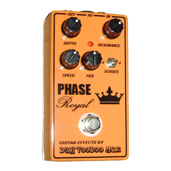
Page 30: Operation Overview
Operating Overview DEPTH: Sometimes called Width or Intensity. Controls intensity of the actual phase shifting. MIX: Sometimes called Ratio or Blend. Controls the mix of dry & phase shifted signal. Clockwise = more clean signal. Counter Clockwise = more phase shifting SPEED: Sometimes called Rate or Frequency. - Page 31 DC power supply - Use a 2.5mm negative tip 9VDC adaptor (this is your standard guitar fx style adaptor). If using battery power, only use a single 9V battery. Current Draw - 5.5mA Input Impedance - 470k ohms ...
- Page 32 ...
- Page 33 Please visit http://byocelectronics.com/board for any technical support ...
Need help?
Do you have a question about the Phase Royal and is the answer not in the manual?
Questions and answers