Advertisement
Quick Links
Build Your Own Clone
Phase Royal
Kit Instructions
Warranty:
BYOC, Inc. guarantees that your kit will be complete and that all parts and components
will arrive as described, functioning and free of defect. Soldering, clipping, cutting,
stripping, or using any of the components in any way voids this guarantee. BYOC, INC
guarantees that the instructions for your kit will be free of any majors errors that would
cause you to permanently damage any components in your kit, but does not guarantee
that the instructions will be free of typos or minor errors. BYOC, INC does not
warranty the completed pedal as a whole functioning unit, nor do we warranty any of the
individual parts once they have been used. If you have a component that is used, but feel
it was defective prior to you using it, we reserve the right to determine whether or not the
component was faulty upon arrival. Please direct all warranty issues to:
sales@buildyourownclone.com This would include any missing parts issues.
Return:
BYOC, Inc. accepts returns and exchanges on all products for any reason, as long as they
are unused. We do not accept partial kit returns. Returns and exchanges are for the full
purchase price less the cost of shipping and/or any promotional pricing. Return shipping
is the customer's responsibility. This responsibility not only includes the cost of
shipping, but accountability of deliver as well. Please contact
sales@buildyourownclone.com to receive a return authorization before mailing.
Tech Support:
BYOC, Inc. makes no promises or guarantees that you will successfully complete your
kit in a satisfactory manor. Nor does BYOC, Inc. promise or guarantee that you will
receive any technical support. Purchasing a product from BYOC, Inc. does not entitle
1
Advertisement

Related Manuals for BYOC Phase Royal


Summary of Contents for BYOC Phase Royal
- Page 1 This would include any missing parts issues. Return: BYOC, Inc. accepts returns and exchanges on all products for any reason, as long as they are unused. We do not accept partial kit returns. Returns and exchanges are for the full purchase price less the cost of shipping and/or any promotional pricing.
- Page 2 That being said, we will do our best to help you as much as we can. Our philosophy at BYOC is that we will help you only as much as you are willing to help yourself. We have a wonderful and friendly DIY discussion forum with an entire section devoted to the technical support and modifications of BYOC kits.
-
Page 3: Table Of Contents
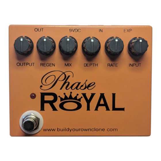
Phase Royal Kit Instruction Index Parts Checklist………………………....…..page 5 Populating the Circuit Board……....…...…..page 7 Main PCB Assembly..........page 20 Wiring………………………………......page 25 Operation Overview...........page 27 Schematic..............page 28... - Page 4 This is what your kit should look like when it’s complete. Your kit may come with different color capacitors, switches ect. Don’t be alarmed by this. They all still do the exact same thing.
-
Page 5: Parts Checklist
Parts Checklist for the Phase Royal Kit Resistors: (Metal Film (5 Bands) / Carbon Film (4 Bands)) 2 - 22R (Red/Red/Black/Gold/Brown) / (Red/Red/Brown/Gold) 1 - 220R (Red/Red/Black/Black/Brown) / (Red/Red/Brown/Gold) 2 - 470R (Yellow/Purple/Black/Black/Brown) / (Yellow/Purple/Brown/Gold) 2 - 4k7 (Yellow/Purple/Black/Brown/Brown) / (Yellow/Purple/Red/Gold... - Page 6 2 - B100k (INPUT LEVEL, DEPTH) 1 - C100k (REGEN) Hardware: 1 - predrilled enclosure w/ 4 screws 1 - Phase Royal Printed Circuit Board 1 - 3PDT Footswitch 4 - 1X4 Header socket 2 - Enclosed Jacks 1 - Switching Jack...
-
Page 7: Populating The Circuit Board
Populating the Circuit Board Step 1: Add all the resistors. Resistors are not polarized and can be inserted into the PCB in either direction, meaning you don’t have to worry about orienting them. - Page 8 Step 2: Add the header sockets.
- Page 9 Add the diode. Be sure to match the end of the diode with the stripe to Step 3: the layout on the PCB. The striped end should go in the square solder pad.
- Page 10 Step 4: Add the IC sockets. Be sure to align the notch on the IC sockets with the notch on the PCB screenprint. For the TL072 ICs highlighted in red that say ‘on back’, place the sockets on the back of the PCB. This is required to allow the module board to sit in the headers properly.
- Page 11 Step 6: Add the optocoupler. Be sure to orient it correctly, and mount it on the underside of the PCB. The longer lead will go into the square hole. There will also be a painted stripe on the body of the optocoupler to indicate the LED Anode, which goes into the square hole.
- Page 12 NOTE ABOUT THE OPTOCOUPLER The optocoupler is a combination of a LED (Light Emitting Diode) and LDR (Light Dependent Resistor) sealed into shrink-wrap. The legs might be a little vague, but if you know what to look for, it’s easy to figure out. The LED side will have two different lengths for the legs, with the long leg being the ANODE, or positive end, and the shorter leg being the CATHODE, or negative end.
- Page 13 Step 7: Add the transistors. Be sure to match the flat side of the transistors with the flat side on PCB layout. Allow enough room between the PCB and transistor bodies to lay them flat against the screenprinted area. The transistor highlighted in RED is the 2N3904.
- Page 14 Step 8: Add the film and ceramic disc capacitors. These are non-polarized so they can go in either direction. The ceramic disc capacitors are highlighted in yellow and are also non-polarized.
- Page 15 Step 9: Add the aluminum electrolytic capacitors. These ARE polarized, meaning there is a positive and negative end. The positive side will have a longer lead and goes in the square solder pad. The negative side will have a shorter lead and a stripe running along the body of the cap, and goes in the round solder pad.
- Page 16 Step 10: Add the trimpots. There are 5 holes, but only three legs on the trimpots. This is normal. Your trimpot will only fit into three holes; the additional holes are to accommodate various sizes of trimpots. NOTE: The ‘UPPER LIMIT’ trimpots are both 250k, and the ‘LOWER LIMIT’...
- Page 17 NOTE: There is no battery snap option available for the pedal. The circuit draws too much current for a battery to be used.
- Page 18 At this point, your build will look like this: Front...
- Page 19 Back...
-
Page 20: Main Pcb Assembly
Main PCB Assembly Step 1: Flip the PCB over so that the bottom or solder side is up. Insert the potentiometers and the LED into the bottom side of the PCB. If your pots have covers, remove them before continuing. You might have to cut a slit in the cover with a blade and use a small screwdriver to get leverage DO NOT SOLDER ANYTHING YET!!! (See below for advanced tip) - Page 21 Remember to install the opamps before the next step! Step 2: Hold the PCB in one hand so that the component side of the PCB is in the palm of your hand and the bottom side with the pots, toggle switch and LED is facing up.
- Page 22 You will want to place the jacks into the enclosure so the sleeve terminal is facing the right like the picture above. Be sure to remember the lock washers so the jacks don’t spin on their own. Install the switching jack in the enclosure with the lugs facing up, or towards the back plate of the enclosure.
- Page 23 Step 5: Install the footswitch. Orient the footswitch so that the flat sides of the solder lugs are like the diagram below. NOTE: There are no actual number markings on the footswitch. There are two correct ways you can orient the footswitch. They are both 180 degrees of each other.
- Page 24 FOOT SWITCH SOLDER LUG DESIGNATIONS Step 5a: Make a jumper between lugs 3 & 6 from clippings from the resistors. Simply use your needle nose pliers to make a U shape & insert into lugs 3 & 6, then solder. Step 5b: Connect a wire to LUG 4 that also jumpers to LUG9.
-
Page 25: Wiring
WIRING Step 6: Connect the TIP (negative) terminal of the DC adapter jack to the eyelet on the PCB labeled “-“. Connect the SLEEVE of the DC adapter jack to the eyelet on the PCB labeled “+” farthest to the right. The BATTERY lug is not connected. - Page 26 Finished Wiring for Main board NOTE: There is no battery snap, therefore you can leave the middle lug of the DC Jack unconnected. Setting the trimpots: When you are done with your build, and ready to use the pedal, you will use these to control the slowest and fastest speeds. Use your ear and your personal preference.
-
Page 27: Operation Overview
Operating Overview OUTPUT: Controls the overall output level. REGEN: Controls the amount of feedback in the phase circuit. MIX: Blends between the dry and wet signals -- CW = fully wet, CCW = Fully dry. DEPTH: Controls the rise and fall depth of the LFO. RATE: controls the speed of the LFO signal. - Page 29 For hi-res schematic visit: http://byocelectronics.com/phaseroyalschematic.pdf Please visit http://byocelectronics.com/board For any technical support Copyright 2018 BYOC, Inc.
Need help?
Do you have a question about the Phase Royal and is the answer not in the manual?
Questions and answers