Advertisement
Quick Links
Advertisement

Related Manuals for BYOC Super 8


Summary of Contents for BYOC Super 8
- Page 1 Build Your Own Clone Super 8 Kit Instructions...
- Page 2 That being said, we will do our best to help you as much as we can. Our philosophy at BYOC is that we will help you only as much as you are willing to help yourself. We have a wonderful and friendly DIY discussion forum with an entire section devoted to the technical support and modifications of BYOC kits.
- Page 3 When posting a tech support thread on the BYOC forum, please post it in the correct lounge, and please title your thread appropriately. If everyone titles their threads “HELP!” then it makes it impossible for the people who are helping you to keep track of your progress.
- Page 4 Super 8 Instruction Index Parts Checklist………………………....…..page 6 Populating and Wiring the Circuit Board..…..page 8 Operation Overview...........page 27 Schematic..............page 31...
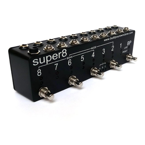
- Page 5 Study this for a few minutes before you begin. This is what your kit should look like when it’s complete. If you come to a step that is confusing, come back to this picture and take a look. It may help. Your kit may come with different color capacitors, switches, relays, etc.
-
Page 6: Parts Checklist
Parts Checklist for Super 8 Kit Resistors: 23 – 470 (Yellow/Purple/Black/Black/Brown) 6 - 10k (Brown/Black/Black/Red/Brown) 3 - 100k (Brown/Black/Black/Orange/Brown) 1 – 1M (Brown/Black/Black/Yellow/Brown) Visit www.byocelectronics.com/resistorcodes.pdf for more information on how to differentiate resistors. Capacitors: 1 - .01uF or 10n film cap (may say “103” on the body) 1 - .1uF or 100n film cap (may say “104”... - Page 7 1 - AC adaptor jack 10 - ¼”stereo PC mount jack 9 - ¼” enclosed stereo or mono panel mounted jack 9 - Red LED 9 – Green LED 3 – Yellow LED 4 – rubber bumpers hook-up wire...
-
Page 8: Populating And Wiring The Circuit Board
Populating and Wiring the Circuit Board Step 1: Add all the resistors. Resistors are not polarized and can be inserted in either direction. - Page 9 Add the 4.3v zener diode. The striped end of the diode will go into the square hole. Step 2:...
- Page 10 Add the IC sockets. The sockets will have one end that has a notch in it. Be sure to orient the sockets so Step 3: that the side with the notch matches up with the notch on the PCB layout. ONLY SOLDER THE SOCKET! NOT THE ACTUAL IC! This is a socket.
- Page 11 Step 4: Add the film capacitors. Film caps are not polarized and can go into the PCB in either direction.
- Page 12 Step 5: Add the relays. Orient them so that the line that is printed on the relay is pointed towards either the square solder pad or towards the notch in the outline of the relay printed on the PCB layout. These do no need a socket. You will solder them directly to the PCB.
- Page 13 Step 6: Add the transistors. Orient them so that the flat side of the transistor matches up with the layout printed on the PCB. The transistors highlighted in yellow are BS170.
- Page 14 Step 7: Add the aluminum electrolytic capacitors. These ARE polarized, meaning there is a positive and negative end. The positive side will have a longer lead and goes in the square solder pad. The negative side will have a shorter lead and a stripe running along the body of the cap, and goes in the round solder pad.
- Page 15 IMPORTANT NOTE BEFORE PROCEEDING: It is important that you cut your wires to the lengths specified. Obviously, you don’t want to end up with a wire that is too short. But with this build in particular, you don’t want to use more wire than is necessary. This is because the excess wire can make the final step more difficult.
- Page 16 Flip the PCB over and insert the wires into the back of the PCB. Solder on the top side. Connect the tip of the DC JACK to the “-“ (negative) eyelet. Connect the sleeve to the “+” (positive) eyelet.
- Page 17 Step 9: Add the enclosed panel mounted jacks. sleeve • Ring...
- Page 18 In this diagram, the sleeves are shown being connected by a black wire and the tips are shown being connected by a purple wire. This is only for illustrative purposes. Your kit will only come with one color. These are stereo jacks, but we do not need the ring terminal, so nothing will be connected there.
- Page 19 Step 10: Add the PC mounted jacks. These go on the top side of the PCB. These jacks probably come with 3 plastic washers (depending upon the brand). There is one beveled washer that goes on the outside. There are 2 flat washers/spacers that go on the inside.
- Page 20 Step 11: Connect the foot switches to the bottom side of the PCB as shown in the diagram below. Use 2.5” (6,5cm) wire to connect foot switch BP and 2. Use 3” (7,75cm) wire to connect foot switch 4 and 6. Use 4” (10,25cm) wire to connect foot switch 8.
- Page 21 Step 12a: Mount the 78M05 voltage regulator to its heat sink with the provided screw and nut. Then bend its legs at a 90 degree angle.
- Page 22 Step 12b: Solder the voltage regulator to the PCB. The PCB will have a hole to mount the voltage regulator. Do not mount it to the PCB. The voltage regulator will get quite warm when the super8 is on, more so when using 12V instead of 9V, so be careful when touching it.
- Page 23 Step 13: REV1.0 only!!! Add a jumper. We forgot to add a trace on the PCB, so you’ll need to make a jumper. You can use a very short piece of wire or you could even use a left over piece of clipping from one of the resistors. Connect the empty “-“...
- Page 25 Step 14: Insert the ICs into their sockets. Don’t forget to orient the ICs so the end with the notch matches up with the end of the socket that has a notch as well. Step 15: Install the LEDs and test all functions of the super8. DO NOT SOLDER ANYTHING AT THIS POINT!!! We recommend you watch this video before proceeding.
- Page 26 when you switch modes and/or bypass so that when you come back to that mode or out of bypass, you will return to your previous settings. Until each of these immediate memory banks are filled, the default setting will be on. This is the same for the programmed presets.
-
Page 27: Operation Overview
Operating Overview NOTE: The example below has been painted and screen printed. Your enclosure will not look like this if you ordered a kit with a bare enclosure. - Page 29 IMPORTANT!!!! Because of space contraints, you need to use patch cables that have straight plugs, or you need to use cables that have a small right angle plug, such as George L, Lava, Evidence, Chandler, or other brands that use a similar “solderless” right angle plug. A cheaper alternative would be to use plastic molded right angle cables.
- Page 30 To turn loops 2, 4, 6, and 8 on or off, simply step on and quickly release the corresponding foot switch button. The relays don’t actually switch until you release the button, but if you hold the switch in too long, it will save a preset. To turn loops 1, 3, 5, and 7 on or off, you will need to step on and quickly release two footswitch buttons at the same time.
- Page 32 Please visit http://byocelectronics.com/board for any technical support copyright 2014 BYOC, Inc.
Need help?
Do you have a question about the Super 8 and is the answer not in the manual?
Questions and answers